Sony Walkman MZ-R900 Service Manual
Service manual
Hide thumbs
Also See for Walkman MZ-R900:
- Operating instructions manual (96 pages) ,
- Specifications (2 pages) ,
- Limited warranty (1 page)
Table of Contents
Advertisement
SERVICE MANUAL
Ver 1.2 2001. 03
US and foreign patents licensed from Dolby
Laboratories Licensing Corporation.
Audio playing system
MiniDisc digital audio system
Laser diode properties
Material: GaAlAs
Wavelength:
= 790 nm
Emission duration: continuous
Laser output: less than 44.6 W
(This output is the value measured at a distance
of 200 mm from the lens surface on the optical
pick-up block with 7 mm aperture.)
Recording and playback time
When using MDW-80:
Maximum 160 min. in monaural
Maximum 320 min. in stereo
Revolutions
350 rpm to 2,800 rpm (CLV)
Error correction
ACIRC (Advanced Cross Interleave Reed
Solomon Code)
Sampling frequency
44.1 kHz
Sampling rate converter
Input: 32 kHz/44.1 kHz/48 kHz
Coding
ATRAC (Adaptive TRansform Acoustic
Coding)
ATRAC3 — LP2
ATRAC3 — LP4
Modulation system
EFM (Eight to Fourteen Modulation)
Number of channels
2 stereo channels
1 monaural channel
Frequency response
20 to 20,000 Hz
3 dB
Sony Corporation
9-927-991-13
2001C0500-1
Audio Entertainment Group
C 2001.3
General Engineering Dept.
Photo: Red type
Model Name Using Similar Mechanism
Mechanism Type
Optical Pick-up Name
SPECIFICATIONS
Wow and Flutter
Below measurable limit
Inputs
Microphone: stereo mini-jack, minimum input
level 0.25 mV
1)
Line in
: stereo mini-jack, minimum input
level 49 mV
1)
Optical (Digital) in
: optical (digital) mini-jack
Outputs
2)
i/LINE OUT
: stereo mini-jack
headphones/earphones: maximum output
level 5 mW + 5 mW, load impedance 16 ohm
LINE OUT: 194 mV, load impedance 10
kilohm
1)
The LINE IN (OPT) jack is used to connect
either a digital (optical) cable or a line
(analog) cable.
2)
The i/LINE OUT jack connects either
headphones/earphones or a line cable.
Power requirements
Sony AC Power Adaptor connected at the DC
IN 3V jack:
120 V AC, 60 Hz (US model)
230–240 V AC, 50/60 Hz (UK and Hong
Kong model)
220–230 V AC, 50/60 Hz (European model)
120 V AC, 50 Hz (Canadian model)
240 V AC, 50 Hz (Australian model)
220 V AC, 50 Hz (Chinese model)
110/220 V AC, 60 Hz (Korean model)
100–240 V AC, 50/60 Hz (Other models)
Nickel metal hydride rechargeable battery NH-
14WM
LR6 (size AA) alkaline battery
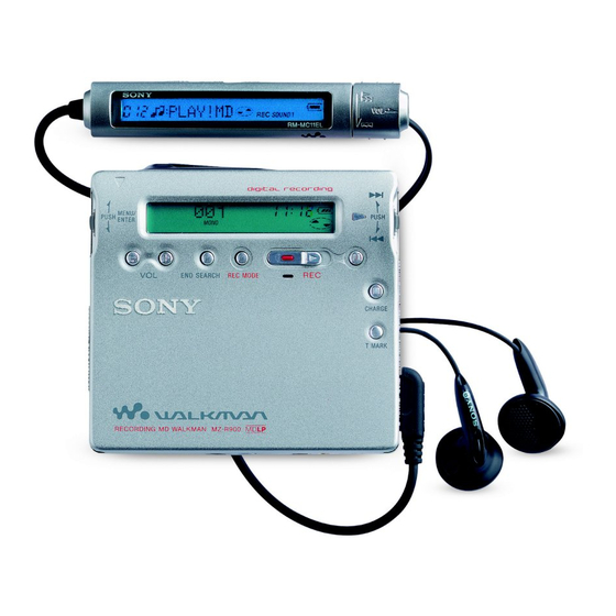
PORTABLE MINIDISC RECORDER
MZ-R900
US Model
Canadian Model
AEP Model
UK Model
Australian Model
Chinese Model
Tourist Model
Battery operation time
1)
Battery life
2)
When recording
(Unit: approx.hours)(EIAJ
Batteries
Stereo
NH-14WM
8
nickel metal
hydride
rechargeable
4)
battery
LR6 (SG)
7
Sony alkaline
5)
dry battery
NH-14WM
19
nickel metal
hydride
rechargeable
4)
battery
+ One LR6
(SG)
5)
1)
The battery life may be shorter due to
operating conditions and the temperature of
the location.
2)
When you record, use a fully charged
rechargeable battery. Recording time may
differ according to the alkaline batteries.
– Continued on next page –
E Model
NEW
MT-MZR900-171
LCX-4R
3)
)
LP2
LP4
10.5
13
10
14
26
30
Advertisement
Table of Contents

Related Manuals for Sony Walkman MZ-R900


Summary of Contents for Sony Walkman MZ-R900
- Page 1 ACIRC (Advanced Cross Interleave Reed headphones/earphones or a line cable. nickel metal Solomon Code) Power requirements hydride Sampling frequency Sony AC Power Adaptor connected at the DC rechargeable 44.1 kHz IN 3V jack: battery Sampling rate converter 120 V AC, 60 Hz (US model) + One LR6 Input: 32 kHz/44.1 kHz/48 kHz...
-
Page 2: Table Of Contents
SONY PARTS WHOSE PART NUMBERS APPEAR AS DE FONCTIONNEMENT. NE REMPLACER CES COM- SHOWN IN THIS MANUAL OR IN SUPPLEMENTS PUB- POSANTS QUE PAR DES PIÈCES SONY DONT LES NUMÉROS SONT DONNÉS DANS CE MANUEL OU LISHED BY SONY. DANS LES SUPPLÉMENTS PUBLIÉS PAR SONY. -
Page 3: Servicing Notes
MZ-R900 SECTION 1 SERVICING NOTES • In performing the repair with the power supplied to the set, NOTES ON HANDLING THE OPTICAL PICK-UP removing the MAIN board causes the set to be disabled. BLOCK OR BASE UNIT In such a case, fix a convex part of the open/close detect switch The laser diode in the optical pick-up block may suffer electro- (S806 on MAIN board) with a tape in advance. -
Page 4: General
MZ-R900 SECTION 2 This section is extracted from instruction manual. GENERAL Looking at controls The display window of the recorder See pages in ( ) for more details. The recorder A Alarm indication (53) J REC indication (17) Lights up while recording. When... -
Page 5: Disassembly
MZ-R900 SECTION 3 DISASSEMBLY • This set can be disassembled in the order shown below. 3-1. DISASSEMBLY FLOW 3-2. PANEL ASSY, 3-3. PANEL ASSY, 3-5. MAIN BOARD ASSY 3-6. “CASE ASSY, BATTERY”, BOTTOM UPPER SECTION “MAIN BOARD” 3-4. “LCD MODULE”, “PANEL ASSY, UPPER”... -
Page 6: Panel Assy, Upper Section
MZ-R900 3-3. PANEL ASSY, UPPER SECTION 1 flexible board (CN801) 3 two screws (1.4) 4 panel assy, upper section 3 two screws (1.4) 2 Push button (open). 3-4. “LCD MODULE”, “PANEL ASSY, UPPER” 1 four screws (1.7) 2 LCD module... -
Page 7: Main Board Assy
MZ-R900 3-5. MAIN BOARD ASSY 6 flexible board (CN501) 7 main board assy 1 Remove two solders of flexible board. 3 four screws (M1.4 toothed lock) 4 screw (1.4) 2 flexible board (CN502) 3-6. “CASE ASSY, BATTERY”, “MAIN BOARD” 2 case assy, battery... -
Page 8: Strip, Ornamental
MZ-R900 3-7. STRIP, ORNAMENTAL 1 Pull toward the direction A to disengage two bosses 5 Remove the “strip, ornamental” in the direction of arrow C . 2 Open toward the direction B Note: As the “strip, ornamental” to disengage two bosses... -
Page 9: Service Assy, Op (Lcx-4R)
MZ-R900 3-9. SERVICE ASSY, OP (LCX-4R) 2 gear (SA) 6 screw (M1.4) 1 washer (0.8-2.5) 7 spring, thrust 3 screw (M1.4) 9 Pull off “screw, lead” 4 spring (S), rack 5 screw 0 bearing (N) qa Opening the over write head toward the direction A , remove the “service assy, OP... -
Page 10: Holder Assy
MZ-R900 3-10. HOLDER ASSY 5 Remove the holder assy in the direction of arrow D . 2 Push the convex portion 1 Open the holder assy. toward the direction B and open the holder assy toward the direction A to erect uprightly. -
Page 11: Motor, Dc (Sled) (M602)
MZ-R900 3-12. MOTOR, DC (SLED) (M602) 1 Remove four solders of motor flexible board. 2 washer (0.8-2.5) 4 two screws (M1.4) 3 gear (SA) 5 motor, DC (sled) (M602) 3-13. “MOTOR, DC (SPINDLE) (M601)”, “MOTOR, DC (OVER WRITE HEAD UP/DOWN) (M603)”... -
Page 12: Test Mode
MZ-R900 SECTION 4 TEST MODE Outline Operation in Setting the Test Mode • This set provides the Overall adjustment mode that allows CD • When the test mode becomes active, first the display check mode and MO discs to be automatically adjusted when in the test mode. - Page 13 MZ-R900 Configuration of Test Mode [VOL +] key:100th place of item number [Major item switching] increase. [Test Mode $Display Check Mode%] [VOL --] key:100th place of item number [VOL +] Press the > decrease. [Manual Mode] Press the [VOL +]...
- Page 14 MZ-R900 5. The display changes a shown below each time the Self-Diagnosis Result Display Mode [JOG LEVER $L% ] [DISPLAY] (up) key or key on the remote This set uses the self-diagnostic function system in which if an commander is pressed.
- Page 15 MZ-R900 • Description of Error Indication Codes Problem Indication code Meaning of code Simple display Description No error No error No error Illegal access target Adrs Attempt to access an abnormal address address was specified Servo system error High temperature...
- Page 16 MZ-R900 Sound Skip Check Result Display Mode Key Check Mode This set can display the count of errors that occurred during the This set can check if the set and remote commander function nor- recording/playing for checking. mally. • Setting method of sound skip check result display •...
-
Page 17: Electrical Adjustments
2. Use the following tools and measuring instruments. • Test CD disc TDYS-1 Remote commander LCD display (Part No. : 4-963-646-01) • SONY MO disc available on the market • Digital voltmeter • Laser power meter LPM-8001 NV reset (after several seconds) (Part No. - Page 18 MZ-R900 7) Select the manual mode of the test mode, and set item number • Adjustment method of Vc PWM Duty (L) 871 (see page 13). (item number: 762) Remote commander LCD display Remote commander LCD display :Adjusted value : Adjusted value...
- Page 19 MZ-R900 2. When press the key to write the adjusted value, LCD dis- 7. Press the key, and set the laser CD read adjustment plays as follows and power supply manual adjustment has com- mode (item number 012). pleted. Remote commander LCD display Remote commander LCD display 8.
- Page 20 MZ-R900 Overall Adjustment Mode • Overall Adjustment Mode (Title Display) • Configuration of overall adjustment Remote commander LCD display Overall adjustment mode (Title display) : (Disc mark) At end of power supply adjustment: Outside lit Protect switch At end of electrical offset adj.: Inside lit Note: On the set having microcomputer version 1.000, the disc...
- Page 21 MZ-R900 • Adjustment Method of Overall CD and MO Adjustment • Overall CD and MO adjustment items Mode 1. Overall CD adjustment items 1. Setting the test mode (see page 12). Item No. Description [VOL --] 2. Press the key activates the overall adjust- ment mode.
- Page 22 MZ-R900 Resume Clear 7. Press the key. (0D58 is blinking) Perform the Resume clear when all adjustments completed. Remote commander LCD display • Resume Clear Setting Method 1. Select the manual mode of the test mode, and set item number 043 (see page 13).
- Page 23 MZ-R900 [VOL+] [VOL+] [VOL--] 20. Press the key once to change the blinking portion to 34. Adjust with the key (adjusted value up) or 0D60. key (adjusted value down) so that the adjusted value becomes Remote commander LCD display Remote commander LCD display...
- Page 24 MZ-R900 [VOL+] 8. Press the key. 23. Press the key once to change the blinking portion to (00 is blinking) 0D65. [VOL+] [VOL--] 9. Adjust with the key (adjusted value up) or Remote commander LCD display key (adjusted value down) so that the adjusted value becomes...
- Page 25 MZ-R900 [VOL+] [VOL--] [VOL+] 37. Adjust with the key (adjusted value up) or 51. Press the key to change the blinking portion to 0D72. key (adjusted value down) so that the adjusted value becomes Remote commander LCD display Remote commander LCD display :Adjusted value 52.
- Page 26 MZ-R900 [VOL+] [VOL--] [DISPLAY] 65. Adjust with the key (adjusted value up) or 79. Press the key on the remote commander for sev- key (adjusted value down) so that the adjusted value becomes eral seconds (about 3 seconds) to exit the patch data write mode (to return to the manual mode display in the test mode).
-
Page 27: Diagrams
MZ-R900 SECTION 6 DIAGRAMS 6-1. BLOCK DIAGRAM – SERVO Section – OVER WRITE HEAD DRIVE IC601 (1/2) SIGNAL PATH HR601 : PLAYBACK OVER WRITE OVER HEAD DRIVE OPTICAL PICK-UP BLOCK PRE DRIVER WRITE : REC (ANALOG IN) Q604, 605 (LCX-4R) -
Page 28: Block Diagram -Audio Section
MZ-R900 6-2. BLOCK DIAGRAM – AUDIO Section – OPTICAL RECEIVER B+ SWITCH VIF B+ Q302 DIN1 (Page 27) J301 LINE IN (OPT) (LINE IN JACK) MIC AMP IC303 J303 LIN2 OUT2 LIN1 (PLUG IN POWER) ADDT SDTO GAIN CONVERTER (Page 27) RIN2 &... -
Page 29: Block Diagram -Key Control/Display/ Power Supply Section
6-3. BLOCK DIAGRAM – KEY CONTROL/DISPLAY/POWER SUPPLY Section – RMC KEY (Page 28) VRMC HEADPHONE AMP (IC302), XWK3 MOTOR/COIL DRIVER (IC551) RMC KEY CLK SEL CLK SEL FFCLR FFCLR SLEEP SLEEP SYSTEM VLON (Page 27) CONTROL VLON XWK1 POWER CONTROL WK DET IC901 XWK2... - Page 30 MZ-R900 • Waveforms 1 IC501 8 (IY) (PLAYBACK mode) 6 IC501 ed (RF OUT) (PLAYBACK mode) qa IC801 rj (FE) (PLAYBACK mode) qh IC801 ih (FS4) 100 mV/DIV, 1 s/DIV 500 mV/DIV, 500 ns/DIV 10 mV/DIV, 500 ns/DIV 500 mV/DIV, 2 s/DIV Approx.
-
Page 31: Printed Wiring Boards
MZ-R900 6-4. PRINTED WIRING BOARDS Note on Schematic Diagram: • Semiconductor • All capacitors are in F unless otherwise noted. pF: Location 50 WV or less are not indicated except for electrolytics and tantalums. Ref. No. Location • All resistors are in... -
Page 32: Schematic Diagram
MZ-R900 6-5. SCHEMATIC DIAGRAM • • See page 33 for Waveforms. See page 43 for IC Block Diagrams... - Page 33 MZ-R900 • IC Block Diagrams IC501 SN761057DBT IC301 AK4562VNS-L ADIP-IN S-MON A+B+C+D TWpp 19 18 PK/BTM CLOCK CSLO CONTROL CCLK DIVIDER REXT VREF075 REGISTER Wpp LPF Aw+Dw S-MONITOR AUDIO I/F TON Peak VREF CONTROLLER TON Botm Malfa ADIP DGND AwBPF...
- Page 34 IC551 SC111257FCR2 IC601 XPC18A22FCR2 42 41 – VC2 VG VC VG OUTPUT SW OUTPUT SW CHARGE CHARGE – PUMP 2 PUMP 1 PRE DRIVER PRE DRIVER VC VG DC IN HI-BRIDGE CHARGE PGNDW PRE DRIVER PRE DRIVER MONITOR VREF VREF X2/X4 BATM BUFFER...
-
Page 35: Ic Pin Function Description
MZ-R900 6-6. IC PIN FUNCTION DESCRIPTION IC501 SN761057DBT (RF AMP, FOCUS/TRACKING ERROR AMP) Pin No. Pin Name Description Tracking error signal output to the system controller (IC801) REXT — Connect terminal to the external resistor for ADIP amp control WPPLPF —... - Page 36 MZ-R900 IC801 CXD2671-202GA (SYSTEM CONTROLLER, DIGITAL SIGNAL PROCESSOR, 16M BIT D-RAM) Pin No. Pin Name Description PAUSE KEY Set key input terminal (X key input) Control signal output to the microphone amp (IC303) “H”: HIGH, “L”: LOW, MIC SENSE normally: “H”...
- Page 37 MZ-R900 Pin No. Description Pin Name Focus error signal input from RF amp (IC501) AUX1 Support signal (I signal/temperature signal) input terminal (A/D input) Middle point voltage (+1.2V) input terminal ADIO Monitor output of A/D converter input signal Not used (open) ADRT A/D converter the upper limit voltage input (fixed at “H”...
- Page 38 MZ-R900 Pin No. Description Pin Name — DSPVDD2 Power supply terminal (for DSP block) (+1.5V) — DSPVSS1 Ground terminal (for DSP block) SPCU Spindle motor drive comparison signal input (U) from the motor driver (IC551) SPCV Spindle motor drive comparison signal input (V) from the motor driver (IC551)
- Page 39 MZ-R900 Pin No. Description Pin Name 156, 157 TEST1, TEST0 Input terminal for the main test (normally fixed at “L”) EVA/FLASH chip discrimination terminal “L”: FLASH chip, “H”: EVA chip Not used (open) SSB DATA Input/output of SSB serial data with RF amp (IC501)
- Page 40 MZ-R900 Pin No. Description Pin Name XPD ADA Power supply control signal output for the drive to A/D, D/A converter (IC301) XCS LCD Chip select signal output to the liquid crystal display element LCD STB Strobe signal output to the liquid crystal display element...
-
Page 41: Exploded Views
MZ-R900 SECTION 7 EXPLODED VIEWS NOTE: • -XX and -X mean standardized parts, so they • Items marked “*” are not stocked since they The components identified by mark 0 or dotted line with mark 0 are may have some difference from the original are seldom required for routine service. -
Page 42: Chassis Section
MZ-R900 7-2. CHASSIS SECTION MT-MZR900-171 not supplied Ref. No. Part No. Description Remark Ref. No. Part No. Description Remark 3-220-477-01 SHEET (MD), INSULATING * 59 A-3323-704-A MAIN BOARD, COMPLETE (US, CND) X-3379-320-5 CHASSIS ASSY, SET 3-220-471-01 SPRING (ARM), TENSION 4-218-233-07 SCREW (1.4), MI 3-335-797-91 SCREW (M1.4), TOOTHED LOCK... -
Page 43: Md Mechanism Deck Section (Mt-Mzr900-171)
MZ-R900 7-3. MD MECHANISM DECK SECTION (MT-MZR900-171) M603 not supplied M602 M601 The components identified by Les composants identifiés par une mark 0 or dotted line with marque 0 sont critiques pour la mark 0 are critical for safety. sécurité. -
Page 44: Electrical Parts List
MZ-R900 SECTION 8 MAIN ELECTRICAL PARTS LIST NOTE: • Due to standardization, replacements in the • Items marked “*” are not stocked since they The components identified by 0 or dotted line with mark mark parts list may be different from the parts speci- are seldom required for routine service. - Page 45 MZ-R900 MAIN Ref. No. Part No. Description Remark Ref. No. Part No. Description Remark C519 1-164-940-11 CERAMIC CHIP 0.0033uF 10% C812 1-164-943-11 CERAMIC CHIP 0.01uF C813 1-125-891-11 CERAMIC CHIP 0.47uF C521 1-125-777-11 CERAMIC CHIP 0.1uF C814 1-164-935-11 CERAMIC CHIP 470PF...
- Page 46 MZ-R900 MAIN Ref. No. Part No. Description Remark Ref. No. Part No. Description Remark D602 8-719-081-33 DIODE MA2YD1500LS0 L603 1-469-535-21 INDUCTOR 10uH L801 1-469-535-21 INDUCTOR 10uH D603 8-719-081-34 DIODE RB160M-30TR L802 1-469-535-21 INDUCTOR 10uH D605 8-719-081-34 DIODE RB160M-30TR L901 1-419-952-21 INDUCTOR...
- Page 47 MZ-R900 MAIN Ref. No. Part No. Description Remark Ref. No. Part No. Description Remark R606 1-218-949-11 RES-CHIP 1/16W R909 1-218-965-11 RES-CHIP 1/16W R607 1-218-945-11 RES-CHIP 1/16W R910 1-218-965-11 RES-CHIP 1/16W R608 1-218-983-11 RES-CHIP 330K 1/16W R911 1-218-949-11 RES-CHIP 1/16W R609...
- Page 48 MZ-R900 Ref. No. Part No. Description Remark Ref. No. Part No. Description Remark 1-476-395-11 REMOTE CONTROL UNIT (RM-MC11EL) 1-476-275-11 ADAPTOR, AC (AC-MZR55) (AEP, E13, FR, EE) 1-476-277-11 ADAPTOR, AC (AC-MZR55) (UK, HK) 1-476-278-11 ADAPTOR, AC (AC-MZR55) (AUS) 1-476-279-11 ADAPTOR, AC (AC-MZR55) (US, CND)
- Page 49 MZ-R900 MEMO...
- Page 50 MZ-R900 REVISION HISTORY Clicking the version allows you to jump to the revised page. Also, clicking the version at the upper right on the revised page allows you to jump to the next revised page. Ver. Date Description of Revision 2001.03...