Table of Contents
Advertisement
Quick Links
Advertisement
Table of Contents

Related Manuals for Asus P9X79 WS


Summary of Contents for Asus P9X79 WS
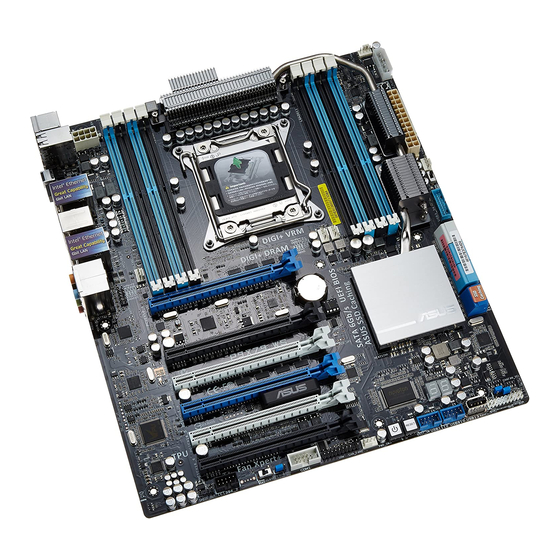
- Page 1 P9X79 WS...
- Page 2 Product warranty or service will not be extended if: (1) the product is repaired, modified or altered, unless such repair, modification of alteration is authorized in writing by ASUS; or (2) the serial number of the product is defaced or missing.
-
Page 3: Table Of Contents
Contents Contents ...................... iii Notices ......................vii Safety information ..................ix About this guide ..................x P9X79 WS specifications summary ............xii Chapter 1: Product introduction Welcome! ..................1-1 Package contents ................. 1-1 Special features ................1-2 1.3.1 Product highlights ............1-2 1.3.2... -
Page 4: Contents
3.5.8 APM ................3-39 Monitor menu ................3-40 Boot menu .................. 3-43 Tools menu ................. 3-44 3.8.1 ASUS EZ Flash 2 Utility ..........3-45 3.8.2 ASUS DRAM SPD Information ........3-45 3.8.3 ASUS O.C. Profile ............3-46 3.8.4 ASUS Drive Xpert ............3-47 Exit menu .................. - Page 5 Contents 3.10.1 ASUS Update utility ............3-49 3.10.2 ASUS EZ Flash 2 utility ..........3-52 3.10.3 ASUS CrashFree BIOS 3 utility ........3-53 3.10.4 ASUS BIOS Updater ............. 3-54 Chapter 4: Software support Installing an operating system ........... 4-1 Support DVD information ............4-1 4.2.1...
- Page 6 Chapter 5: Multiple GPU technology support CrossFireX™ technology ............ 5-1 ® 5.1.1 Requirements ..............5-1 5.1.2 Before you begin ............. 5-1 5.1.3 Installing CrossFireX graphics cards ......5-2 5.1.4 Installing the device drivers ..........5-3 5.1.5 Enabling the ATI CrossFireX™ technology ....5-3 ®...
-
Page 7: Notices
Notices Federal Communications Commission Statement This device complies with Part 15 of the FCC Rules. Operation is subject to the following two conditions: • This device may not cause harmful interference, and • This device must accept any interference received including interference that may cause undesired operation. - Page 8 REACH.htm. ASUS Recycling/Takeback Services ASUS recycling and takeback programs come from our commitment to the highest standards for protecting our environment. We believe in providing solutions for you to be able to responsibly recycle our products, batteries, other components as well as the packaging materials.
-
Page 9: Safety Information
Safety information Electrical safety • To prevent electrical shock hazard, disconnect the power cable from the electrical outlet before relocating the system. • When adding or removing devices to or from the system, ensure that the power cables for the devices are unplugged before the signal cables are connected. If possible, disconnect all power cables from the existing system before you add a device. -
Page 10: About This Guide
Refer to the following sources for additional information and for product and software updates. ASUS websites The ASUS website provides updated information on ASUS hardware and software products. Refer to the ASUS contact information. Optional documentation Your product package may include optional documentation, such as warranty flyers, that may have been added by your dealer. -
Page 11: Conventions Used In This Guide
Conventions used in this guide To ensure that you perform certain tasks properly, take note of the following symbols used throughout this manual. DANGER/WARNING: Information to prevent injury to yourself when trying to complete a task. CAUTION: Information to prevent damage to the components when trying to complete a task. -
Page 12: P9X79 Ws Specifications Summary
Xeon series processor for the LGA 2011 Socket ® ® * Supports Intel Turbo Boost Technology 2.0 ® ** Refer to www.asus.com for CPU support list Chipset Intel X79 Express Chipset ® Memory 8 x DIMM, Max. 64GB, DDR3 2400(O.C.)/2133(O. - Page 13 - TPU Switch ASUS EPU - EPU Utility - EPU Switch ASUS Exclusive Features - ASUS UEFI BIOS EZ Mode featuring friendly graphics user interface - ASUS SSD Caching - USB 3.0 Boost - Front Panel USB 3.0 Support - MemOK!
- Page 14 ASUS WS 3-color LED BIOS Features 64 Mb Flash ROM, UEFI BIOS, PnP, DMI2.0, WfM2.0, SM BIOS 2.6, ACPI 2.0a, Multi-language BIOS, ASUS EZ Flash 2, ASUS CrashFree BIOS 3 Back Panel I/O Ports 2 x USB 3.0/2.0 ports (blue) 8 x USB 2.0/1.1 ports (white port can be switched to USB...
- Page 15 Accessories 4 x Serial ATA 6Gb/s cables 4 x Serial ATA 3Gb/s cables 1 x ASUS 4-Way SLI bridge connector 1 x ASUS 3-Way SLI bridge connector 1 x ASUS SLI bridge connector 2 in 1 Q-connector I/O shield User’s Manual...
-
Page 17: Chapter 1: Product Introduction
This chapter describes the motherboard features and the new technologies it supports. Chapter 1: Product introduction... - Page 18 Chapter summary Welcome! ..................1-1 Package contents ................. 1-1 Special features ................1-2 ASUS P9X79 WS...
-
Page 19: Welcome
Welcome! Thank you for buying an ASUS P9X79 WS motherboard! The motherboard delivers a host of new features and latest technologies, making it another standout in the long line of ASUS quality motherboards! Before you start installing the motherboard, and hardware devices on it, check the items in your package with the list below. -
Page 20: Special Features
* This motherboard is ready to support PCIe 3.0 SPEC. Functions will be available when using PCIe 3.0-compliant devices. Please refer to www.asus. com for updated details. Quad-Channel DDR3 2400(O.C.)/2133(O.C.)/1866/1600/1333/1066 MHz... -
Page 21: Asus Workstation Exclusive Features
ASUS facilitates strategic USB 3.0 accessibility for both the front and rear panel – 4USB 3.0 ports in total. Experience the latest plug & play connectivity at speeds up to 10 times faster than USB 2.0. The P9X79 WS affords greater convenience to high speed connectivity. -
Page 22: Asus Features
Quick Gate is a vertical USB connector on the motherboard, allowing you to install USB devices directly with no messy cables. This stops important data storage devices from breaking off unexpectedly. P9X79 WS with this unique design provides a convenient and safe way to install data and applications on your PC. -
Page 23: Asus Ssd Caching
This also reduces fan noise and extends component longevity. ASUS SSD Caching SSD caching from ASUS is easier than ever. At 3X faster, this feature boosts system performance by using an installed SSD with no capacity limitations as a cache for frequently accessed data. Harness a combination of SSD-like performance and response and hard drive capacity with just one click, no rebooting needed and instant activation for complete ease of use. -
Page 24: Usb Bios Flashback
ASUS Fan Xpert intelligently allows users to adjust both the CPU and chassis fan speed according to different ambient temperature, which is caused by different climate conditions in different geographic regions and system loading. - Page 25 ASUS EZ-Flash 2 ASUS EZ Flash 2 is a user-friendly utility that allows you to update the BIOS without using a bootable floppy disk or an OS-based utility. ASUS P9X79 WS...
-
Page 26: Other Special Features
The motherboard is European Union’s Energy-related Products (ErP) ready, and ErP requires products to meet certain energy efficiency requirement in regards to energy consumptions. This is in line with ASUS vision of creating environment- friendly and energy-efficient products through product design and innovation to reduce carbon footprint of the product and thus mitigate environmental impacts. -
Page 27: Chapter 2: Hardware Information
This chapter lists the hardware setup procedures that you have to perform when installing system components. It includes description of the jumpers and Chapter 2: Hardware connectors on the motherboard. information... - Page 28 Chapter summary Before you proceed ..............2-1 Motherboard overview ..............2-2 Building your computer system ..........2-30 Starting up for the first time ............2-46 Turning off the computer ............2-47 ASUS P9X79 WS...
-
Page 29: Before You Proceed
Before you install or remove any component, ensure that the ATX power supply is switched off or the power cord is detached from the power supply. Failure to do so may cause severe damage to the motherboard, peripherals, or components. ASUS P9X79 WS... -
Page 30: Motherboard Overview
Motherboard overview 2.2.1 Motherboard layout Refer to 2.2.9 Internal Connectors for more information about rear panel connectors and internal connectors. Chapter 2: Hardware information... -
Page 31: Layout Contents
2-10 IEEE 1394a port connector (10-1 pin IE1394_2) IEEE 1394a port connector (10-1 pin IE1394_2) 2-28 Digital audio connector (4-1 pin SPDIF_OUT) Digital audio connector (4-1 pin SPDIF_OUT) 2-28 Front panel audio connector (10-1 pin AAFP) 2-30 ASUS P9X79 WS... -
Page 32: Central Processing Unit (Cpu)
ASUS will shoulder the cost of repair only if the damage is shipment/transit-related. • Keep the cap after installing the motherboard. ASUS will process Return Merchandise Authorization (RMA) requests only if the motherboard comes with the cap on the LGA2011 socket. -
Page 33: System Memory
The motherboard comes with four Double Data Rate 3 (DDR3) Dual Inline Memory Modules (DIMM) slots. A DDR3 module is notched differently from a DDR or DDR2 module. DO NOT install a DDR or DDR2 memory module to the DDR3 slot. ® ® Recommended memory configurations ASUS P9X79 WS... -
Page 34: Memory Configurations
CPU. • The max. 64GB memory capacity can be supported with DIMMs of 8GB (or above). ASUS will update QVL once the DIMMs are available on the market. • Always install DIMMs with the same CAS latency. For optimum compatibility, we recommend that you obtain memory modules from the same vendor. -
Page 35: Expansion Slots
PCIe 2.0 x16_1 slot (single at x16 or dual at x8/x8 mode) PCIe 2.0 x16_2 slot (x8 mode) PCIe 2.0 x16_3 slot (x4 mode) PCIe 2.0 x16_4 slot (single at x16 or dual at x8/x8 mode) PCIe 2.0 x16_5 slot (x4 mode) PCIe 2.0 x16_6 slot (x8 mode) ASUS P9X79 WS... -
Page 36: Standard Interrupt Assignments
Standard Interrupt assignments Priority Standard function System Timer Keyboard Controller Programmable Interrupt Communications Port (COM1) IRQ Holder for PCI Steering Reserved Reserved System CMOS/Real Time Clock IRQ Holder for PCI Steering IRQ Holder for PCI Steering IRQ Holder for PCI Steering Reserved Numeric Data Processor Primary IDE Channel... -
Page 37: Onboard Switches
The illustration below shows the location of the onboard power-on switch. ® Reset switch Press the reset switch to reboot the system. ® ASUS P9X79 WS... - Page 38 EPU switch Turning this switch to Enable will automatically detect the current PC loadings and intelligently moderate the power consumption. For ensuring system performance, turn the switch setting to Enable when the system is powered off. ® TPU switch Turning this switch to Enable will automatically optimize the system for fast, yet stable clock speeds.
- Page 39 DIAG_DRAM lights continuously. Replace the DIMMs with ones recommended in the Memory QVL (Qualified Vendors Lists) in this user manual or on the ASUS website at www.asus.com. • If you turn off the computer and replace DIMMs during the tuning process, the system continues memory tuning after turning on the computer.
-
Page 40: Onboard Leds
2.2.7 Onboard LEDs Standby Power LEDs The motherboard comes with a standby power LED that lights up to indicate that the system is ON, in sleep mode, or in soft-off mode. This is a reminder that you should shut down the system and unplug the power cable before removing or plugging in any motherboard component. - Page 41 EPU LED The EPU LED lights when the EPU switch is turned to Enable. ® TPU LED The TPU LED lights when the TPU switch is turned to Enable. ® ASUS P9X79 WS 2-13...
- Page 42 WS 3-color LED The lighting color of the ASUS logo on the LED signifies Ai Tweaker settings. Instant O.C. status checking LED Activity Status Description Blue Normal Ai Tweaker Enabled/ Overclocking Green EPU Enabled/ Power saving mode P9X79 WS Lights up according to ®...
-
Page 43: Q-Code Table
15 – 18 Pre-memory System Agent initialization is started 19 – 1C Pre-memory PCH initialization is started 1D – 2A Pre-memory initialization codes 2B – 2F Memory initialization Reserved for ASL (see ASL Status Codes section below) ASUS P9X79 WS 2-15... - Page 44 Q-Code table (continued) Code Description Memory Installed 32 – 36 CPU post-memory initialization 37 – 3A Post-Memory System Agent initialization is started 3B – 3E Post-Memory PCH initialization is started 3F – 4E Post memory initialization codes DXE IPL is started Memory initialization error.
- Page 45 DXE initialization codes Boot Device Selection (BDS) phase is started Driver connecting is started PCI Bus initialization is started PCI Bus Hot Plug Controller Initialization PCI Bus Enumeration PCI Bus Request Resources PCI Bus Assign Resources ASUS P9X79 WS 2-17...
- Page 46 Q-Code table (continued) Code Description Console Output devices connect Console input devices connect Super IO Initialization USB initialization is started USB Reset USB Detect USB Enable 9E-9F Reserved for future AMI codes IDE initialization is started IDE Reset IDE Detect IDE Enable SCSI initialization is started SCSI Reset...
- Page 47 No Console Output Devices are found No Console Input Devices are found Invalid password Error loading Boot Option (LoadImage returned error) Boot Option is failed (StartImage returned error) Flash update is failed Reset protocol is not available ASUS P9X79 WS 2-19...
- Page 48 ACPI/ASL Checkpoints Code Description 0x01 System is entering S1 sleep state 0x02 System is entering S2 sleep state 0x03 System is entering S3 sleep state 0x04 System is entering S4 sleep state 0x05 System is entering S5 sleep state 0x10 System is waking up from the S1 sleep state 0x20 System is waking up from the S2 sleep state...
-
Page 49: Jumper
• Due to the chipset behavior, AC power off is required to enable C.P.R. function. You must turn off and on the power supply or unplug and plug the power cord before rebooting the system. ASUS P9X79 WS 2-21... - Page 50 Chassis Fan control setting (3-pin CHAFAN_SEL) These jumpers allow you to switch for fan pin selection. The CHAFAN_SEL jumper is for the front fans and rear fans control. Set to pins 1–2 when using 3-pin fans or pins 2–3 when using 4-pin fans. ®...
-
Page 51: Internal Connectors
XP SP3 or later versions. ® • You must load IRST Driver during OS installation for the system to detect the Optical Disk Drive (the ODD should be connected to the SATA_3G port), or else the ODD will not run. ASUS P9X79 WS 2-23... - Page 52 Intel X79 Serial ATA 3.0 Gb/s connectors ® (7-pin SATA3G_3–6 [blue]) These connectors connect to Serial ATA 3.0 Gb/s hard disk drives and optical disc drives via Serial ATA 3.0 Gb/s signal cables. If you installed Serial ATA hard disk drives, you can create a RAID 0, 1, 5, and 10 configuration with the Intel Rapid Storage Technology through the ®...
- Page 53 These connectors connect to Serial ATA 6.0 Gb/s hard disk drives via Serial ATA 6.0 Gb/s signal cables. ® • For high performance of ASUS SSD Caching, please connect one HDD and one SSD to Marvell SATA6G_E1/E2 connectors. ® •...
- Page 54 3.0 front panel cable is available from your system chassis, with this USB 3.0 connector, you can have a front panel USB 3.0 solution. ® You can connect the ASUS front panel USB 3.0 box to this connector to obtain the front panel USB 3.0 solution. 2-26...
- Page 55 Never connect a 1394 cable to the USB connectors. Doing so will damage the motherboard! You can connect the front panel USB cable to the ASUS Q-Connector (USB, blue) first, and then install the Q-Connector (USB) to the USB connector onboard if your chassis supports front panel USB ports.
- Page 56 IEEE 1394a port connector (10-1 pin IE1394_2) This connector is for an IEEE 1394a port. Connect the IEEE 1394a module cable to this connector, then install the module to a slot opening at the back of the system chassis. ® Never connect a USB cable to the IEEE 1394a connector.
- Page 57 The CPU_FAN connector supports the CPU fan of maximum 2A (24 W) fan power. • If you install two VGA cards, we recommend that you plug the rear chassis fan cable to the motherboard connector labeled CHA_FAN1, CHA_FAN2, CHA_FAN3 for better thermal environment. ASUS P9X79 WS 2-29...
- Page 58 Front panel audio connector (10-1 pin AAFP) This connector is for a chassis-mounted front panel audio I/O module that supports either HD Audio or legacy AC`97 audio standard. Connect one end of the front panel audio I/O module cable to this connector. ®...
- Page 59 This connector supports a Trusted Platform Module (TPM) system, which can securely store keys, digital certificates, passwords, and data. A TPM system also helps enhance network security, protects digital identities, and ensures platform integrity. This connector can also serve for G.P. Diagnosis card installation. ® ASUS P9X79 WS 2-31...
- Page 60 • If you are uncertain about the minimum power supply requirement for your system, refer to the Recommended Power Supply Wattage Calculator at http://support.asus.com/PowerSupplyCalculator/PSCalculator. aspx?SLanguage=en-us for details. • If you want to use two or more high-end PCI Express x16 cards, use a PSU with 1000W power or above to ensure the system stability.
- Page 61 14. EZ Plug connector (4-pin EZ_PLUG) This 4-pin connector is for HDD power supply plug. When using 3 or more graphic cards, more power may be needed, Use this connector to enhance power by 12V. ASUS P9X79 WS 2-33...
-
Page 62: System Panel Connector
15. System panel connector (20-8 pin PANEL) This connector supports several chassis-mounted functions. ® • System power LED (2-pin PLED) This 2-pin connector is for the system power LED. Connect the chassis power LED cable to this connector. The system power LED lights up when you turn on the system power, and blinks when the system is in sleep mode. -
Page 63: Building Your Computer System
Intel LGA 2011 CPU Intel LGA 2011 compatible CPU Fan DIMM SATA hard disk drive SATA optical disc drive (optional) Graphics card The tools and components in the table above are not included in the motherboard package. ASUS P9X79 WS 2-35... -
Page 64: Cpu Installation
2.3.2 CPU installation Please note the order in opening/ closing the double latch. Follow the instructions printed on the metal sealing hatch or the illustrations shown below in this manual. The plastic cap will pop up automatically once the CPU is in place and the hatch properly sealed down. - Page 65 Triangle mark ASUS P9X79 WS 2-37...
-
Page 66: Cpu Heatsink And Fan Assembly Installation
2.3.3 CPU heatsink and fan assembly installation Apply the Thermal Interface Material to the CPU heatsink and CPU before you install the heatsink and fan if necessary. To install the CPU heatsink and fan assembly 2-38 Chapter 2: Hardware information... -
Page 67: Dimm Installation
2.3.4 DIMM installation To remove a DIMM ASUS P9X79 WS 2-39... -
Page 68: Motherboard Installation
2.3.5 Motherboard installation The diagrams in this section are for reference only. The motherboard layout may vary with models, but the installation steps remain the same. 2-40 Chapter 2: Hardware information... - Page 69 DO NOT overtighten the screws! Doing so can damage the motherboard. ASUS P9X79 WS 2-41...
-
Page 70: Atx Power Connection
2.3.6 ATX Power connection 2-42 Chapter 2: Hardware information... -
Page 71: Sata Device Connection
2.3.7 SATA device connection ASUS P9X79 WS 2-43... -
Page 72: Front I/O Connector
2.3.8 Front I/O Connector To install ASUS Q-Connector To install USB Connector To install front panel audio connector AAFP The actual location may vary with motherboards. 2-44 Chapter 2: Hardware information... -
Page 73: Rear Panel Connection
11. USB 3.0 ports 1 and 2 6. USB 2.0 ports 1, 2, 3, and 4 12. Audio I/O ports** *and **: Refer to the tables on the next page for LAN port and audio port definitions. ASUS P9X79 WS 2-45... -
Page 74: Audio I/O Connections
• Due to USB 3.0 controller limitation, USB 3.0 devices can only be used under Windows OS environment and after the USB 3.0 driver installation. ® • USB 3.0 devices can only be used as data storage only. • We strongly recommend that you connect USB 3.0 devices to USB 3.0 ports for faster and better performance for your USB 3.0 devices. - Page 75 Connect to Stereo Speakers Connect to 2.1 channel Speakers Connect to 4.1 channel Speakers ASUS P9X79 WS 2-47...
- Page 76 Connect to 5.1 channel Speakers Connect to 7.1 channel Speakers 2-48 Chapter 2: Hardware information...
-
Page 77: Usb Bios Flashback
2.3.11 USB BIOS Flashback Download the BIOS Flashback program file from the ASUS service website (www.asus.com). Save the program file to a USB portable disk. On the rear I/O port, plug the USB disk to USB port 1 with the WHITE interior. -
Page 78: Starting Up For The First Time
Starting up for the first time After making all the connections, replace the system case cover. Be sure that all switches are off. Connect the power cord to the power connector at the back of the system chassis. Connect the power cord to a power outlet that is equipped with a surge protector. -
Page 79: Turning Off The Computer
BIOS setting. Pressing the power switch for more than four seconds lets the system enter the soft-off mode regardless of the BIOS setting. Refer to section 3.7 Boot Menu for details. ASUS P9X79 WS 2-51... - Page 80 2-52 Chapter 2: Hardware information...
-
Page 81: Chapter 3: Bios Setup
BIOS setup Knowing BIOS The new ASUS UEFI BIOS is an Extensible Firmware Interface that complies with UEFI architecture, offering a user-friendly interface that goes beyond traditional keyboard-only BIOS controls to enable more flexible and convenient mouse input. Users can easily navigate the new UEFI BIOS with the same smoothness as their operating system. -
Page 82: Ez Mode
Exits the BIOS setup program without saving CPU/5V/3.3V/12V voltage output, the changes, saves the changes and resets CPU/CPU_OPT/Chassis fan speed the system, or enters the Advanced Mode P9X79 WS Quick switch to frequently Loads optimized default Power Saving mode used menus. -
Page 83: Advanced Mode
The Advanced Mode provides advanced options for experienced end-users to configure the BIOS settings. The figure below shows an example of the Advanced Mode. Refer to the following sections for the detailed configurations. To access the EZ Mode, click Exit, then select ASUS EZ Mode. Menu items Menu bar... -
Page 84: Menu Items
Menu items The highlighted item on the menu bar displays the specific items for that menu. For example, selecting Main shows the Main menu items. The other items (Ai Tweaker, Advanced, Monitor, Boot, Tool, and Exit) on the menu bar have their respective menu items. -
Page 85: Main Menu
RAM to clear the BIOS password. See section 2.2.8 Jumpers for information on how to erase the RTC RAM. • The Administrator or User Password items on top of the screen show the default Not Installed. After you set a password, these items show Installed. ASUS P9X79 WS... -
Page 86: Administrator Password
Administrator Password If you have set an administrator password, we recommend that you enter the administrator password for accessing the system. Otherwise, you might be able to see or change only selected fields in the BIOS setup program. To set an administrator password: Select the Administrator Password item and press <Enter>. -
Page 87: Ai Tweaker Menu
Be cautious when changing the settings of the Ai Tweaker menu items. Incorrect field values can cause the system to malfunction. The configuration options for this section vary depending on the CPU and DIMM model you installed on the motherboard. Scroll down to display the following items: ASUS P9X79 WS... - Page 88 Scroll down to display the following items: Ai Overclock Tuner [Auto] Allows you to select the CPU overclocking options to achieve the desired CPU internal frequency. Select any of these preset overclocking configuration options: [Auto] Loads the optimal settings for the system. [Manual] Allows you to individually set overclocking parameters.
- Page 89 Configuration options: [Auto] [Light Power Saving Mode] [Medium Power Saving Mode] [Max Power Saving Mode] OC Tuner OC Tuner automatically overclocks the frequency and voltage of CPU and DRAM for enhancing the system performance. Configuration options: [OK] [Cancel] ASUS P9X79 WS...
-
Page 90: Dram Timing Control
3.4.1 DRAM Timing Control The sub-items in this menu allow you to set the DRAM timing control features. Use the <+> and <-> keys to adjust the value. To restore the default setting, type [auto] using the keyboard and press the <Enter> key. Changing the values in this menu may cause the system to become unstable! If this happens, revert to the default settings. - Page 91 Scroll down to display the following items: Scroll down to display the following items: ASUS P9X79 WS 3-11...
- Page 92 Scroll down to display the following items: Primary Timings DRAM CAS# Latency [Auto] Use the <+> and <-> keys to adjust the value. The values range from 3 to 15 with 1 interval. The values range from 3 to 15 with 1 interval. DRAM RAS# to CAS# Delay [Auto] Use the <+>...
- Page 93 Use the <+> and <-> keys to adjust the value. The values range from 0 to 15 with 1 interval. tCCD [Auto] Use the <+> and <-> keys to adjust the value. The values range from 0 to 7 with 1 interval. ASUS P9X79 WS 3-13...
- Page 94 Latency Timings DRAM RTL (CHA D0 R0) [Auto] Configuration options: [Auto] [Advance 14 Clock] [Advance 12 Clock] [Advance 10 Clock] [Advance 8 Clock] [Advance 6 Clock] [Advance 4 Clock] [Advance 2 Clock] [Normal] [Delay 2 Clock] [Delay 4 Clock] [Delay 6 Clock] [Delay 8 Clock] [Delay 10 Clock] [Delay 12 Clock] [Delay 14 Clock] DRAM IOL (CHA D0 R0) [Auto] Configuration options: [Auto] [Advance 14 Clock] [Advance 13 Clock] [Advance 12 Clock]...
- Page 95 Configuration options: [Auto] [Advance 14 Clock] [Advance 12 Clock] [Advance 10 Clock] [Advance 8 Clock] [Advance 6 Clock] [Advance 4 Clock] [Advance 2 Clock] [Normal] [Delay 2 Clock] [Delay 4 Clock] [Delay 6 Clock] [Delay 8 Clock] [Delay 10 Clock] [Delay 12 Clock] [Delay 14 Clock] ASUS P9X79 WS 3-15...
- Page 96 DRAM IOL (CHB D1 R0) [Auto] Configuration options: [Auto] [Advance 14 Clock] [Advance 13 Clock] [Advance 12 Clock] [Advance 11 Clock] [Advance 10 Clock] [Advance 9 Clock] [Advance 8 Clock] [Advance 7 Clock] [Advance 6 Clock] [Advance 5 Clock] [Advance 4 Clock] [Advance 3 Clock] [Advance 2 Clock] [Advance 1 Clock] [Normal] [Delay 1 Clock] [Delay 2 Clock] [Delay 3 Clock] [Delay 4 Clock] [Delay 5 Clock] [Delay 6 Clock] [Delay 7 Clock] [Delay 8 Clock] [Delay 9 Clock] [Delay 10 Clock] [Delay 11 Clock] [Delay 12 Clock] [Delay 13 Clock] [Delay 14 Clock]...
- Page 97 Configuration options: [Auto] [Advance 14 Clock] [Advance 12 Clock] [Advance 10 Clock] [Advance 8 Clock] [Advance 6 Clock] [Advance 4 Clock] [Advance 2 Clock] [Normal] [Delay 2 Clock] [Delay 4 Clock] [Delay 6 Clock] [Delay 8 Clock] [Delay 10 Clock] [Delay 12 Clock] [Delay 14 Clock] ASUS P9X79 WS 3-17...
- Page 98 DRAM IOL (CHD D0 R1) [Auto] Configuration options: [Auto] [Advance 14 Clock] [Advance 13 Clock] [Advance 12 Clock] [Advance 11 Clock] [Advance 10 Clock] [Advance 9 Clock] [Advance 8 Clock] [Advance 7 Clock] [Advance 6 Clock] [Advance 5 Clock] [Advance 4 Clock] [Advance 3 Clock] [Advance 2 Clock] [Advance 1 Clock] [Normal] [Delay 1 Clock] [Delay 2 Clock] [Delay 3 Clock] [Delay 4 Clock] [Delay 5 Clock] [Delay 6 Clock] [Delay 7 Clock] [Delay 8 Clock] [Delay 9 Clock] [Delay 10 Clock] [Delay 11 Clock] [Delay 12 Clock] [Delay 13 Clock] [Delay 14 Clock]...
- Page 99 Use the <+> and <-> keys to adjust the value. The values range from 0 to 31 with 1 interval. MCH Duty Sense (CHD) [Auto] Use the <+> and <-> keys to adjust the value. The values range from 0 to 31 with 1 interval. MCH Recheck [Auto] Configuration options: [Auto] [Disabled] [Enabled] ASUS P9X79 WS 3-19...
-
Page 100: Digi+ Power Control
DRAM-CD Current Capability 100% F2: Previous Values F3: Shortcut DRAM-CD Voltage Frequency Auto F5: Optimized Defaults F6: ASUS Ratio Boost DRAM-CD Power Phase Control Optimized F10: Save ESC: Exit F12: Print Screen Version 2.10.1208. Copyright (C) 2011 American Megatrends, Inc. - Page 101 Use the <+> and <-> keys to adjust the value. The values range from 300k~500kHz with a 10k Hz interval. Do not remove the thermal module when switching to Manual mode. The thermal conditions should be monitored. ASUS P9X79 WS 3-21...
- Page 102 O.C range or a lower DRAM frequency for better system stability. Configuration options: [Auto] [Manual] DRAM-AB Power Phase control [Auto] [Auto] Proceeds preset phase tuning profile. [Optimized] Allows you to set ASUS optimized phase tuning profile. [Extreme] Allows you to set the Full phase mode. 3-22 Chapter 3: BIOS setup...
- Page 103 O.C range or a lower DRAM frequency for better system stability. Configuration options: [Auto] [manual] DRAM-CD Power Phase control [Auto] [Auto] Proceeds preset phase tuning profile. [Optimized] Allows you to set ASUS optimized phase tuning profile. [Extreme] Allows you to set the Full phase mode. ASUS P9X79 WS 3-23...
-
Page 104: Cpu Performance Settings
3.4.2 CPU Performance Settings The items in this menu is setting for CPU Ratio/Features. is setting for CPU Ratio/Features. UEFI BIOS Utility - Advanced Mode Exit Ai Tweaker Main Advanced Monitor Boot Tool CPU Ratio Auto Allows users to manually adjust the maximum non-turbo CPU ratio. - Page 105 Power Limit 1. Intel recommends that the platform must be capable of supporting over Power Limit 2 for up to 10 msec. ASUS board can support over Power Limit 2 for a long duration. Use the <+> and <-> keys to adjust the value.
- Page 106 Offset Mode Sign [+] This item appears only when you set the CPU VCORE Voltage item to [Offset Mode]. To offset the voltage by a positive value. [–] To offset the voltage by a negative value. CPU VCORE Offset Voltage [Auto] This item appears only when you set the CPU VCORE Voltage item to [Offset Mode] and allows you to set the VCORE offset voltage.
- Page 107 0.3950x to 0.6300x with a 0.005x interval. DRAM DATA REF Voltage on CHB [Auto] Allows you to set the DRAM DATA REF Voltage on Channel B. The values range from 0.3950x to 0.6300x with a 0.005x interval. ASUS P9X79 WS 3-27...
- Page 108 DRAM CTRL REF Voltage on CHC [Auto] Allows you to set the DRAM CTRL REF Voltage on Channel C. The values range from 0.3950x to 0.6300x with a 0.005x interval. DRAM DATA REF Voltage on CHC [Auto] Allows you to set the DRAM DATA REF Voltage on Channel C. The values range from 0.3950x to 0.6300x with a 0.005x interval.
-
Page 109: Advanced Menu
↑↓: Select Item Enter: Select +/-: Change Opt. F1: General Help F2: Previous Values F3: Shortcut F5: Optimized Defaults F6: ASUS Ratio Boost F10: Save ESC: Exit F12: Print Screen Version 2.10.1208. Copyright (C) 2011 American Megatrends, Inc. ASUS P9X79 WS 3-29... -
Page 110: Cpu Configuration
Limit CPUID Maximum Disabled F2: Previous Values F3: Shortcut Execute Disable Bit Enabled F5: Optimized Defaults F6: ASUS Ratio Boost Intel Virtualization Technology Enabled F10: Save ESC: Exit F12: Print Screen > CPU Power Management Configuration Version 2.10.1208. Copyright (C) 2011 American Megatrends, Inc. -
Page 111: Cpu Power Management Configuration
(The valid value ranges may vary according to your CPU model.) The valid value ranges may vary according to your CPU model.) [Values 12~20] Presets Enhanced Intel SpeedStep Technology and Turbo Mode to [Disabled] but can be adjusted. [Values 21~22] Disallows configuration for Turbo Mode. ASUS P9X79 WS 3-31... -
Page 112: System Agent Configuration
Enhanced Intel SpeedStep Technology [Enabled] Enhanced Intel SpeedStep Technology (EIST) allows the system operation to dynamically ® adjust processor voltage and cores frequency, which can result in decreased average power consumption and decreased average heat production. [Disabled] The CPU runs at its default speed. [Enabled] The operating system controls the CPU speed. -
Page 113: Pch Configuration
+/-: Change Opt. Hot Plug Disabled F1: General Help F2: Previous Values SATA 3G_6 (Blue) Not Present F3: Shortcut Hot Plug Disabled F5: Optimized Defaults F6: ASUS Ratio Boost F10: Save ESC: Exit F12: Print Screen ASUS P9X79 WS 3-33... - Page 114 SATA Mode [AHCI Mode] Allows you to set the SATA configuration. [Disabled] Disables the SATA function. [IDE Mode] Set to [IDE Mode] when you want to use the Serial ATA hard disk drives as Parallel ATA physical storage devices. Hotplug support configurations for SATA are disallowed under this mode.
- Page 115 S.M.A.R.T. Status Check [Enabled] S.M.A.R.T. (Self-Monitoring, Analysis and Reporting Technology) is a monitor system. When read/write of your hard disk errors occur, this feature allows the hard disk to report warning messages during the POST. Configuration options: [Disabled] [Enabled] ASUS P9X79 WS 3-35...
-
Page 116: Usb Configuration
3.5.6 USB Configuration The items in this menu allow you to change the USB-related features. UEFI BIOS Utility - Advanced Mode Exit Main Ai Tweaker Advanced Monitor Boot Tool Back Advanced\ USB Configuration > USB Configuration Enables Legacy USB support. AUTO option disables legacy support if no USB Devices: USB devices are connected. -
Page 117: Onboard Devices Configuraton
F1: General Help F2: Previous Values F3: Shortcut Marvell Storage OPROM Enabled F5: Optimized Defaults F6: ASUS Ratio Boost F10: Save ESC: Exit > Serial Port Configuration F12: Print Screen Version 2.10.1208. Copyright (C) 2011 American Megatrends, Inc. Azalia HD Audio [Enabled] [Disabled] Disables the controller. -
Page 118: Serial Port Configuration
Intel LAN1 Controller [Enabled] [Disabled] Disables the controller. [Enabled] Enables the Intel LAN controller. Intel LAN1 PXE OPROM [Disabled] This item appears only when you set the previous item to [Enabled] and allows you to enable or disable the LAN1 PXE OptionRom of the Intel LAN controller. Configuration options: [Disabled] [Enabled] Intel LAN2 Controller [Enabled] [Disabled]... -
Page 119: Apm
ErP Ready [Disabled] This item allows user to switch off some power at S5 to get the system ready for ErP requirement. When set to Enabled, all other PME options will be switched off. Configuration options: [Disabled] [Enabled] ASUS P9X79 WS 3-39... -
Page 120: Monitor Menu
Chassis 1 Q-Fan Control Enabled F3: Shortcut F5: Optimized Defaults Chassis 1 Fan Speed Low Limit 600 RPM F6: ASUS Ratio Boost F10: Save ESC: Exit Chassis 1 Fan Profile Standard F12: Print Screen Version 2.10.1208. Copyright (C) 2011 American Megatrends, Inc. - Page 121 When the CPU temperature is under 20°C, the CPU fan will operate at the minimum duty cycle. Chassis 1/2/3/4 Q-Fan Control [Enabled] [Disabled] Disables the Chassis Q-Fan control feature. [Enabled] Enables the Chassis Q-Fan control feature. ASUS P9X79 WS 3-41...
- Page 122 Chassis 1/2/3/4 Fan Speed Low Limit [600 RPM] This item appears only when you enable the Chassis 1/2/3/4 Q-Fan Control feature and allows you to disable or set the chassis fan warning speed in case the fan stops working. Configuration options: [Ignore] [200 RPM] [300 RPM] [400 RPM] [500 RPM] [600 RPM] Chassis 1/2/3/4 Fan Profile [Standard] This item appears only when you enable the Chassis Q-Fan Control feature and allows you to set the appropriate performance level of the chassis fan.
-
Page 123: Boot Menu
Full Screen Logo [Enabled] [Enabled] Enables the full screen logo display feature. [Disabled] Disables the full screen logo display feature. Set this item to [Enabled] to use the ASUS MyLogo 2™ feature. Wait For ‘F1’ If Error [Enabled] [Disabled] Disables this function. [Enabled] The system waits for the <F1>... -
Page 124: Tools Menu
Select [Disabled] to disallow this function. • To select the boot device during system startup, press <F8> when ASUS Logo appears. • To access Windows OS in Safe Mode, press <F8> after POST. -
Page 125: Asus Ez Flash 2 Utility
3.8.1 ASUS EZ Flash 2 Utility Allows you to run ASUS EZ Flash 2 Utility to update BIOS. When you press <Enter>, a confirmation message appears. Use the left/right arrow key to select between [Yes] or [No], then press <Enter> to confirm your choice. -
Page 126: Asus O.c. Profile
Main Ai Tweaker Advanced Monitor Boot Tool Back Tool\ ASUS O.C. Profile > O.C. Profile Configuration Inputs the label of setup profile Setup Profile1 Status : Not Installed Setup Profile2 Status : Not Installed Setup Profile3 Status : Not Installed... -
Page 127: Asus Drive Xpert
Exit Main Ai Tweaker Advanced Monitor Boot Tool Back Tool\ ASUS Drive Xpert > Drive Xpert Setup Utility Drive Xpert Mode Drive Xpert Mode Normal Mode Drive Xpert Device(s) List : > SATA6G_E1 (Navy Blue) > SATA6G_E2 (Navy Blue) •... -
Page 128: Exit Menu
Load Optimized Defaults Save Changes & Reset Discard Changes & Exit ASUS EZ Mode Launch UEFI Shell from filesystem device Load Optimized Defaults This option allows you to load the default values for each of the parameters on the Setup menus. -
Page 129: Updating Bios
BIOS in the future. Copy the original motherboard BIOS using the ASUS Update or BIOS Updater utilities. 3.10.1 ASUS Update utility The ASUS Update is a utility that allows you to manage, save, and update the motherboard BIOS in Windows environment. The ASUS Update utility allows you to: ®... - Page 130 To update the BIOS through the Internet: From the ASUS Update screen, select Update BIOS from Internet, and then click Next. Select the ASUS FTP site nearest you to avoid network traffic. If you want to enable the BIOS downgradable function and auto...
- Page 131 The screenshots in this section are for reference only. The actual BIOS information vary by models. • Refer to the software manual in the support DVD or visit the ASUS website at www.asus.com for detailed software configuration. ASUS P9X79 WS...
-
Page 132: Asus Ez Flash 2 Utility
3.10.2 ASUS EZ Flash 2 utility The ASUS EZ Flash 2 feature allows you to update the BIOS without having to use a bootable floppy disk or an OS-based utility. Before you start using this utility, download the latest BIOS from the ASUS website at www.asus.com. -
Page 133: Asus Crashfree Bios 3 Utility
The BIOS file in the motherboard support DVD may be older than the BIOS file published on the ASUS official website. If you want to use the newer BIOS file, download the file at support.asus.com and save it to a USB flash drive. -
Page 134: Asus Bios Updater
3.10.4 ASUS BIOS Updater The ASUS BIOS Updater allows you to update BIOS in DOS environment. This utility also allows you to copy the current BIOS file that you can use as a backup when the BIOS fails or gets corrupted during the updating process. - Page 135 The BIOS Updater backup screen appears indicating the BIOS backup process. When BIOS backup is done, press any key to return to the DOS prompt. ASUSTek BIOS Updater for DOS V1.18 [2011/04/29] Current ROM Update ROM BOARD: P9X79 WS BOARD: Unknown VER: 0220 VER: Unknown DATE: 08/09/2011 DATE: Unknown PATH: A:\ BIOS backup is done! Press any key to continue. Note Saving BIOS: ASUS P9X79 WS 3-55...
- Page 136 Updating the BIOS file To update the BIOS file using BIOS Updater At the FreeDOS prompt, type bupdater /pc /g and press <Enter>. D:\>bupdater /pc /g The BIOS Updater screen appears as below. ASUSTek BIOS Updater for DOS V1.18 [2011/04/29] Current ROM Update ROM BOARD: Unknown BOARD: P9X79 WS VER: Unknown VER: 0220 DATE: 08/09/2011 DATE: Unknown PATH: A:\ P8P67D.ROM 4194304 2011-08-05 17:30:48 Note [Enter] Select or Load [Tab] Switch [V] Drive Info [Up/Down/Home/End] Move [B] Backup [Esc] Exit...
-
Page 137: Chapter 4: Software Support
The contents of the support DVD are subject to change at any time without notice. Visit the ASUS website at www.asus.com for updates. 4.2.1 Running the support DVD Place the support DVD into the optical drive. -
Page 138: Obtaining The Software Manuals
® Acrobat Reader from the Utilities menu before opening the files. ® Click on the Manual tab. Click on ASUS Motherboard Utility Guide from the manual list on the left. The Manual folder of the support DVD appears. Double-click the folder of your selected software. -
Page 139: Software Information
4.3.1 AI Suite II AI Suite II is an all-in-one interface that integrates several ASUS utilities and allows users to launch and operate these utilities simultaneously. Installing AI Suite II To install AI Suite II on your computer Place the support DVD to the optical drive. -
Page 140: Turbov Evo
After installing AI Suite II from the motherboard support DVD, launch TurboV EVO by clicking Tool > TurboV EVO on the AI Suite II main menu bar. Refer to the software manual in the support DVD or visit the ASUS website at www.asus.com for detailed software configuration. - Page 141 Set the CPU Ratio Setting item in BIOS to [Auto] before using the CPU Ratio function • in TurboV. Refer to Chapter 3 of your motherboard user manual for details. • The CPU Ratio bars show the status of the CPU cores, which vary with your CPU model. ASUS P9X79 WS...
-
Page 142: Auto Tuning
• Every CPU Strap support is subject to the physical characteristics of individual CPUs. Auto Tuning ASUS TurboV EVO includes two auto tuning modes, providing the most flexible auto-tuning options. • The overclocking result varies with the CPU model and the system configuration. - Page 143 Click Stop if you want to cancel the Overclocking process. TurboV automatically adjusts and saves BIOS settings and restarts the system. After re-entering Windows, a message appears indicating auto tuning success. Click OK to exit. ASUS P9X79 WS...
-
Page 144: Digi+ Power Control
4.3.3 DIGI+ Power Control DIGI+ PowerControl allows you to adjust VRM voltage and frequency modulation to enhance reliability and stability. It also provides the highest power efficiency, generating less heat to longer component lifespan and minimize power loss. After installing AI Suite II from the motherboard support DVD, launch DIGI+ Power Control by clicking Tool >... - Page 145 OC Range. DRAM Power Phase Control Select Extreme for full phase mode to increase system performance or select Optimized for ASUS optimized phase tuning profile to increase DRAM power efficiency. • The actual performance boost may vary depending on your CPU specification.
-
Page 146: Epu
Select From the Last Reset to show the total CO2 that has been reduced since you click the Clear button • Refer to the software manual in the support DVD or visit the ASUS website at www.asus.com for detailed software configuration. 4-10... -
Page 147: Fan Xpert
Turbo: maximizes the fan speed for the best cooling effect. • User: Allows you to configure the CPU fan profile under certain limitations. Refer to the software manual in the support DVD or visit the ASUS website at www.asus.com for detailed software configuration. ASUS P9X79 WS... -
Page 148: Probe Ii
Loads your saved Applies your Loads the default configuration changes threshold values for each sensor Refer to the software manual in the support DVD or visit the ASUS website at www.asus.com for detailed software configuration. 4-12 Chapter 4: Software support... -
Page 149: Sensor Recorder
To track the recorded contents, set Type/ Date/ Select display items to display the history details. Click on Monitor > Sensor on the AI Suite II main menu bar and a highlight of the system statuses will appear on the right panel. ASUS P9X79 WS 4-13... -
Page 150: Usb 3.0 Boost
4.3.8 USB 3.0 Boost The ASUS exclusive USB 3.0 Boost provides speed boost for USB 3.0 devices and the up-to-date support of USB Attached SCSI Protocol (UASP). With USB 3.0 Boost, you can accelerate the transfer speed of your USB 3.0 devices with ease. -
Page 151: Asus Ssd Caching
Launching ASUS SSD Caching After installing AI Suite II from the motherboard support DVD, launch ASUS SSD Caching by clicking Tool > ASUS SSD Caching on the AI Suite II main menu bar. Configuring ASUS SSD Caching Connect one HDD and one SSD to the... -
Page 152: Asus Update
4.3.10 ASUS Update ASUS Update lays out the options for updating BIOS on your system. Update BIOS utility on your system or simply save the utility for later use just by following the directions on this convenient updating feature. Launching ASUS Update After installing AI Suite II from the motherboard support DVD, launch ASUS Update by clicking Update>... -
Page 153: Mylogo2
Select the way you would like to do update your boot logo. Then click Next and follow the given instructions. Change the BIOS boot logo of my motherboard Under Current BIOS, click Browse and choose the desired image for your boot logo. Then click on Next. ASUS P9X79 WS 4-17... - Page 154 Click on Auto Tune to adjust image size compatibility or adjust the resolution bar. You can click on Booting Preview to preview the boot image. Then click Next. Click on Flash to start updating the image to the boot logo. Click on Yes to reboot or you can also see the new logo next time you restart your computer.
-
Page 155: Audio Configurations
B. Realtek HD Audio Manager for Windows XP Exit button Configuration options Minimize button Control settings window Information button Refer to the software manual in the support DVD or visit the ASUS website at www.asus.com for detailed software configuration. ASUS P9X79 WS 4-19... -
Page 156: Raid Configurations
RAID configurations The motherboard supports the following SATA RAID solutions: • Intel Rapid Storage Technology with RAID 0, RAID 1, RAID 10 and RAID 5 support. ® Mavell RAID utility with RAID 0 and RAID 1 support. • ® • You must install Windows XP Service Pack 3 or later versions before using Serial ®... -
Page 157: Installing Serial Ata Hard Disks
® Turn on the system. During POST, press <Ctrl> + <I> to display the utility main menu. Intel(R) Rapid Storage Technology - Option ROM - v10.0.0.1032 Copyright(C) 2003-10 Intel Corporation. All Rights Reserved. [ MAIN MENU ] 1. Create RAID Volume 3. Reset Disks to Non-RAID 2. Delete RAID Volume 4. Recovery Volume Options 5. Exit [ DISK/VOLUME INFORMATION ] RAID Volumes: None defined. Physical Devices: Port Device Model Serial # Size Type/Status(Vol ID) 0 ST3160812AS 9LS0HJA4 149.0GB Non-RAID Disk 1 ST3160812AS 9LS0F4HL 149.0GB Non-RAID Disk 2 ST3160812AS 3LS0JYL8 149.0GB Non-RAID Disk 3 ST3160812AS 9LS0BJ5H 149.0GB Non-RAID Disk [↑↓]-Select [ESC]-Exit [ENTER]-Select Menu ASUS P9X79 WS 4-21... -
Page 158: Creating A Raid Set
The navigation keys at the bottom of the screen allow you to move through the menus and select the menu options. The RAID BIOS setup screens shown in this section are for reference only and may not exactly match the items on your screen. The utility supports maximum four hard disk drives for RAID configuration. - Page 159 When the Create Volume item is selected, press <Enter>. The following warning message appears: WARNING: ALL DATA ON SELECTED DISKS WILL BE LOST. Are you sure you want to create this volume? (Y/N): Press <Y> to create the RAID volume and return to the main menu, or <N> to go back to the CREATE VOLUME menu. ASUS P9X79 WS 4-23...
- Page 160 Deleting a RAID set Take caution when deleting a RAID set. You will lose all data on the hard disk drives when you delete a RAID set. To delete a RAID set: From the utility main menu, select 2. Delete RAID Volume and press <Enter>. The following screen appears: Intel(R) Rapid Storage Technology - Option ROM - v10.0.0.1032 Copyright(C) 2003-10 Intel Corporation. All Rights Reserved.
-
Page 161: Marvell Raid Utility
Press <Space> to select the hard drives to be included in the RAID array. An asterisk (*) appears in front of the selected hard drive. After selecting all the drives needed for the RAID array, press <Enter> to continue. ASUS P9X79 WS 4-25... - Page 162 Marvell BIOS Setup (c) 2009 Marvell Technology Group Ltd. Configure->Select free disksCreate Virtual Disk HBA 0: Marvell 0 RAID Level : RAID 0 ├ Virtual Disks Max Size(MB) : 305253 └ Free Physical Disks Stripe Size : 64KB * ├ PD 0: ST3160812AS Quick Init : Yes * └ PD 8: ST3160812AS Name : Default Threshold(%) : 90 Next ▶ ▶ Help Virtual disk configurations. ENTER: Select F10: Exit/Save ESC: Return Use the up or down arrow key to move the selection bar and press <Enter> to configure further RAID settings.
- Page 163 Select the RAID array to delete and press <Enter>. Select Delete and press <Enter>. Marvell BIOS Setup (c) 2009 Marvell Technology Group Ltd. Topology Information HBA 0: Marvell 0 ID : 0 ├ Virtual Disks Name : New_VD │ └ VD 0: New_VD Status : Functional │ ├ PD 0: ST3160812AS [Delete] Stripte Size : 64K │ └ PD 8: ST3160812AS RAID Mode : RAID0 └ Free Physical Disks Size : 304128MB BGA Status : N/A Number of PDs : 2 Members : 0 8 ▶ ▶ Help Delete the selected virtual disk. ENTER: Operation F10: Exit/Save ESC: Return ASUS P9X79 WS 4-27...
- Page 164 The following warning message appears: Delete Virtual Disk Do you want to delete this virtual disk ? Yes No Press <Y> to delete the selected RAID array. The following warning message appears: Delete MBR Do you want to delete MBR from this virtual disk ? Yes No Press <Y> to delete the Master Boot Record (MBR) from the selected RAID array. Press <F10>. The following warning message appears: Exit Do you want to exit from Marvell BIOS Setup? Yes No...
-
Page 165: Creating A Raid Driver Disk
Go to the Make Disk menu, and then click Intel AHCI/RAID Disk to create a RAID driver disk. Select USB floppy disk drive as the destination disk. Follow the succeeding screen instructions to complete the process. Write-protect the floppy disk to avoid a computer virus infection. ASUS P9X79 WS 4-29... -
Page 166: Installing The Raid Driver During Windows ® Os Installation
4.5.3 Installing the RAID driver during Windows OS installation ® To install the RAID driver in Windows ® During the OS installation, the system prompts you to press the F6 key to install third- party SCSI or RAID driver. Press <F6>, and then insert the floppy disk with RAID driver into the USB floppy disk drive. When prompted to select the SCSI adapter to install, select the RAID driver for the corresponding OS version. -
Page 167: Using A Usb Floppy Disk Drive
Product ID (PID) are displayed. Browse the contents of the RAID driver disk to locate the file txtsetup.oem. Double-click the file. A window appears, allowing you to select the program for opening the oem file. ASUS P9X79 WS 4-31... - Page 168 Use Notepad to open the file. Find the [HardwareIds.scsi.iaAHCI_DesktopWorkstationServer] and [HardwareIds.scsi.iaStor_DesktopWorkstationServer] sections in the txtsetup.oem file. Type the following line to the bottom of the two sections: id = “USB\VID_xxxx&PID_xxxx”, “usbstor” [HardwareIds.scsi.iaAHCI_DesktopWorkstationServer] id= “PCI\VEN_8086&DEV_1C02&CC_0106”,”iaStor” id= “USB\VID_03EE&PID_6901”, “usbstor” [HardwareIds.scsi.iaStor_DesktopWorkstationServer] id= “PCI\VEN_8086&DEV_2822&CC_0104”,”iaStor” id= “USB\VID_03EE&PID_6901”, “usbstor” Add the same line to both sections. The VID and PID vary with different vendors.
-
Page 169: Chapter 5: Multiple Gpu Technology Support
This chapter describes how to install and configure multiple ATI CrossFireX™ and ® NVIDIA SLI™ graphics cards. ® Multiple GPU technology support... -
Page 170: Chapter Summary
Chapter summary CrossFireX™ technology ............ 5-1 ® NVIDIA SLI™ technology ............5-5 ® NVIDIA CUDA™ technology ............ 5-12 ® ASUS P9X79 WS... -
Page 171: Ati ® Crossfirex™ Technology
For Windows XP, go to Control Panel > Add/Remove Programs. For Windows Vista, go to Control Panel > Programs and Features. Select your current graphics card driver/s. For Windows XP, select Add/Remove. For Windows Vista, select Uninstall. Turn off your computer. ASUS P9X79 WS... -
Page 172: Installing Crossfirex Graphics Cards
5.1.3 Installing CrossFireX graphics cards The following pictures are for reference only. The graphics cards and the motherboard layout may vary with models, but the installation steps remain the same. Prepare two CrossFireX-ready graphics cards. Insert the two graphics card into the PCIEX16 slots. -
Page 173: Installing The Device Drivers
Windows notification area and select Cayalist Control Center. The Catalyst Control Center Setup Assistant appears when the system detects the existance of multi- graphics cards. Click Go to continue to the Catalyst Control Center Advanced View window. ASUS P9X79 WS... - Page 174 Enabling Dual CrossFireX settings In the Catalyst Control Center window, click Graphics Settings > CrossFireX > Configure. From the Graphics Adapter list, select the graphics card to act as the display GPU. Select Enable CrossFireX. Click Apply, and then click OK to exit the window.
-
Page 175: Nvidia ® Sli™ Technology
We recommend that you install additional chassis fans for better thermal environment. • The NVIDIA Triple SLI technology is supported by Windows Vista™ ® operating system only. • Visit the NVIDIA zone website at http://www.nzone.com for the latest certified graphics card and supported 3D application list. ASUS P9X79 WS... -
Page 176: Installing Two Sli-Ready Graphics Cards
5.2.2 Installing two SLI-ready graphics cards The following pictures are for reference only. The graphics cards and the motherboard layout may vary with models, but the installation steps remain the same. Prepare two SLI-ready graphics cards. Insert the two graphics card into the PCIEX16 slots. -
Page 177: Installing Three Sli-Ready Graphics Cards
Ensure that the connector is firmly in place. Connect three independent auxiliary power sources from the power supply to the three graphics cards separately. Connect a VGA or a DVI cable to the graphics card. 3-Way SLI bridge ASUS P9X79 WS... -
Page 178: Installing Four Sli-Ready Graphics Cards
5.2.4 Installing four SLI-ready graphics cards Prepare four SLI-ready graphics cards. Insert the four graphics card into the PCIEX16 slots. If your motherboard has more than two PCIEX16 slots, refer to Chapter 2 in this user manual for the locations of the PCIEX16 slots recommended for multi-graphics card installation. -
Page 179: Installing The Device Drivers
Right click on the empty space of the Windows ® desktop and select NVIDIA Control Panel. The NVIDIA Control Panel window appears (See Step B5 on page 5-10). B1. If you cannot see the NVIDIA Control Panel item in step (A), select Personalize. ASUS P9X79 WS... - Page 180 B2. From the Personalization window, select Display Settings. B3. From the Display Settings dialog box, click Advanced Settings. B4. Select the NVIDIA GeForce tab, and then click Start the NVIDIA Control Panel. 5-10 Chapter 5: Multiple GPU technology support...
- Page 181 Select the 3D Settings tab and enable the Show SLI Visual Indicators item. When this item is enabled, a green bar appears on the left side of the screen while 3D demonstrations are rendered, indicating the 3-way SLI status. ASUS P9X79 WS 5-11...
-
Page 182: Nvidia ® Cuda™ Technology
NVIDIA CUDA™ technology ® The motherboard supports the NVIDIA CUDA™ technology and up to 4 NVIDIA ® ® Telsa™ computing processor cards, providing the optimum multi purpose computing performance. Follow the installation procedures in this section. 5.3.1 Requirements • 32/64-bit Microsoft Windows XP/ Vista/ Linux RHEL5.X/ Open SuSE11.X OS ®... - Page 183 Click the Hardware tab, and then click Device Manager. Click the “+” sign before Display adapters, and the installed graphics card and computing processor card(s) should appear. The screen differs based on the components you installed. ASUS P9X79 WS 5-13...
- Page 184 5-14 Chapter 5: Multiple GPU technology support...
-
Page 185: Asus Contact Information
+1-812-282-3777 +1-510-608-4555 Web site usa.asus.com Technical Support Telephone +1-812-282-2787 Support fax +1-812-284-0883 Online support support.asus.com ASUS COMPUTER GmbH (Germany and Austria) Address Harkort Str. 21-23, D-40880 Ratingen, Germany +49-2102-959911 Web site www.asus.de Online contact www.asus.de/sales Technical Support Telephone +49-1805-010923* Support Fax...