Table of Contents
Advertisement
Advertisement
Table of Contents

Related Manuals for Asus P8H67-M LE


Summary of Contents for Asus P8H67-M LE
- Page 1 P8H67-M LE Series P8H67-M LE P8H67-M LX...
- Page 2 Product warranty or service will not be extended if: (1) the product is repaired, modified or altered, unless such repair, modification of alteration is authorized in writing by ASUS; or (2) the serial number of the product is defaced or missing.
-
Page 3: Table Of Contents
Contents Notices ......................vi Safety information ..................vii About this guide ..................vii P8H67-M LE Series specifications summary ........... ix Chapter 1: Product introduction Before you proceed ..............1-1 Motherboard overview ..............1-2 1.2.1 Motherboard layout ............1-2 1.2.2 Layout contents ............... 1-2 Central Processing Unit (CPU) ........... - Page 4 2.4.4 CPU Power Management ..........2-12 2.4.5 DRAM Voltage ............. 2-13 2.4.6 CPU Offset Mode Sign ..........2-13 VCCIO Voltage (for P8H67-M LE only) ......2-13 2.4.7 2.4.8 PCH Voltage ..............2-13 Advanced menu ................. 2-14 2.5.1 CPU Configuration ............2-14 2.5.2...
- Page 5 Option ROM Messages ..........2-23 2.7.4 Setup Mode ..............2-23 2.7.5 Boot Option Priorities ............ 2-24 2.7.6 Boot Override ..............2-24 Tools menu ................. 2-25 2.8.1 ASUS EZ Flash Utility ........... 2-25 2.8.2 ASUS O.C. Profile ............2-25 Exit menu ..................2-26...
-
Page 6: Notices
Complying with the REACH (Registration, Evaluation, Authorisation, and Restriction of Chemicals) regulatory framework, we published the chemical substances in our products at ASUS REACH website at http://csr.asus.com/english/REACH.htm. DO NOT throw the motherboard in municipal waste. This product has been designed to enable proper reuse of parts and recycling. -
Page 7: Safety Information
Safety information Electrical safety • To prevent electric shock hazard, disconnect the power cable from the electric outlet before relocating the system. • When adding or removing devices to or from the system, ensure that the power cables for the devices are unplugged before the signal cables are connected. If possible, disconnect all power cables from the existing system before you add a device. -
Page 8: Conventions Used In This Guide
Refer to the following sources for additional information and for product and software updates. ASUS websites The ASUS website provides updated information on ASUS hardware and software products. Refer to the ASUS contact information. Optional documentation Your product package may include optional documentation, such as warranty flyers, that may have been added by your dealer. -
Page 9: P8H67-M Le Series Specifications Summary
- Supports up to 16GB system memory The maximum 32GB memory capacity can be supported with DIMMs of 8GB (or above). ASUS will update the memory QVL once the DIMMs are available in the market. ** Refer to www.asus.com for the Memory QVL (Qualified Vendors Lists). - Page 10 Internal connectors 4 x USB 2.0/1.1 connectors support additional 8 USB 2.0/1.1 ports 1 x System panel connector 1 x S/PDIF Out connector (for P8H67-M LE only) 4 x SATA 3.0 Gb/s connectors 2 x SATA 6.0 Gb/s connectors 1 x Front panel audio connector...
-
Page 11: Chapter 1: Product Introduction
Chapter 1 Product introduction Thank you for buying an ASUS P8H67-M LE Series motherboard! ® Before you start installing the motherboard, and hardware devices on it, check the items in your motherboard package. Refer to page x for the list of accessories. -
Page 12: Motherboard Overview
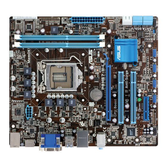
Motherboard overview 1.2.1 Motherboard layout Ensure that you install the motherboard into the chassis in the correct orientation. The edge with external ports goes to the rear part of the chassis. 21.3cm(8.4in) KB_USB56 CPU_FAN COM1 Super EATX12V 1442 MemOK! DRAM_LED USB34 LAN1_USB12 CHA_FAN... -
Page 13: Central Processing Unit (Cpu)
Contact your retailer immediately if the PnP cap is missing, or if you see any damage to the PnP cap/socket contacts/motherboard components. ASUS will shoulder the cost of repair only if the damage is shipment/transit-related. • Keep the cap after installing the motherboard. ASUS will process Return Merchandise Authorization (RMA) requests only if the motherboard comes with the cap on the LGA1155 socket. -
Page 14: Memory Configurations
2.4 Ai Tweaker menu for manual memory frequency adjustment. • For system stability, use a more efficient memory cooling system to support a full memory load (2 DIMMs) or overclocking condition. P8H67-M LE Series Motherboard Qualified Vendors Lists (QVL) DDR3-1333 MHz capability DIMM Chip... - Page 15 • • SEC 904 HCH9 Kingtiger 2GB DIMM PC3-10666 Samsung • • K4B1G0846D Kingtiger KTG2G1333PG3 • • PATRIOT PSD31G13332H • • PATRIOT PSD31G13332 Patriot PM64M8D38U-15 • • PATRIOT PSD32G13332H • • continued on the next page ASUS P8H67-M LE Series...
- Page 16 • A*: Supports one module inserted into any slot as single-channel memory configuration. • B*: Supports two modules inserted into both slots as dual-channel memory configuration. Visit the ASUS website at www.asus.com for the latest QVL. Chapter 1: Product introduction...
-
Page 17: Expansion Slots
This motherboard has a PCI Express 2.0 x4 slot that supports PCI Express x4 2.0 graphic cards complying with the PCI Express specifications. 1.5.3 PCI Express x16 slot This motherboard has a PCI Express 2.0 x16 slot that supports PCI Express x16 2.0 graphic cards complying with the PCI Express specifications. ASUS P8H67-M LE Series... -
Page 18: Jumpers
Jumpers Clear RTC RAM (3-pin CLRTC) This jumper allows you to clear the Real Time Clock (RTC) RAM in CMOS. You can clear the CMOS memory of date, time, and system setup parameters by erasing the CMOS RTC RAM data. The onboard button cell battery powers the RAM data in CMOS, which include system setup information such as system passwords. -
Page 19: Connectors
Refer to the table on the next page for the LAN port LED indicators. ACT/LINK SPEED LAN port LED indications ACT/LINK LED SPEED LED Status Description Status Description No link 10 Mbps connection ORANGE Linked ORANGE 100 Mbps connection BLINKING Data activity GREEN 1 Gbps connection LAN port ASUS P8H67-M LE Series... - Page 20 USB 2.0 ports 1 and 2. These two 4-pin Universal Serial Bus (USB) ports are available for connecting USB 2.0/1.1 devices. USB 3.0 ports 3 and 4 (for P8H67-M LE only) . These two 9-pin Universal Serial Bus (USB) ports are for USB 3.0/2.0 devices.
-
Page 21: Internal Connectors
HDMI port (for P8H67-M LE only) . This port is for a High-Definition Multimedia Interface (HDMI) connector, and is HDCP compliant allowing playback of HD DVD, Blu-ray, and other protected content. USB 2.0 ports 5 and 6. These two 4-pin Universal Serial Bus (USB) ports are available for connecting USB 2.0/1.1 devices. - Page 22 • The CPU_FAN connector supports a CPU fan of maximum 2A (24 W) fan power. Digital audio connector (4-1 pin SPDIF_OUT) [for P8H67-M LE only] This connector is for an additional Sony/Philips Digital Interface (S/PDIF) port. Connect the S/PDIF Out module cable to this connector, then install the module to a slot opening at the back of the system chassis.
- Page 23 Windows XP SP2 or later version. ® • When using hot-plug and NCQ, set the SATA Mode item in the BIOS to [AHCI Mode]. See section 2.5.4 SATA Configuration for details. ASUS P8H67-M LE Series 1-13...
- Page 24 Front panel audio connector (10-1 pin AAFP) This connector is for a chassis-mounted front panel audio I/O module that supports either HD Audio or legacy AC`97 audio standard. Connect one end of the front panel audio I/O module cable to this connector. AAFP PIN 1 PIN 1...
-
Page 25: System Panel Connector
The LPT (Line Printing Terminal) connector supports devices such as a printer. LPT standardizes as IEEE 1284, which is the parallel port interface on IBM PC-compatible computers. SLCT BUSY ACK# P8H67-M LX SLIN# INIT# ERR# STB# PIN 1 P8H67-M LX Parallel Port Connector ASUS P8H67-M LE Series 1-15... - Page 26 USB connectors (10-1 pin USB78, USB910, USB1112, USB1314 ) These connectors are for USB 2.0 ports. Connect the USB module cable to any of these connectors, then install the module to a slot opening at the back of the system chassis.
-
Page 27: Onboard Switches
If the installed DIMMs still fail to boot after the whole tuning process, the DRAM_LED lights continuously. Replace the DIMMs with ones recommended in the Memory QVL (Qualified Vendors Lists) in this user manual or on the ASUS website at www.asus.com. -
Page 28: Onboard Leds
Onboard LEDs Standby Power LED The motherboard comes with a standby power LED that lights up to indicate that the system is ON, in sleep mode, or in soft-off mode. This is a reminder that you should shut down the system and unplug the power cable before removing or plugging in any motherboard component. -
Page 29: Software Support
The contents of the Support DVD are subject to change at any time without notice. Visit the ASUS website at www.asus.com for updates. To run the Support DVD Place the Support DVD to the optical drive. -
Page 30: Chapter 2: Bios Information
BIOS in the future. Copy the original motherboard BIOS using the ASUS Update utility. 2.1.1 ASUS Update utility The ASUS Update is a utility that allows you to manage, save, and update the motherboard BIOS in Windows environment. ®... -
Page 31: Asus Crashfree Bios 3 Utility
2.1.2 ASUS CrashFree BIOS 3 utility The ASUS CrashFree BIOS 3 is an auto recovery tool that allows you to restore the BIOS file when it fails or gets corrupted during the updating process. You can restore a corrupted BIOS file using the motherboard support DVD or a USB flash drive that contains the updated BIOS file. -
Page 32: Asus Bios Updater
2.1.3 ASUS BIOS Updater The ASUS BIOS Updater allows you to update BIOS in DOS environment. This utility also allows you to copy the current BIOS file that you can use as a backup when the BIOS fails or gets corrupted during the updating process. - Page 33 The BIOS Updater backup screen appears indicating the BIOS backup process. When BIOS backup is done, press any key to return to the DOS prompt. ASUSTek BIOS Updater for DOS V1.18 Current ROM Update ROM BOARD: P8H67-M LE BOARD: Unknown VER: 0218 VER:...
-
Page 34: Updating The Bios File
Select the Load Optimized Defaults item under the Exit menu. Refer to section 2.9 Exit menu for details. • Ensure to connect all SATA hard disk drives after updating the BIOS file if you have disconnected them. ASUS P8H67-M LE Series... -
Page 35: Bios Setup Program
• The BIOS setup screens shown in this section are for reference purposes only, and may not exactly match what you see on your screen. • Visit the ASUS website at www.asus.com to download the latest BIOS file for this motherboard. -
Page 36: Bios Menu Screen
Selects the boot device priority • The boot device options vary depending on the devices you installed to the system. • The Boot Menu(F8) button is available only when the boot device is installed to the system. ASUS P8H67-M LE Series... -
Page 37: Advanced Mode
The Advanced Mode provides advanced options for experienced end-users to configure the BIOS settings. The figure below shows an example of the Advanced Mode. Refer to the following sections for the detailed configurations. To access the EZ Mode, click Exit, then select ASUS EZ Mode. Back button Menu items... -
Page 38: Main Menu
7.0.0.1095 CPU Information Genuine Intel(R) CPU 0 @ 3.10GHz Speed 3124 MHz Memory Information Total Memory 1024 MB Speed 1336 MHz System Language English System Date [Mon 11/22/2010] System Time [16:46:15] Access Level Administrator > Security ASUS P8H67-M LE Series... -
Page 39: System Language
2.3.1 System Language [English] Allows you to choose the BIOS language version from the options. Configuration options: [English] 2.3.2 System Date [Day xx/xx/xxxx] Allows you to set the system date. 2.3.3 System Time [xx:xx:xx] Allows you to set the system time. 2.3.4 Security The Security menu items allow you to change the system security settings. -
Page 40: Ai Tweaker Menu
→←: Select Screen PCH Voltage 1.050V Auto ↑↓: Select Item Enter: Select +/-: Change Opt. F1: General Help F2: Previous Values F5: Optimized Defaults F10: Save ESC: Exit Version 2.00.1201. Copyright (C) 2010 American Megatrends, Inc. 2-11 ASUS P8H67-M LE Series... -
Page 41: Memory Frequency
2.4.1 Memory Frequency [Auto] Allows you to set the memory operating frequency. Configuration options: [Auto] [DDR3-800MHz] [DDR3-1066MHz] [DDR3-1333MHz] Selecting a very high memory frequency may cause the system to become unstable! If this happens, revert to the default setting. 2.4.2 GPU Boost [OK] [OK] Select [OK] to automatically optimize the iGPU frequency. -
Page 42: Dram Voltage
CPU permanently, and setting a low voltage may make the system unstable. VCCIO Voltage [Auto] (for P8H67-M LE only) 2.4.7 Allows you to set the VCCIO voltage. The values range from 0.735V to 1.685V with a 0.005V interval. -
Page 43: Advanced Menu
Advanced menu The Advanced menu items allow you to change the settings for the CPU and other system devices. Be cautious when changing the settings of the Advanced menu items. Incorrect field values can cause the system to malfunction. EFI BIOS Utility - Advanced Mode Exit Main Ai Tweaker... - Page 44 Enhanced Halt State. [Disabled] Disables this function. CPU C1E [Enabled] [Enabled] Enables the C1E support function. This item should be enabled in order to enable the Enhanced Halt State. [Disabled] Disables this function. 2-15 ASUS P8H67-M LE Series...
-
Page 45: System Agent Configuration
CPU C3 Report [Disabled] Allows you to disable or enable the CPU C3 report to the operating system. Configuration options: [Disabled] [ACPI C-2] [ACPI C-3] CPU C6 Report [Enabled] Allows you to disable or enable the CPU C6 report to the operating system. Configuration options: [Enabled] [Disabled] 2.5.2 System Agent Configuration... -
Page 46: Usb Configuration
Enables the support for USB 3.0 devices on legacy operating systems (OS). [Disabled] Disables the function. The Legacy USB3.0 Support item shows only on P8H67-M LE. EHCI Hand-off [Disabled] [Enabled] Enables the support for operating systems without an EHCI hand-off feature. -
Page 47: Super Io Configuration (For P8H67-M Lx Only)
2.5.6 Super IO Configuration (for P8H67-M LX only) Serial Port Configuration The sub-items in this menu allow you to set the serial port configuration. Serial Port [Enabled] Allows you to enable or disable the serial port (COM). Configuration options: [Enabled] [Disabled] Change Settings [Auto] Allows you to select the Serial Port base address. - Page 48 This item appears only when you set the Realtek LAN Controller item to [Enabled] and allows you to enable or disable the Rom Help of the Realtek LAN controller. Configuration options: [Enabled] [Disabled] This following two items show only on P8H67-M LE. NEC USB 3.0 Controller [Enabled] [Enabled] Enables the NEC USB 3.0 controller.
-
Page 49: Apm
2.5.8 Restore AC Power Loss [Power Off] [Power On] The system goes into on state after an AC power loss. [Power Off] The system goes into off state after an AC power loss. [Last State] The system goes into either off or on state, whatever the system state was before the AC power loss. -
Page 50: Monitor Menu
(RPM). If the fan is not connected to the motherboard, the field shows N/A. Select Ignore if you do not wish to display the detected speed. 2.6.3 CPU Q-Fan Control [Enabled] [Disabled] Disables the CPU Q-Fan control feature. [Enabled] Enables the CPU Q-Fan control feature. 2-21 ASUS P8H67-M LE Series... -
Page 51: Chassis Q-Fan Control
CPU Fan Speed Low Limit [600 RPM] This item appears only when you enable the CPU Q-Fan Control feature and allows you to disable or set the CPU fan warning speed. Configuration options: [Ignore] [200 RPM] [300 RPM] [400 RPM] [500 RPM] [600 RPM] CPU Fan Profile [Standard] This item appears only when you enable the CPU Q-Fan Control feature and allows you to set the appropriate performance level of the CPU fan. -
Page 52: Boot Menu
[Enabled] Enables the full screen logo display feature. [Disabled] Disables the full screen logo display feature. Set this item to [Enabled] to use the ASUS MyLogo 2™ feature. 2.7.3 Option ROM Messages [Force BIOS] [Force BIOS] The third-party ROM messages will be forced to display during the boot sequence. -
Page 53: Boot Option Priorities
• To select the boot device during system startup, press <F8> when ASUS Logo appears. • To access Windows OS in Safe Mode, do any of the following: - Press <F5>... -
Page 54: Tools Menu
> ASUS EZ Flash Utility > ASUS O.C. Profile 2.8.1 ASUS EZ Flash Utility Allows you to run ASUS EZ Flash. When you press <Enter>, ASUS EZ Flash screen appears. 2.8.2 ASUS O.C. Profile This item allows you to store or load multiple BIOS settings. -
Page 55: Exit Menu
Load Optimized Defaults Save Changes & Reset Discard Changes & Exit ASUS EZ Mode Launch EFI Shell from filesystem device Load Optimized Defaults This option allows you to load the default values for each of the parameters on the Setup menus. -
Page 56: Asus Contact Information
+1-510-739-3777 +1-510-608-4555 Web site usa.asus.com Technical Support Telephone +1-812-282-2787 Support fax +1-812-284-0883 Online support support.asus.com ASUS COMPUTER GmbH (Germany and Austria) Address Harkort Str. 21-23, D-40880 Ratingen, Germany +49-2102-959911 Web site www.asus.de Online contact www.asus.de/sales Technical Support Telephone (Component) +49-1805-010923*...