Table of Contents
Advertisement
Advertisement
Table of Contents

Related Manuals for Asus P8H67-I PRO


Summary of Contents for Asus P8H67-I PRO
- Page 1 P8H67-I Series • P8H67-I PRO • P8H67-I DELUXE...
- Page 2 Product warranty or service will not be extended if: (1) the product is repaired, modified or altered, unless such repair, modification of alteration is authorized in writing by ASUS; or (2) the serial number of the product is defaced or missing.
-
Page 3: Table Of Contents
Installing an expansion card ........... 1-6 1.5.2 Configuring an expansion card ........1-6 1.5.3 PCI Express x16 slot ............1-6 1.5.4 Mini PCI Express slot (P8H67-I PRO only) ..... 1-6 Jumpers ..................1-7 Connectors ................... 1-8 1.7.1 Rear panel connectors ............ 1-8 1.7.2 Internal connectors ............ - Page 4 Contents BIOS setup program ..............2-7 Main menu .................. 2-10 2.3.1 System Language [English] ...........2-11 2.3.2 System Date [Day xx/xx/xxxx] ........2-11 2.3.3 System Time [xx:xx:xx] ..........2-11 2.3.4 Security ................2-11 Ai Tweaker menu ................ 2-12 2.4.1 Ai Overclock Tuner [Auto] ..........2-13 2.4.2 Memory Frequency [Auto] ..........
- Page 5 Option ROM Messages [Force BIOS] ......2-24 2.7.4 Setup Mode [EZ Mode] ..........2-24 2.7.5 Boot Option Priorities ............ 2-25 2.7.6 Boot Override ..............2-25 Tools menu ................. 2-25 2.8.1 ASUS EZ Flash Utility ........... 2-25 2.8.2 ASUS O.C. Profile ............2-25 Exit menu ..................2-26...
-
Page 6: Notices
This class B digital apparatus complies with Canadian ICES-003. ASUS Recycling/Takeback Services ASUS recycling and takeback programs come from our commitment to the highest standards for protecting our environment. We believe in providing solutions for you to be able to responsibly recycle our products, batteries, other components as well as the packaging materials. -
Page 7: Safety Information
Complying with the REACH (Registration, Evaluation, Authorisation, and Restriction of Chemicals) regulatory framework, we published the chemical substances in our products at ASUS REACH website at http://csr.asus.com/english/REACH.htm. DO NOT throw the motherboard in municipal waste. This product has been designed to enable proper reuse of parts and recycling. -
Page 8: About This Guide
Refer to the following sources for additional information and for product and software updates. ASUS websites The ASUS website provides updated information on ASUS hardware and software products. Refer to the ASUS contact information. Optional documentation Your product package may include optional documentation, such as warranty flyers, that may have been added by your dealer. -
Page 9: P8H67-I Series Specifications Summary
® Expansion slots 1 x PCI Express 2.0 x16 slot 1 x Mini PCI Express slot ( P8H67-I PRO only ) Graphics Supports HDMI 1.4 with max. resolution up to 1920 x 1200 @60Hz Supports DVI with max. resolution up to 1920 x 1200 @60Hz Supports D-Sub with max. - Page 10 - BT GO! ( P8H67-I DELUXE only ) ASUS Quiet Thermal Solutions - ASUS FanXpert ASUS EZ DIY - ASUS CrashFree BIOS 3 - ASUS EZ Flash 2 - ASUS MyLogo 2™ - EFI BIOS 2 x Wi-Fi antenna ports ( P8H67-I DELUXE only )
- Page 11 1 x I/O shield 1 x User Manual 1 x Support DVD Support DVD Drivers ASUS utilities ASUS Update Anti-virus software (OEM version) Form factor Mini-ITX form factor: 6.75 in x 6.75 in (17.1 cm x 17.1 cm) * Specifications are subject to change without notice.
-
Page 12: Chapter 1: Product Introduction
Before you start installing the motherboard, and hardware devices on it, check the items in your motherboard package. Refer to page xi for the list of accessories. • P8H67-I Series motherboards include P8H67-I PRO and P8H67-I DELUXE two models. The package contents vary from models. The layout illustrations in this user guide are for P8H67-I DELUXE only. -
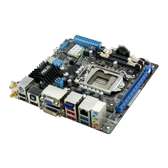
Page 13: Motherboard Overview
LGA1155 CPU socket Clear RTC RAM (3-pin CLRTC) ® USB 3.0 connector (20-1 pin USB3_34) 1-14 Digital audio connector (4-1 pin SPDIF_OUT) 1-11 DDR3 SO-DIMM slots Front panel audio connector (10-1 pin AAFP) 1-15 GPU Boost LED (O2LED2) 1-17 ASUS P8H67-I Series... -
Page 14: Central Processing Unit (Cpu)
Contact your retailer immediately if the PnP cap is missing, or if you see any damage to the PnP cap/socket contacts/motherboard components. ASUS will shoulder the cost of repair only if the damage is shipment/transit-related. • Keep the cap after installing the motherboard. ASUS will process Return Merchandise Authorization (RMA) requests only if the motherboard comes with the cap on the LGA1155 socket. -
Page 15: Memory Configurations
• • KINGSTON KVR1333D3S9/2G D1288JPNDPLD9U 1.5V • • OCZ3M13332GK 2GB(2 x 1GB) DS X43N6416AJ-13 • • OCZ3M13334GK 4GB(2 x 2GB) DS 256X8DDR3 HL • • SAMSUNG M471B5773CHS-CH9 SAMSUNG K4B2G0846C • • Transcend TS256MSK64V3N MICRON D9LGK • • ASUS P8H67-I Series... - Page 16 • 1 DIMM: Supports one module inserted into any slot as single-channel memory configuration. • 2 DIMMs: Supports one pair of modules inserted into both the black slots as one pair of dual-channel memory configuration. Visit the ASUS website at www.asus.com for the latest QVL. Chapter 1: Product introduction...
-
Page 17: Expansion Slots
This motherboard has a PCI Express 2.0 x16 slot that supports PCI Express x16 2.0 graphic cards complying with the PCI Express specifications. 1.5.4 Mini PCI Express slot (P8H67-I PRO only) This motherboard has a Mini PCI Express slot that supports Mini PCI Express cards complying with the Mini PCI Express specifications. -
Page 18: Jumpers
Jumpers Clear RTC RAM (3-pin CLRTC) This jumper allows you to clear the Real Time Clock (RTC) RAM in CMOS. You can clear the CMOS memory of date, time, and system setup parameters by erasing the CMOS RTC RAM data. The onboard button cell battery powers the RAM data in CMOS, which include system setup information such as system passwords. -
Page 19: Connectors
Bluetooth devices. • Under Windows 7 OS, to achieve the complete Bluetooth functions, download the latest ® Bluetooth driver from the ASUS support wedsite at http://support.asus.com. • Bluetooth Electrical Specification: Bluetooth specification V.2.1 compliant; Transmission rate up to 3 Mbps;... - Page 20 LAN (RJ-45) port. This port allows Gigabit connection to a Local Area Network (LAN) through a network hub. Refer to the table below for the LAN port LED indications. LAN port LED indications Speed Activity Link ACT/LINK LED SPEED LED Status Description Status...
-
Page 21: Internal Connectors
The system may become unstable or may not boot up if the power is inadequate. • If you are uncertain about the minimum power supply requirement for your system, refer to the Recommended Power Supply Wattage Calculator at http://support.asus. com/PowerSupplyCalculator/PSCalculator.aspx?SLanguage=en-us for details. ASUS P8H67-I Series... - Page 22 • The CPU_FAN connector supports a CPU fan of maximum 2A (24 W) fan power. • Only the 4-pin CPU fan and chassis fan support the ASUS FanXpert feature. Digital audio connector (4-1 pin SPDIF_OUT) This connector is for an additional Sony/Philips Digital Interface (S/PDIF) port.
- Page 23 If you installed Serial ATA hard disk drives, you can create a RAID 0, 1, 5, and 0+1(10) configurations with the Intel Matrix Storage Technology through the onboard Intel ® ® H67 chipset. SATA3G_1 SATA3G_2 P8H67-I DELUXE Intel SATA 3.0Gb/s connectors ® ASUS P8H67-I Series 1-12...
-
Page 24: System Panel Connector
• These connectors are set to [IDE Mode] by default. In IDE mode, you can connect Serial ATA boot/data hard disk drives to these connectors. If you intend to create a Serial ATA RAID set using these connectors, set the SATA Mode item in the BIOS to [RAID Mode]. See section 2.5.4 SATA Configuration for details. - Page 25 This connector is for the additional USB 3.0 ports. Connect the USB 3.0 bracket cable to this connector, then install the USB 3.0 bracket to the rear side of the chassis. If your chassis support customized front panel installation, with ASUS USB 3.0 header, you can have a front panel USB 3.0 solution.
-
Page 26: Onboard Switches
Front panel audio connector (10-1 pin AAFP) This connector is for a chassis-mounted front panel audio I/O module that supports either HD Audio or legacy AC`97 audio standard. Connect one end of the front panel audio I/O module cable to this connector. AAFP PIN 1 PIN 1... - Page 27 If the installed DIMMs still fail to boot after the whole tuning process, the DRAM_LED lights continuously. Replace the DIMMs with ones recommended in the Memory QVL (Qualified Vendors Lists) in this user manual or on the ASUS website at www.asus.com.
-
Page 28: Onboard Leds
Onboard LEDs Standby Power LED The motherboard comes with a standby power LED that lights up to indicate that the system is ON, in sleep mode, or in soft-off mode. This is a reminder that you should shut down the system and unplug the power cable before removing or plugging in any motherboard component. -
Page 29: Software Support
The contents of the Support DVD are subject to change at any time without notice. Visit the ASUS website at www.asus.com for updates. To run the Support DVD Place the Support DVD to the optical drive. -
Page 30: Asus @Vibe
64-bit XP OS. ® Launching ASUS @Vibe Install ASUS @Vibe from the motherboard support DVD. To launch ASUS @Vibe ,click Start > All Programs > ASUS > ASUS VIBE > ASUS VIBE. Visit the ASUS website at www.asusvibe.com for more details. 1-19... -
Page 31: Chapter 2: Bios Information
BIOS in the future. Copy the original motherboard BIOS using the ASUS Update utility. 2.1.1 ASUS Update utility The ASUS Update is a utility that allows you to manage, save, and update the motherboard BIOS in Windows environment. ®... -
Page 32: Asus Ez Flash 2
Follow the onscreen instructions to complete the updating process. 2.1.2 ASUS EZ Flash 2 The ASUS EZ Flash 2 feature allows you to update the BIOS without using an OS-based utility. Before you start using this utility, download the latest BIOS file from the ASUS website at www.asus.com. -
Page 33: Asus Crashfree Bios 3 Utility
2.1.3 ASUS CrashFree BIOS 3 utility The ASUS CrashFree BIOS 3 is an auto recovery tool that allows you to restore the BIOS file when it fails or gets corrupted during the updating process. You can restore a corrupted BIOS file using the motherboard support DVD or a USB flash drive that contains the updated BIOS file. -
Page 34: Asus Bios Updater
2.1.4 ASUS BIOS Updater The ASUS BIOS Updater allows you to update BIOS in DOS environment. This utility also allows you to copy the current BIOS file that you can use as a backup when the BIOS fails or gets corrupted during the updating process. - Page 35 Backing up the current BIOS To backup the current BIOS file using the BIOS Updater Ensure that the USB flash drive is not write-protected and has at least 1024KB free space to save the file. At the FreeDOS prompt, type bupdater /o[filename] and press <Enter>. D:\>bupdater /oOLDBIOS1.rom Filename Extension The [filename] is any user-assigned filename with no more than eight alphanumeric...
-
Page 36: Updating The Bios File
Select the Load Optimized Defaults item under the Exit menu. Refer to section 2.9 Exit menu for details. • Ensure to connect all SATA hard disk drives after updating the BIOS file if you have disconnected them. ASUS P8H67-I Series... -
Page 37: Bios Setup Program
• The BIOS setup screens shown in this section are for reference purposes only, and may not exactly match what you see on your screen. • Visit the ASUS website at www.asus.com to download the latest BIOS file for this motherboard. -
Page 38: Bios Menu Screen
Power Saving mode Loads optimized default Selects the boot device priority Normal mode ASUS Optimal mode Displays the system properties of the selected mode on the right hand side Selects the boot device priority • The boot device options vary depending on the devices you installed to the system. -
Page 39: Advanced Mode
The Advanced Mode provides advanced options for experienced end-users to configure the BIOS settings. The figure below shows an example of the Advanced Mode. Refer to the following sections for the detailed configurations. To access the EZ Mode, click Exit, then select ASUS EZ Mode. Back button Menu items... -
Page 40: Main Menu
7.0.0.1135 CPU Information Genuine Intel(R) CPU 0 @ 3.10GHz Speed 3100 MHz Memory Information Total Memory 2048 MB Speed 1333 MHz System Language English System Date [Mon 09/13/2010] System Time [16:46:15] Access Level Administrator > Security 2-10 ASUS P8H67-I Series... -
Page 41: System Language [English]
2.3.1 System Language [English] Allows you to choose the BIOS language version from the options. Configuration options: [English] 2.3.2 System Date [Day xx/xx/xxxx] Allows you to set the system date. 2.3.3 System Time [xx:xx:xx] Allows you to set the system time. 2.3.4 Security The Security menu items allow you to change the system security settings. -
Page 42: Ai Tweaker Menu
F1: General Help CPU PLL Voltage 1.800V Auto F2: Previous Values F5: Optimized Defaults PCH Voltage 1.050V Auto F10: Save ESC: Exit Load-Line Calibration Auto CPU Spread Spectrum Auto Version 2.00.1201. Copyright (C) 2010 American Megatrends, Inc. 2-12 ASUS P8H67-I Series... -
Page 43: Ai Overclock Tuner [Auto]
Target DRAM Speed : xxxxMHz Displays the current DRAM speed. 2.4.1 Ai Overclock Tuner [Auto] Allows you to select the CPU overclocking options to achieve the desired CPU internal frequency. Select any of these preset overclocking configuration options: [Auto] Loads the optimal settings for the system. [Manual] Allows you to individually set overclocking parameters. -
Page 44: Cpu Power Management
To offset the voltage by a positive value. [–] To offset the voltage by a negative value. CPU Voltage [Auto] Allows you to set the CPU voltage. The values range from -0.635V to +0.635V with a 0.005V interval. 2-14 ASUS P8H67-I Series... -
Page 45: Dram Voltage [Auto]
Refer to the CPU documentation before setting the CPU voltage. Setting a high voltage may damage the CPU permanently, and setting a low voltage may make the system unstable. 2.4.8 DRAM Voltage [Auto] Allows you to set the DRAM voltage. The values range from 1.185V to 2.135V with a 0.005V interval. -
Page 46: Advanced Menu
Two threads per activated core are enabled. [Disabled] Only one thread per activated core is enabled. Active Processor Cores [All] Allows you to choose the number of CPU cores to activate in each processor package. Configuration options: [All] [1] [2] [3] 2-16 ASUS P8H67-I Series... -
Page 47: System Agent Configuration
Limit CPUID Maximum [Disabled] [Enabled] Allows legacy operating systems to boot even without support for CPUs with extended CPUID functions. [Disabled] Disables this function. Execute Disable Bit [Enabled] [Enabled] Enables the No-Execution Page Protection Technology. [Disabled] Forces the XD feature flag to always return to zero (0). Intel(R) Virtualization Technology [Disabled] [Enabled] Allows a hardware platform to run multiple operating systems separately... -
Page 48: Pch Configuration
S.M.A.R.T. Status Check [Enabled] S.M.A.R.T. (Self-Monitoring, Analysis and Reporting Technology) is a monitor system. When read/write of your hard disk errors occur, this feature allows the hard disk to report warning messages during the POST. Configuration options: [Enabled] [Disabled] 2-18 ASUS P8H67-I Series... -
Page 49: Usb Configuration
2.5.5 USB Configuration The items in this menu allow you to change the USB-related features. The USB Devices item shows the auto-detected values. If no USB device is detected, the item shows None. Legacy USB Support [Enabled] [Enabled] Enables the support for USB devices on legacy operating systems (OS). [Disabled] The USB devices can be used only for the BIOS setup program. -
Page 50: Apm
Disables the PCIE devices to generate a wake event. [Enabled] Enables the PCIE devices to generate a wake event. Power On By Ring [Disabled] [Disabled] Disables Ring to generate a wake event. [Enabled] Enables Ring to generate a wake event. 2-20 ASUS P8H67-I Series... -
Page 51: Monitor Menu
Power On By RTC [Disabled] [Disabled] Disables RTC to generate a wake event. When set to [Enabled], the items RTC Alarm Date (Days) and Hour/ [Enabled] Minute/Second will become user-configurable with set values. Monitor menu The Monitor menu displays the system temperature/power status, and allows you to change the fan settings. -
Page 52: Cpu Q-Fan Control [Enabled]
This item appears only when you enable the Chassis Q-Fan Control feature and allows you to disable or set the chassis fan warning speed. Configuration options: [Ignore] [200 RPM] [300 RPM] [400 RPM] [500 RPM] [600 RPM] 2-22 ASUS P8H67-I Series... -
Page 53: Cpu Voltage, 3.3V Voltage, 5V Voltage, 12V Voltage
Chassis Fan Profile [Standard] This item appears only when you enable the Chassis Q-Fan Control feature and allows you to set the appropriate performance level of the chassis fan. [Standard] Sets to [Standard] to make the chassis fan automatically adjust depending on the chassis temperature. -
Page 54: Boot Menu
[Enabled] Enables the full screen logo display feature. [Disabled] Disables the full screen logo display feature. Set this item to [Enabled] to use the ASUS MyLogo 2™ feature. 2.7.3 Option ROM Messages [Force BIOS] [Force BIOS] The third-party ROM messages will be forced to display during the boot sequence. -
Page 55: Boot Option Priorities
• To select the boot device during system startup, press <F8> when ASUS Logo appears. • To access Windows OS in Safe Mode, press <F8> after POST. -
Page 56: Exit Menu
Load Optimized Defaults Save Changes & Reset Discard Changes & Exit ASUS EZ Mode Launch EFI Shell from filesystem device Load Optimized Defaults This option allows you to load the default values for each of the parameters on the Setup menus. -
Page 57: Asus Contact Information
+1-510-739-3777 +1-510-608-4555 Web site usa.asus.com Technical Support Telephone +1-812-282-2787 Support fax +1-812-284-0883 Online support support.asus.com ASUS COMPUTER GmbH (Germany and Austria) Address Harkort Str. 21-23, D-40880 Ratingen, Germany +49-2102-959911 Web site www.asus.de Online contact www.asus.de/sales Technical Support Telephone (Component) +49-1805-010923*...