Table of Contents
Advertisement
Advertisement
Table of Contents

Related Manuals for Asus P5V800-MX


Summary of Contents for Asus P5V800-MX
- Page 1 P5V800-MX...
- Page 2 Product warranty or service will not be extended if: (1) the product is repaired, modified or altered, unless such repair, modification of alteration is authorized in writing by ASUS; or (2) the serial number of the product is defaced or missing.
-
Page 3: Table Of Contents
Contents Notices ....................vi Safety information ................vii About this guide ................viii P5V800-MX specifications summary ........... x Chapter 1: Product introduction Chapter 1: Product introduction Chapter 1: Product introduction Chapter 1: Product introduction Chapter 1: Product introduction Welcome! ................1-2 Package contents .............. - Page 4 Creating a bootable floppy disk ......2-2 2.1.2 ASUS EZ Flash utility ..........2-3 2.1.3 AFUDOS utility ............2-4 2.1.4 ASUS CrashFree BIOS 2 utility ........ 2-6 2.1.5 ASUS Update utility ..........2-8 BIOS setup program ............2-11 2.2.2 Menu bar ............... 2-12 2.2.3...
- Page 5 Utilities menu ............3-4 3.2.4 Make Disk menu ............3-5 3.2.5 Manuals menu ............3-5 3.2.6 ASUS Contact information ........3-6 RAID configurations .............. 3-7 3.3.1 Installing hard disks ..........3-8 Creating a RAID driver disk ..........3-12 v v v v v...
-
Page 6: Notices
Notices Federal Communications Commission Statement Federal Communications Commission Statement Federal Communications Commission Statement Federal Communications Commission Statement Federal Communications Commission Statement This device complies with Part 15 of the FCC Rules. Operation is subject to the following two conditions: • This device may not cause harmful interference, and •... -
Page 7: Safety Information
Safety information Electrical safety Electrical safety Electrical safety Electrical safety Electrical safety • To prevent electrical shock hazard, disconnect the power cable from the electrical outlet before relocating the system. • When adding or removing devices to or from the system, ensure that the power cables for the devices are unplugged before the signal cables are connected. -
Page 8: About This Guide
A S U S w e b s i t e s A S U S w e b s i t e s The ASUS website provides updated information on ASUS hardware and software products. Refer to the ASUS contact information. - Page 9 Conventions used in this guide Conventions used in this guide Conventions used in this guide Conventions used in this guide Conventions used in this guide To make sure that you perform certain tasks properly, take note of the following symbols used throughout this manual. D A N G E R / W A R N I N G : D A N G E R / W A R N I N G : Information to prevent injury to yourself D A N G E R / W A R N I N G :...
-
Page 10: P5V800-Mx Specifications Summary
B I O S f e a t u r e s B I O S f e a t u r e s 4 Mb Flash ROM, AMI BIOS, PnP, WfM2.0, DMI2.0, SM BIOS 2.3, ASUS EZ Flash, CrashFree BIOS2 (continued on the next page) x x x x x... - Page 11 P5V800-MX specifications summary I n d u s t r y s t a n d a r d I n d u s t r y s t a n d a r d I n d u s t r y s t a n d a r d...
- Page 12 x i i x i i x i i x i i x i i...
- Page 13 This chapter describes the motherboard features and the new technologies it supports. Product introduction A S U S P 5 V 8 0 0 - M X A S U S P 5 V 8 0 0 - M X A S U S P 5 V 8 0 0 - M X A S U S P 5 V 8 0 0 - M X A S U S P 5 V 8 0 0 - M X...
-
Page 14: Welcome
P 5 V 8 0 0 - M X m o t h e r b o a r d ! The motherboard delivers a host of new features and latest technologies, making it another standout in the long line of ASUS quality motherboards! Before you start installing the motherboard, and hardware devices on it, check the items in your package with the list below. - Page 15 64-bit CPU support 64-bit CPU support 64-bit CPU support 64-bit CPU support 64-bit CPU support 64-bit computing, the next generation technology to replace current 32-bit architecture, delivers advanced system performance, faster memory access and increased productivity. This motherboard provides excellent compatibility and flexibility by supporting either 64-bit or 32-bit architecture.
-
Page 16: Innovative Asus Features
ASUS EZ Flash BIOS ASUS EZ Flash BIOS With the ASUS EZ Flash, you can easily update the system BIOS even before loading the operating system. No need to use a DOS-based utility or boot from a floppy disk. See page 2-3 for details. -
Page 17: Before You Proceed
SB_PWR ® Standby Powered P5V800-MX Onboard LED Power A S U S P 5 V 8 0 0 - M X A S U S P 5 V 8 0 0 - M X A S U S P 5 V 8 0 0 - M X... -
Page 18: Motherboard Overview
Motherboard overview Before you install the motherboard, study the configuration of your chassis to ensure that the motherboard fits into it. Make sure to unplug the power cord before installing or removing the motherboard. Failure to do so can cause you physical injury and damage motherboard components. -
Page 19: Motherboard Layout
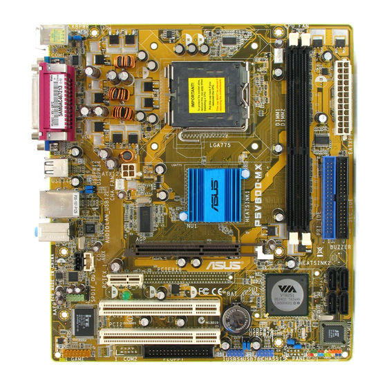
1.5.3 1.5.3 1.5.3 1.5.3 1.5.3 Motherboard layout Motherboard layout Motherboard layout Motherboard layout Motherboard layout 21.8cm (8.6in) PS/2KBMS KBPWR T: Mouse B: Keyboard COM1 CPU_FAN LGA775 USB12 ATX12V CHA_FAN USBPW12 P4M800 USBPW34 LAN_USB34 Top:Line In Center:Line Out RTL8201CL Below:Mic In ®... -
Page 20: Central Processing Unit (Cpu)
Contact your retailer immediately if the PnP cap is missing, or if you see any damage to the PnP cap/socket pins/motherboard components. ASUS will shoulder the cost of repair only if the damage is shipment/ transit-related. •... - Page 21 Press the load lever with your thumb (A) and move it to the left (B) until it is released from the retention tab. P n P C a p P n P C a p P n P C a p P n P C a p P n P C a p R e t e n t i o n t a b...
- Page 22 Close the load plate (A), then push the load lever (B) until it snaps into the retention tab. The CPU fits in only one correct orientation. DO NOT force the CPU into the socket to prevent bending the connectors on the socket and damaging the CPU! Notes on Intel Notes on Intel...
-
Page 23: Installling The Cpu Heatsink And Fan
1.6.2 1.6.2 Installling the CPU heatsink and fan Installling the CPU heatsink and fan 1.6.2 1.6.2 1.6.2 Installling the CPU heatsink and fan Installling the CPU heatsink and fan Installling the CPU heatsink and fan The Intel ® Pentium ® 4 LGA775 processor requires a specially designed heatsink and fan assembly to ensure optimum thermal condition and performance. - Page 24 CPU FAN PWR CPU FAN IN CPU FAN PWM ® P5V800-MX CPU fan connector Do not forget to connect the CPU fan connector! Hardware monitoring errors can occur if you fail to plug this connector. 1 - 1 2 1 - 1 2...
-
Page 25: Uninstalling The Cpu Heatsink And Fan
1.6.3 1.6.3 Uninstalling the CPU heatsink and fan Uninstalling the CPU heatsink and fan 1.6.3 1.6.3 1.6.3 Uninstalling the CPU heatsink and fan Uninstalling the CPU heatsink and fan Uninstalling the CPU heatsink and fan To uninstall the CPU heatsink and fan: Disconnect the CPU fan cable from the connector on the motherboard labeled... - Page 26 Remove the heatsink and fan assembly from the motherboard. Rotate each fastener clockwise to reset the orientation. N a r r o w e n d o f t h e g r o o v e N a r r o w e n d o f t h e g r o o v e N a r r o w e n d o f t h e g r o o v e N a r r o w e n d o f t h e g r o o v e N a r r o w e n d o f t h e g r o o v e...
-
Page 27: System Memory
DDR Qualified Vendors List 1.7.2 1.7.2 DDR Qualified Vendors List DDR Qualified Vendors List You can also visit the ASUS website (www.asus.com) for the latest DDR DIMM modules for this motherboard. DDR400 Qualified Vendors List DDR400 Qualified Vendors List DDR400 Qualified Vendors List... - Page 28 DDR400 Qualified Vendors List DDR400 Qualified Vendors List DDR400 Qualified Vendors List DDR400 Qualified Vendors List DDR400 Qualified Vendors List DIMM support S i z e S i z e S i z e S i z e S i z e V e n d o r V e n d o r V e n d o r...
-
Page 29: Installing A Dimm
1.7.3 1.7.3 1.7.3 1.7.3 1.7.3 Installing a DIMM Installing a DIMM Installing a DIMM Installing a DIMM Installing a DIMM Make sure to unplug the power supply before adding or removing DIMMs or other system components. Failure to do so may cause severe damage to both the motherboard and the components. -
Page 30: Expansion Slots
Expansion slots In the future, you may need to install expansion cards. The following sub-sections describe the slots and the expansion cards that they support. Make sure to unplug the power cord before adding or removing expansion cards. Failure to do so may cause you physical injury and damage motherboard components. -
Page 31: Interrupt Assignments
1.8.3 1.8.3 1.8.3 Interrupt assignments Interrupt assignments Interrupt assignments 1.8.3 1.8.3 Interrupt assignments Interrupt assignments Standard interrupt assignments Standard interrupt assignments Standard interrupt assignments Standard interrupt assignments Standard interrupt assignments I R Q I R Q P r i o r i t y P r i o r i t y S t a n d a r d F u n c t i o n S t a n d a r d F u n c t i o n... -
Page 32: Pci Slots
Install only 1.5 V or 0.8 V AGP cards on this motherboard! 3.3V AGP cards are not supported in this motherboard. ® Keyed for 1.5v P5V800-MX Accelerated Graphics Port (AGP) 1 - 2 0 1 - 2 0 1 - 2 0... -
Page 33: Jumpers
® CLRTC Normal CLEAR P5V800-MX Clear RTC RAM (Default) You do not need to clear the RTC when the system hangs due to overclocking. For system failure due to overclocking, use the C.P.R. (CPU Parameter Recall) feature. Shut down and reboot the system so the BIOS can automatically reset parameter settings to default values. - Page 34 (Default) ® P5V800-MX Keyboard power setting 2 . 2 . U S B d e v i c e w a k e - u p ( 3 - p i n U S B P W 1 2 , U S B P W 3 4 ,...
-
Page 35: 1.10 Connectors
1.10 Connectors 1.10.1 1.10.1 1.10.1 1.10.1 1.10.1 Rear panel connectors Rear panel connectors Rear panel connectors Rear panel connectors Rear panel connectors 1 . 1 . P S / 2 m o u s e p o r t ( g r e e n ) . P S / 2 m o u s e p o r t ( g r e e n ) . -
Page 36: Internal Connectors
FLOPPY PIN 1 ® NOTE: Orient the red markings on the floppy ribbon cable to PIN 1. P5V800-MX Floppy disk drive connector 1 - 2 4 1 - 2 4 1 - 2 4 1 - 2 4 1 - 2 4... - Page 37 ® PIN 1 PIN 1 P5V800-MX IDE connectors A S U S P 5 V 8 0 0 - M X A S U S P 5 V 8 0 0 - M X A S U S P 5 V 8 0 0 - M X...
- Page 38 RSATA_RXN4 RSATA_RXN2 P5V800-MX SATA connectors I m p o r t a n t n o t e s o n S e r i a l A T A I m p o r t a n t n o t e s o n S e r i a l A T A...
- Page 39 SPDIF_OUT ® SPDIFOUT P5V800-MX Digital audio connector The S/PDIF out module is purchased separately. A S U S P 5 V 8 0 0 - M X A S U S P 5 V 8 0 0 - M X...
- Page 40 Ground Ground +5 Volts PSON# Ground Ground +3 Volts -12 Volts P5V800-MX ATX power connectors +3 Volts +3 Volts 1 - 2 8 1 - 2 8 1 - 2 8 1 - 2 8 1 - 2 8 C h a p t e r 1 : P r o d u c t i n t r o d u c t i o n...
- Page 41 Left Audio Channel Left Audio Channel P5V800-MX Internal audio connectors 8 . 8 . U S B c o n n e c t o r s ( 1 0 - 1 p i n U S B 5 6 , U S B 7 8 )
- Page 42 Legacy AC’97-compliant pin definition AAFP ® P5V800-MX Analog front panel connector • Use a chassis that provides a high-definition audio front panel audio I/O to use the high-definition audio features. • The default setting of this connector is legacy AC’97 audio, if you...
-
Page 43: System Panel Connector
IDE_LED PWRSW Requires an ATX power supply. P5V800-MX System panel connector The sytem panel connector is color-coded for easy connection. Refer to the connector description below for details. S y s t e m p o w e r L E D ( G r e e n 3 - p i n P L E D ) S y s t e m p o w e r L E D ( G r e e n 3 - p i n P L E D ) •... - Page 44 1 - 3 2 1 - 3 2 1 - 3 2 1 - 3 2 1 - 3 2 C h a p t e r 1 : P r o d u c t i n t r o d u c t i o n C h a p t e r 1 : P r o d u c t i n t r o d u c t i o n C h a p t e r 1 : P r o d u c t i n t r o d u c t i o n C h a p t e r 1 : P r o d u c t i n t r o d u c t i o n...
- Page 45 This chapter tells how to change the system settings through the BIOS Setup menus. Detailed descriptions of the BIOS parameters are also provided. BIOS setup A S U S P 5 V 8 0 0 - M X A S U S P 5 V 8 0 0 - M X A S U S P 5 V 8 0 0 - M X A S U S P 5 V 8 0 0 - M X A S U S P 5 V 8 0 0 - M X...
-
Page 46: Managing And Updating Your Bios
Refer to the corresponding sections for details on these utilities. Save a copy of the original motherboard BIOS file to a bootable floppy disk in case you need to restore the BIOS in the future. Copy the original motherboard BIOS using the ASUS Update or AFUDOS utilities. 2.1.1 2.1.1 2.1.1... -
Page 47: Asus Ez Flash Utility
ASUS EZ Flash utility ASUS EZ Flash utility The ASUS EZ Flash feature allows you to update the BIOS without having to go through the long process of booting from a floppy disk and using a DOS-based utility. The EZ Flash utility is built-in the BIOS chip so it is accessible by pressing <Alt>... -
Page 48: Afudos Utility
2.1.3 2.1.3 AFUDOS utility AFUDOS utility 2.1.3 2.1.3 2.1.3 AFUDOS utility AFUDOS utility AFUDOS utility The AFUDOS utility allows you to update the BIOS file in DOS environment using a bootable floppy disk with the updated BIOS file. This utility also allows you to copy the current BIOS file that you can use as backup when the BIOS fails or gets corrupted during the updating process. - Page 49 Updating the BIOS file To update the BIOS file using the AFUDOS utility: Visit the ASUS website (www.asus.com) and download the latest BIOS file for the motherboard. Save the BIOS file to a bootable floppy disk. Write the BIOS filename on a piece of paper. You need to type the exact BIOS filename at the DOS prompt.
-
Page 50: Asus Crashfree Bios 2 Utility
ASUS CrashFree BIOS 2 utility ASUS CrashFree BIOS 2 utility The ASUS CrashFree BIOS 2 is an auto recovery tool that allows you to restore the BIOS file when it fails or gets corrupted during the updating process. You can update a corrupted BIOS file using the motherboard support CD or the floppy disk that contains the updated BIOS file. - Page 51 Restart the system after the utility completes the updating process. The recovered BIOS may not be the latest BIOS version for this motherboard. Visit the ASUS website (www.asus.com) to download the latest BIOS file. A S U S P 5 V 8 0 0 - M X...
-
Page 52: Asus Update Utility
2.1.5 2.1.5 ASUS Update utility ASUS Update utility ASUS Update utility The ASUS Update is a utility that allows you to manage, save, and update the motherboard BIOS in Windows ® environment. The ASUS Update utility allows you to: • Save the current BIOS file •... - Page 53 Updating the BIOS through the Internet Updating the BIOS through the Internet Updating the BIOS through the Internet To update the BIOS through the Internet: Launch the ASUS Update utility from the Windows ® desktop by clicking S t a r t...
- Page 54 A S U S U p d a t e A S U S U p d a t e A S U S U p d a t e. The ASUS Update main window appears. A S U S U p d a t e...
-
Page 55: Bios Setup Program
• Visit the ASUS website (www.asus.com) to download the latest BIOS file for this motherboard and . A S U S P 5 V 8 0 0 - M X... -
Page 56: Menu Bar
Legacy Diskette A [1.44M, 3.5 in] Use [+] or [-] to Primary IDE Master [ST320410A] configure the System Primary IDE Slave [ASUS CD-S520/A] Time. Secondary IDE Master [Not Detected] Secondary IDE Slave [Not Detected] Third IDE Master [Not Detected]... -
Page 57: Menu Items
For example, selecting M a i n M a i n M a i n M a i n M a i n shows the Primary IDE Slave :[ASUS CD-S340] Secondary IDE Master :[Not Detected] Secondary IDE Slave :[Not Detected] Third IDE Master :[Not Detected] Main menu items. -
Page 58: Main Menu
Legacy Diskette A [1.44M, 3.5 in] Use [+] or [-] to Primary IDE Master [ST320410A] configure the System Primary IDE Slave [ASUS CD-S520/A] Time. Secondary IDE Master [Not Detected] Secondary IDE Slave [Not Detected] Third IDE Master [Not Detected]... -
Page 59: Primary And Secondary Ide Master/Slave
2.3.4 2.3.4 2.3.4 2.3.4 2.3.4 Primary and Secondary IDE Master/Slave Primary and Secondary IDE Master/Slave Primary and Secondary IDE Master/Slave Primary and Secondary IDE Master/Slave Primary and Secondary IDE Master/Slave While entering Setup, the BIOS automatically detects the presence of IDE devices. -
Page 60: System Information
PIO Mode [Auto] PIO Mode [Auto] PIO Mode [Auto] PIO Mode [Auto] PIO Mode [Auto] Selects the PIO mode. Configuration options: [Auto] [0] [1] [2] [3] [4] DMA Mode [Auto] DMA Mode [Auto] DMA Mode [Auto] DMA Mode [Auto] DMA Mode [Auto] Selects the DMA mode. -
Page 61: Jumperfree Configuration
Advanced menu The Advanced menu items allow you to change the settings for the CPU and other system devices. Take caution when changing the settings of the Advanced menu items. Incorrect field values may cause the system to malfunction. JumperFree Configuration USB Configuration CPU Configuration Chipset... -
Page 62: Usb Configuration
Spread Spectrum [Auto] Spread Spectrum [Auto] Spread Spectrum [Auto] Spread Spectrum [Auto] Spread Spectrum [Auto] Allows you to enable or disable clock generator spread spectrum. Configuration options: [Auto] [Disabled] 2.4.2 2.4.2 USB Configuration USB Configuration 2.4.2 2.4.2 2.4.2 USB Configuration USB Configuration USB Configuration The items in this menu allows you to change the USB-related features. -
Page 63: Cpu Configuration
USB 2.0 Controller Mode [HiSpeed] USB 2.0 Controller Mode [HiSpeed] USB 2.0 Controller Mode [HiSpeed] USB 2.0 Controller Mode [HiSpeed] USB 2.0 Controller Mode [HiSpeed] Allows you to configure the USB 2.0 controller in HiSpeed (480 Mbps) or Full Speed (12 Mbps). Configuration options: [FullSpeed] [HiSpeed ] BIOS EHCI Hand-Off [Enabled] BIOS EHCI Hand-Off [Enabled] BIOS EHCI Hand-Off [Enabled]... -
Page 64: Chipset
The following item appears only when you install a processor with the Execute Disable function or Hyper-Threading. Execute Disable Function [Disabled] Execute Disable Function [Disabled] Execute Disable Function [Disabled] Execute Disable Function [Disabled] Execute Disable Function [Disabled] Enables or disables the Execute Disable function. Configuration options: [Disabled] [Enabled] Hyper-Threading Technology [Enabled] Hyper-Threading Technology [Enabled]... - Page 65 DRAM Frequency/Timing Configuration DRAM Frequency/Timing Configuration DRAM Frequency/Timing Configuration DRAM Frequency/Timing Configuration DRAM Frequency/Timing Configuration BIOS SETUP UTILITY Advanced DRAM Frequency/Timing Configuration DRAM Frequency [Auto] DRAM Timing [Auto] DRAM Command Rate [2T Command] DRAM Frequency [Auto] DRAM Frequency [Auto] DRAM Frequency [Auto] DRAM Frequency [Auto] DRAM Frequency [Auto] Sets the DDR operating frequency.
- Page 66 AGP & P2P Bridge Configuration AGP & P2P Bridge Configuration AGP & P2P Bridge Configuration AGP & P2P Bridge Configuration AGP & P2P Bridge Configuration BIOS SETUP UTILITY Advanced AGP & P2P Bridge Configuration Primary Graphics Adapter [PCI] AGP Aperture Size [128MB] AGP 3.0 Mode [8X]...
-
Page 67: Onboard Devices Configuration
SouthBridge Configuration SouthBridge Configuration SouthBridge Configuration SouthBridge Configuration SouthBridge Configuration * Serial ATA IDE Controller [SATA] * LAN Controller [Enabled] LAN Optional ROM [Disabled] * High Definition Audio [Enabled] Serial ATA IDE Controller [SATA] Serial ATA IDE Controller [SATA] Serial ATA IDE Controller [SATA] Serial ATA IDE Controller [SATA] Serial ATA IDE Controller [SATA] Allows you to set the Serial ATA mode. - Page 68 Serial Port1 Address [3F8/IRQ4] Serial Port1 Address [3F8/IRQ4] Serial Port1 Address [3F8/IRQ4] Serial Port1 Address [3F8/IRQ4] Serial Port1 Address [3F8/IRQ4] Allows you to select the Serial Port1 base address. Configuration options: [Disabled] [3F8/IRQ4] [2F8/IRQ3] [3E8/IRQ4] [2E8/IRQ3] Parallel Port Address [378] Parallel Port Address [378] Parallel Port Address [378] Parallel Port Address [378]...
-
Page 69: Pci Pnp
2.4.5 2.4.5 2.4.5 PCI PnP PCI PnP PCI PnP 2.4.5 2.4.5 PCI PnP PCI PnP The PCI PnP menu items allow you to change the advanced settings for PCI/PnP devices. The menu includes setting IRQ and DMA channel resources for either PCI/PnP or legacy ISA devices, and setting the memory size block for legacy ISA devices. -
Page 70: Power Menu
Palette Snooping [Disabled] Palette Snooping [Disabled] Palette Snooping [Disabled] Palette Snooping [Disabled] Palette Snooping [Disabled] When set to [Enabled], the pallete snooping feature informs the PCI devices that an ISA graphics device is installed in the system so that the latter can function correctly. -
Page 71: Acpi 2.0 Support [No]
2.5.3 2.5.3 2.5.3 2.5.3 2.5.3 ACPI 2.0 Support [No] ACPI 2.0 Support [No] ACPI 2.0 Support [No] ACPI 2.0 Support [No] ACPI 2.0 Support [No] Allows you to add more tables for Advanced Configuration and Power Interface (ACPI) 2.0 specifications. Configuration options: [No] [Yes] 2.5.4 2.5.4 2.5.4... -
Page 72: Hardware Monitor
Resume On PME# [Disabled] Resume On PME# [Disabled] Resume On PME# [Disabled] Resume On PME# [Disabled] Resume On PME# [Disabled] When set to [Enabled], the system enables the PME to generate a wake event while the computer is in Soft-off mode. Configuration options: [Disabled] [Enabled] Resume On PS/2 Keyboard [Disabled] Resume On PS/2 Keyboard [Disabled]... -
Page 73: Boot Menu
CPU Fan Speed [xxxxRPM] or [N/A] CPU Fan Speed [xxxxRPM] or [N/A] CPU Fan Speed [xxxxRPM] or [N/A] CPU Fan Speed [xxxxRPM] or [N/A] CPU Fan Speed [xxxxRPM] or [N/A] The onboard hardware monitor automatically detects and displays the CPU fan speed in rotations per minute (RPM). -
Page 74: Boot Device Priority
Full Screen Logo [Enabled] This allows you to enable or disable the full screen logo display feature. Configuration options: [Disabled] [Enabled] Set this item to [Enabled] to use the ASUS MyLogo2™ feature. 2 - 3 0 2 - 3 0... -
Page 75: Security
Add On ROM Display Mode [Force BIOS] Add On ROM Display Mode [Force BIOS] Add On ROM Display Mode [Force BIOS] Add On ROM Display Mode [Force BIOS] Add On ROM Display Mode [Force BIOS] Sets the display mode for option ROM. Configuration options: [Force BIOS] [Keep Current] Bootup Num-Lock [On] Bootup Num-Lock [On]... - Page 76 Change Supervisor Password Change Supervisor Password Change Supervisor Password Change Supervisor Password Change Supervisor Password Select this item to set or change the supervisor password. The Supervisor Password item on top of the screen shows the default N o t I n s t a l l e d N o t I n s t a l l e d N o t I n s t a l l e d N o t I n s t a l l e d...
- Page 77 User Access Level (Full Access] User Access Level (Full Access] User Access Level (Full Access] User Access Level (Full Access] User Access Level (Full Access] This item allows you to select the access restriction to the Setup items. Configuration options: [No Access] [View Only] [Limited] [Full Access] N o A c c e s s N o A c c e s s N o A c c e s s...
-
Page 78: Exit Menu
Exit menu The Exit menu items allow you to load the optimal or failsafe default values for the BIOS items, and save or discard your changes to the BIOS items. Exit Options Exit & Save Changes Exit & Discard Changes Discard Changes Load Setup Defaults Pressing <Esc>... - Page 79 This chapter describes the contents of the support CD that comes with the motherboard package. Software support A S U S P 5 V 8 0 0 - M X A S U S P 5 V 8 0 0 - M X A S U S P 5 V 8 0 0 - M X A S U S P 5 V 8 0 0 - M X A S U S P 5 V 8 0 0 - M X...
-
Page 80: Installing An Operating System
The support CD that came with the motherboard package contains the drivers, software applications, and utilities that you can install to avail all motherboard features. The contents of the support CD are subject to change at any time without notice. Visit the ASUS website(www.asus.com) for updates. 3.2.1 3.2.1 3.2.1 3.2.1... -
Page 81: Drivers Menu
3.2.2 3.2.2 3.2.2 3.2.2 3.2.2 Drivers menu Drivers menu Drivers menu Drivers menu Drivers menu The drivers menu shows the available device drivers if the system detects installed devices. Install the necessary drivers to activate the devices. VIA VT8251 Chipset Driver VIA VT8251 Chipset Driver VIA VT8251 Chipset Driver VIA VT8251 Chipset Driver... -
Page 82: Utilities Menu
ASUS Update ASUS Update ASUS Update ASUS Update The ASUS Update utility allows you to update the motherboard BIOS in a Windows ® environment. This utility requires an Internet connection either through a network or an Internet Service Provider (ISP). See page 2-8 for details. -
Page 83: Make Disk Menu
3.2.4 3.2.4 3.2.4 3.2.4 3.2.4 Make Disk menu Make Disk menu Make Disk menu Make Disk menu Make Disk menu The Make Disk menu allows you to make a RAID driver disk. Make VIA VT8251 32/64bit RAID Driver Disk Make VIA VT8251 32/64bit RAID Driver Disk Make VIA VT8251 32/64bit RAID Driver Disk Make VIA VT8251 32/64bit RAID Driver Disk Make VIA VT8251 32/64bit RAID Driver Disk... -
Page 84: Asus Contact Information
C o n t a c t C o n t a c t C o n t a c t tab to display the ASUS contact information. You can C o n t a c t also find this information on the inside front cover of this user guide. -
Page 85: Raid Configurations
RAID configurations The motherboard supports the following RAID configurations. R A I D 0 R A I D 0 R A I D 0 (Data striping) optimizes two identical hard disk drives to read and R A I D 0 R A I D 0 write data in parallel, interleaved stacks. -
Page 86: Installing Hard Disks
If you want to boot the system from a hard disk drive included in a RAID set, copy first the RAID driver from the support CD to a floppy disk before you install an operating system to a selected hard disk drive. Refer to section “3.6 Creating a RAID driver disk”... - Page 87 Create Array Create Array Create Array Create Array Create Array From the VIA RAID BIOS utility main menu, select C r e a t e A r r a y C r e a t e A r r a y C r e a t e A r r a y then C r e a t e A r r a y C r e a t e A r r a y...
- Page 88 Press <Y> to confirm or <N> to return to the configuration options. If you selected <Y>, proceed to step 9. Select S e l e c t D i s k D r i v e s S e l e c t D i s k D r i v e s S e l e c t D i s k D r i v e s S e l e c t D i s k D r i v e s, then press <Enter>.
- Page 89 From this point, you can auto-configure the RAID array by selecting A u t o S e t u p f o r D a t a S e c u r i t y A u t o S e t u p f o r D a t a S e c u r i t y or manually configure the RAID A u t o S e t u p f o r D a t a S e c u r i t y A u t o S e t u p f o r D a t a S e c u r i t y A u t o S e t u p f o r D a t a S e c u r i t y...
-
Page 90: Creating A Raid Driver Disk
Creating a RAID driver disk A floppy disk with the RAID driver is required when installing Windows ® 2000/XP operating system on a hard disk drive that is included in a RAID set. To create a RAID driver disk: Place the motherboard support CD into the CD-ROM drive. D r i v e r s D r i v e r s M a k e V I A V T 8 2 5 1 3 2 /...