Table of Contents
Advertisement
Advertisement
Table of Contents

Related Manuals for Asus P5N-D - Motherboard - ATX


Summary of Contents for Asus P5N-D - Motherboard - ATX
- Page 1 P5N-D...
- Page 2 Product warranty or service will not be extended if: (1) the product is repaired, modified or altered, unless such repair, modification of alteration is authorized in writing by ASUS; or (2) the serial number of the product is defaced or missing.
-
Page 3: Table Of Contents
Welcome! ..................1-1 Package contents ................. 1-1 Special features ................1-2 1.3.1 Product highlights ............1-2 1.3.2 ASUS AI Lifestyle unique features ......... 1-4 1.3.3 ASUS Intelligent Performance and Overclocking features ..........1-6 Chapter 2: Hardware information Before you proceed ..............2-1 Motherboard overview .............. -
Page 4: Contents
Managing and updating your BIOS ..........4-1 4.1.1 ASUS Update utility ............4-1 4.1.2 Creating a bootable floppy disk ........4-4 4.1.3 ASUS EZ Flash 2 utility ........... 4-5 4.1.4 Updating the BIOS ............4-6 4.1.5 Saving the current BIOS file ..........4-8 4.1.6 ASUS CrashFree BIOS 2 utility ........ - Page 5 4.6.6 Security ................. 4-38 Tools menu ................. 4-40 4.7.1 ASUS O.C. Profile ............4-40 4.7.2 ASUS EZ Flash 2 ............4-42 Exit menu ..................4-43 Chapter 5: Software support Installing an operating system ........... 5-1 Support CD information .............. 5-1 5.2.1...
- Page 6 Audio configurations ............5-11 5.3.3 ASUS PC Probe II ............5-15 5.3.4 ASUS AI Suite ............... 5-21 5.3.5 ASUS EPU Utility -- AI Gear 3 ........5-23 5.3.6 ASUS AI Nap ..............5-24 5.3.7 ASUS Q-Fan 2 .............. 5-25 5.3.8 ASUS AI Booster ............5-26 5.3.9...
-
Page 7: Notices
Notices Federal Communications Commission Statement This device complies with Part 15 of the FCC Rules. Operation is subject to the following two conditions: • This device may not cause harmful interference, and • This device must accept any interference received including interference that may cause undesired operation. -
Page 8: Safety Information
Safety information Electrical safety • To prevent electrical shock hazard, disconnect the power cable from the electrical outlet before relocating the system. • When adding or removing devices to or from the system, ensure that the power cables for the devices are unplugged before the signal cables are connected. -
Page 9: About This Guide
Refer to the following sources for additional information and for product and software updates. ASUS websites The ASUS website provides updated information on ASUS hardware and software products. Refer to the ASUS contact information. Optional documentation Your product package may include optional documentation, such as warranty flyers, that may have been added by your dealer. -
Page 10: Conventions Used In This Guide
Conventions used in this guide To make sure that you perform certain tasks properly, take note of the following symbols used throughout this manual. DANGER/WARNING: Information to prevent injury to yourself when trying to complete a task. CAUTION: Information to prevent damage to the components when trying to complete a task. -
Page 11: P5N-D Specifications Summary
Memory 4 x DIMM, max. 8GB, DDR2 800/667/533 MHz, non-ECC, un-buffered memory Dual channel memory architecture Note: Visit the ASUS website at www.asus.com for the latest Qualified Vendors List (QVL). Expansion slots 2 x PCIe 2.0 x16 - Single VGA mode: x16... -
Page 12: Specifications Summary
ASUS AI Lifestyle ASUS Power Saving Solution: Unique features - ASUS EPU (Energy Processing Unit) - ASUS AI Gear 3 (ASUS EPU utility) - ASUS AI NAP ASUS AI Lifestyle Features: - ASUS AI Direct Link ASUS Quiet Thermal Solution:... - Page 13 4-pin ATX 12V Power connector System Panel (Q-Connector) BIOS features 8 Mb Flash ROM, AWARD BIOS, PnP, DMI2.0, WfM2.0, SM BIOS 2.4, ASUS EZ Flash 2, ASUS CrashFree BIOS 2 Manageability WfM 2.0, DMI 2.0 , WOR by Ring , WOL/WOR by PME, WO USB/KB/MS, PXE &...
-
Page 15: Chapter 1: Product Introduction
This chapter describes the motherboard features and the new technologies it supports. Chapter 1: Product introduction... - Page 16 Chapter summary Welcome! ..................1-1 Package contents ................. 1-1 Special features ................1-2 ASUS P5N-D...
-
Page 17: Welcome
® The motherboard delivers a host of new features and latest technologies, making it another standout in the long line of ASUS quality motherboards! Before you start installing the motherboard, and hardware devices on it, check the items in your package with the list below. -
Page 18: Special Features
Special features 1.3.1 Product highlights Intel Core™2 Quad / Core™2 Duo / Core™2 Extreme ® CPU support This motherboard supports the latest Intel Quad-core/Core™2 processor in the ® LGA775 package and Intel’s 45nm multi-core processors. With the new Intel ® Core™... -
Page 19: High Definition Audio
Green ASUS This motherboard and its packaging comply with the European Union’s Restriction on the use of Hazardous Substances (RoHS). This is in line with the ASUS vision of creating environment-friendly and recyclable products/packaging to safeguard consumers’ health while minimizing the impact on the environment. -
Page 20: Asus Ai Lifestyle Unique Features
ASUS Motherboard's fansless concept is specifically created to provide a cool environment without all the baggage. ASUS has devoted special efforts to address the thermal issues across the motherboard, and most notably the areas that reside the CPU, power, VGA, and chipsets. - Page 21 See page 5-25 for details. ASUS EZ DIY ASUS EZ DIY feature collection provides you easy ways to install computer components, update the BIOS or back up your favorite settings. ASUS Q-Shield...
-
Page 22: Asus Intelligent Performance And Overclocking Features
The localized BIOS setup menu helps you configure your system easier and faster. See page 4-14 for details. 1.3.3 ASUS Intelligent Performance and Overclocking features Precision Tweaker 2 Allows the user to adjust the NB Voltage, FSB termination Voltage, CPU PLL Voltage and the DRAM Voltage in 0.02v steps to finetune voltages to achieve the... -
Page 23: Chapter 2: Hardware Information
This chapter lists the hardware setup procedures that you have to perform when installing system components. It includes description of the jumpers and connectors on the motherboard. Chapter 2: Hardware information... - Page 24 Chapter summary Before you proceed ..............2-1 Motherboard overview ..............2-2 Central Processing Unit (CPU) ........... 2-6 System memory ................. 2-13 Expansion slots ................2-19 Jumpers ..................2-23 Connectors ................. 2-25 ASUS P5N-D...
-
Page 25: Before You Proceed
The illustration below shows the location of the onboard LED. SB_PWR Standby Powered P5N-D Onboard LED Power ASUS P5N-D... -
Page 26: Motherboard Overview
Motherboard overview Before you install the motherboard, study the configuration of your chassis to ensure that the motherboard fits into it. Make sure to unplug the power cord before installing or removing the motherboard. Failure to do so can cause you physical injury and damage motherboard components. -
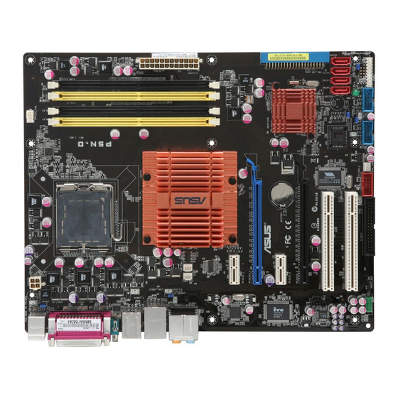
Page 27: Motherboard Layout
CMOS Power NVIDIA ® nForce 750i SLI™ ® PCIEX16_2 ALC883 PCI1 BIOS PCI2 CLRTC SB_PWR USBPW5-8 CHASSIS CHA_FAN2 FLOPPY IE1394_2 USB56 USB78 PANEL SPDIF_OUT AAFP Refer to 2.7 Connectors for more information about rear panel connectors and internal connectors. ASUS P5N-D... -
Page 28: Layout Contents
2.2.4 Layout contents Slots Page DDR2 DIMM slots 2-13 PCI slot 2-21 PCI Express x 1 slots 2-21 PCI Express 2.0 x16 slots 2-21 Jumpers Page Clear RTC RAM (3-pin CLRTC) 2-23 USB device wake-up (3-pin USBPW1-4, USBPW5-8) 2-24 Keyboard power (3-pin KBPWR) 2-24 Rear panel connectors Page... - Page 29 (4-pin CPU_FAN, 3-pin CHA_FAN1-2, 3-pin PWR_FAN) ATX power connectors (24-pin EATXPWR, 2 x 4-pin ATX12V) 2-31 Front panel audio connector (10-1 pin AAFP) 2-33 Optical drive audio connector (4-pin CD) 2-33 System panel connector (20-8 pin PANEL) 2-34 ASUS Q-Connector (system panel) 2-35 ASUS P5N-D...
-
Page 30: Central Processing Unit (Cpu)
ASUS will shoulder the cost of repair only if the damage is shipment/transit-related. • Keep the cap after installing the motherboard. ASUS will process Return Merchandise Authorization (RMA) requests only if the motherboard comes with the cap on the LGA775 socket. -
Page 31: Installing The Cpu
This side of the socket box should face you. To prevent damage to the socket pins, do not remove the PnP cap unless you are installing a CPU. Lift the load lever in the direction of the arrow to a 135º angle. ASUS P5N-D... - Page 32 Lift the load plate with your thumb and forefinger to a 100º angle (A), then push the PnP cap from the load plate window to remove (B). Load plate Alignment key Position the CPU over the socket, making sure that the gold triangle is on the bottom-left corner of the socket then fit the socket...
-
Page 33: Installing The Cpu Heatsink And Fan
CPU fan connector. Motherboard hole Fastener Narrow end of the groove Make sure to orient each fastener with the narrow end of the groove pointing outward. (The photo shows the groove shaded for emphasis.) ASUS P5N-D... - Page 34 Push down two fasteners at a time in a diagonal sequence to secure the heatsink and fan assembly in place. Connect the CPU fan cable to the connector on the motherboard labeled CPU_FAN. CPU_FAN P5N-D CPU fan connector Do not forget to connect the CPU fan connector! Hardware monitoring errors can occur if you fail to plug this connector.
- Page 35 Rotate each fastener counterclockwise. Pull up two fasteners at a time in a diagonal sequence to disengage the heatsink and fan assembly from the motherboard. Carefully remove the heatsink and fan assembly from the motherboard. ASUS P5N-D 2-11...
- Page 36 Rotate each fastener clockwise to ensure correct orientation when reinstalling. Narrow end of the groove The narrow end of the groove should point outward after resetting. (The photo shows the groove shaded for emphasis.) Refer to the documentation in the boxed or stand-alone CPU fan package for detailed information on CPU fan installation.
-
Page 37: System Memory
You may install 512 MB, 1 GB, and 2 GB unbuffered non-ECC DDR2 DIMMs into the DIMM sockets. Sockets Mode DIMM_A1 DIMM_B1 DIMM_A2 DIMM_B2 Populated Single-Channel Populated Dual-channel (1) Populated Populated Dual-channel (2) Populated Populated Populated Populated ASUS P5N-D 2-13... - Page 38 • You may install varying memory sizes in Channel A and Channel B. The system maps the total size of the lower-sized channel for the dual-channel configuration. Any excess memory from the higher-sized channel is then mapped for single-channel operation. •...
- Page 39 1024MB NANYA NT5TU64M8BE-25C NT1GT64U8HB0BY-25C • • • 1024MB NANYA NT5TU64M8CE-25D NT1GT64U8HCOBY-25D • • 512MB A3R12E3HEF641B9A05 AL6E8E63B8E1K • • • 1024MB A3R12E3HEF641B9A05 AL7E8E63B-8E1K • • 256MB TwinMOS E2508AB-GE-E 8G-24IK2-EBT • • 1024MB Elixir N2TU51280BE-25C M2Y1G64TU8HB0B-25C • • • ASUS P5N-D 2-15...
- Page 40 P5N-D Motherboard Qualified Vendors Lists (QVL) DDR2-667MHz capability Size Vendor Chip No. SS/DS Part No. DIMM support 512MB KINGSTON D6408TEBGGL3U KVR667D2N5/512 • • • 256MB KINGSTON HYB18T256800AF3S KVR667D2N5/256 • • 256MB KINGSTON 6SBI2D9DCG KVR667D2N5/256 • • 2048MB KINGSTON E1108AB-6E-E KVR667D2N5/2G •...
- Page 41 Dual-channel memory configuration. • C*: Supports four modules inserted into both the yellow and black slots as two pairs of Dual-channel memory configuration. Visit the ASUS website for the latest DDR2-800/667/533 MHz QVL. ASUS P5N-D 2-17...
-
Page 42: Installing A Dimm
2.4.3 Installing a DIMM Unplug the power supply before adding or removing DIMMs or other system components. Failure to do so can cause severe damage to both the motherboard and the components. To install a DIMM: DDR2 DIMM notch Unlock a DIMM socket by pressing the retaining clips outward. -
Page 43: Expansion Slots
IRQ” or that the cards do not need IRQ assignments. Otherwise, conflicts will arise between the two PCI groups, making the system unstable and the card inoperable. Refer to the table on the next page for details. ASUS P5N-D 2-19... -
Page 44: Interrupt Assignments
2.5.3 Interrupt assignments Standard function System timer Standard 101/102-key or Microsoft Natural PS/2 Keyboard Communications Port (COM1)* Standard floppy disk controller System CMOS/real-time clock Microsoft ACPI-compliant system PS/2 compatible mouse port Numeric data processor NVIDIA nForce PCI System Management NVIDIA GeForce 6800 Series GPU VIA OHCI Compliant IEEE 1394 Host Controller NVIDIA Network Bus Enumerator Standard Enhanced PCI to USB Host Controller... -
Page 45: Pci Slots
PCIe 2.0 devices. This motherboard supports 2 SLI-ready Express x16 graphics cards that comply with the PCI Express specifications. PCI_2 slot PCI_1 slot PCIe 2.0 x16_2 slot PCI Express x1_2 slot PCIe 2.0 x16_1 slot PCI Express x1_1 slot ASUS P5N-D 2-21... - Page 46 • We recommend that you install a VGA card on the primary (blue) PCI Express slots, and install any other PCI Express device on the PCI Express slot (black). • Connect a rear chassis fan to the chassis (CHA_FAN1 or CHA_FAN2) connector when using two graphics cards for better thermal environment.
-
Page 47: Clear Rtc Ram
You do not need to clear the RTC when the system hangs due to overclocking. For system failure due to overclocking, use the C.P.R. (CPU Parameter Recall) feature. Shut down and reboot the system so the BIOS can automatically reset parameter settings to default values. ASUS P5N-D 2-23... -
Page 48: Usb Device Wake-Up
USB device wake-up (3-pin USBPW1-4, USBPW5-8) Set these jumpers to +5V to wake up the computer from S1 sleep mode (CPU stopped, DRAM refreshed, system running in low power mode) using the connected USB devices. Set to +5VSB to wake up from S3 and S4 sleep modes. -
Page 49: Connectors
Line In port (light blue). This port connects the tape, CD, DVD player, or other audio sources. Line Out port (lime). This port connects a headphone or a speaker. In 4-channel, 6-channel, and 8-channel configuration, the function of this port becomes Front Speaker Out. ASUS P5N-D 2-25... - Page 50 Microphone port (pink). This port connects a microphone. 10. Side Speaker Out port (gray). This port connects the side speakers in an 8-channel audio configuration. Refer to the audio configuration table below for the function of the audio ports in 2, 4, 6, or 8-channel configuration.
-
Page 51: Internal Connectors
(usually zigzag) on the IDE ribbon cable to PIN 1. P5N-D IDE connector Drive jumper setting Mode of Cable connector device(s) Single device Cable-Select or Master Black Black Two devices Cable-Select Master Slave Gray Master Master Black or gray Slave Slave ASUS P5N-D 2-27... -
Page 52: Sata1 Sata2 Sata3
• Pin 20 on the IDE connector is removed to match the covered hole on the Ultra DMA cable connector. This prevents incorrect insertion when you connect the IDE cable. • Use the 80-conductor IDE cable for Ultra DMA 133/100/66 IDE devices. If any device jumper is set as “Cable-Select,”... - Page 53 Never connect a 1394 cable to the USB connectors. Doing so will damage the motherboard! You can connect the USB cable to ASUS Q-Connector (USB, blue) first, and then install the Q-Connector (USB) to the USB connector onboard. ASUS P5N-D...
- Page 54 Never connect a USB cable to the IEEE 1394a connector. Doing so will damage the motherboard! You can connect the 1394 cable to ASUS Q-Connector (1394, red) first, and then install the Q-Connector (1394) to the 1394 connector onboard. The IEEE 1394a module cable is purchased separately.
- Page 55 DO NOT place jumper caps on the fan connectors! • Only the CPU_FAN, CHA_FAN1 and CHA_FAN2 connectors support the ASUS Q-FAN 2 feature. • If you install two VGA cards, we recommend that you plug the rear chassis fan cable to the motherboard connector labeled CHA_FAN1 or CHA_FAN2 for better thermal environment.
- Page 56 • If you are uncertain about the minimum power supply requirement for your system, refer to the Recommended Power Supply Wattage Calculator at http://support.asus.com/PowerSupplyCalculator/PSCalculator. aspx?SLanguage=en-us for details. • Use of a PSU with a higher power output is recommended when configuring a system with more power-consuming devices.
- Page 57 10. Optical drive audio connector (4-pin CD) This connector allows you to receive stereo audio input from sound sources such as a CD-ROM, TV tuner, or MPEG card. Right Audio Channel Ground Ground Left Audio Channel (black) P5N-D Internal audio connector ASUS P5N-D 2-33...
-
Page 58: System Panel Connector
11. System panel connector (20-8 pin PANEL) This connector supports several chassis-mounted functions. PLED SPEAKER PANEL RESET IDE_LED PWRSW Requires an ATX power supply. P5N-D System panel connector • System power LED (2-pin PLED) This 2-pin connector is for the system power LED. Connect the chassis power LED cable to this connector. -
Page 59: Asus Q-Connector
12. ASUS Q-Connector (system panel) You can use the ASUS Q-Connector to connect/disconnect chassis front panel cables in a few steps. Refer to the instructions below to install the ASUS Q- Connector. Connect the front panel cables to the ASUS Q-Connector. -
Page 60: Installing The Optional Fan
2.7.3 Installing the optional fan Install the optional fan only if you are using a passive cooler or a water cooler. Installing the optional fan with an active CPU cooler will interfere with the airflow and destabilize the system. Fit the fan to the grooved edge of Carefully push down the fan until the heatsink. -
Page 61: Chapter 3: Powering Up
This chapter describes the power up sequence, the vocal POST messages, and ways of shutting down the system. Chapter 3: Powering up... - Page 62 Chapter summary Starting up for the first time ............3-1 Turning off the computer ............. 3-2 ASUS P5N-D...
-
Page 63: Starting Up For The First Time
Check the jumper settings and connections or call your retailer for assistance. At power on, hold down the <Delete> key to enter the BIOS Setup. Follow the instructions in Chapter 4. ASUS P5N-D P5N-D... -
Page 64: Turning Off The Computer
Turning off the computer 3.2.1 Using the OS shut down function If you are using Windows ® Click the Start button then select Turn Off Computer. Click the Turn Off button to shut down the computer. The power supply should turn off after Windows ®... -
Page 65: Chapter 4: Bios Setup
This chapter tells how to change the system settings through the BIOS Setup menus. Detailed descriptions of the BIOS parameters are also provided. Chapter 4: BIOS setup... - Page 66 Chapter summary Managing and updating your BIOS ..........4-1 BIOS setup program ..............4-10 Main menu .................. 4-14 Advanced menu ................. 4-19 Power menu ................4-30 Boot menu .................. 4-35 Tools menu ................. 4-40 Exit menu ..................4-43 ASUS P5N-D...
-
Page 67: Managing And Updating Your Bios
ASUS Update (Updates the BIOS in Windows environment.) ® ASUS EZ Flash 2 (Updates the BIOS in DOS using a floppy disk or a USB flash disk.) Award BIOS Flash Utility (Updates the BIOS in DOS mode using a bootable floppy disk.) - Page 68 To update the BIOS through the Internet: desktop by clicking Start Launch the ASUS Update utility from the Windows ® > Programs > ASUS > ASUSUpdate > ASUSUpdate. The ASUS Update main window appears. Select Update BIOS from the Select the ASUS FTP site nearest...
- Page 69 To update the BIOS through a BIOS file: desktop by clicking Start Launch the ASUS Update utility from the Windows ® > Programs > ASUS > ASUSUpdate > ASUSUpdate. The ASUS Update main window appears. Select Update BIOS from a file option from the drop-down menu, then click Next.
-
Page 70: Creating A Bootable Floppy Disk
4.1.2 Creating a bootable floppy disk Do either one of the following to create a bootable floppy disk. DOS environment a. Insert a 1.44MB floppy disk into the drive. b. At the DOS prompt, type format A:/S then press <Enter>. Windows XP environment ®... -
Page 71: Asus Ez Flash 2 Utility
4.1.3 ASUS EZ Flash 2 utility The ASUS EZ Flash 2 feature allows you to update the BIOS without having to go through the long process of booting from a floppy disk and using a DOS-based utility. The EZ Flash 2 utility is built-in the BIOS chip so it is accessible by pressing <Alt>... -
Page 72: Updating The Bios
The Basic Input/Output System (BIOS) can be updated using the AwardBIOS Flash Utility. Follow these instructions to update the BIOS using this utility. Visit the ASUS website (www.asus.com) and download the latest BIOS file for the motherboard. Save the BIOS file to a bootable floppy disk. - Page 73 Type the BIOS file name in AwardBIOS Flash Utility for ASUS V1.17 the File Name to Program (C) Phoenix Technologies Ltd. All Rights Reserved field, then press <Enter>. For C55-MCP51-P5N-D-00 DATE:10/31/2007 Flash Type - File Name to Program: P5N-D.bin Message: Do You Want To Save Bios (Y/N) Press <N>...
-
Page 74: Saving The Current Bios File
To save the current BIOS file using the AwardBIOS Flash Utility: Follow steps 1 to 6 of the AwardBIOS Flash Utility for ASUS V1.17 previous section. (C) Phoenix Technologies Ltd. All Rights Reserved Press <Y> when the utility... -
Page 75: Asus Crashfree Bios 2 Utility
4.1.6 ASUS CrashFree BIOS 2 utility The ASUS CrashFree BIOS 2 is an auto recovery tool that allows you to restore the BIOS file when it fails or gets corrupted during the updating process. You can update a corrupted BIOS file using the motherboard support CD or the floppy disk that contains the updated BIOS file. -
Page 76: Bios Setup Program
The BIOS setup screens shown in this section are for reference purposes only, and may not exactly match what you see on your screen. • Visit the ASUS website (www.asus.com) to download the latest BIOS file for this motherboard. 4-10... -
Page 77: Bios Menu Screen
• The BIOS setup screens shown in this chapter are for reference purposes only, and may not exactly match what you see on your screen. • Visit the ASUS website (www.asus.com) to download the latest BIOS information. ASUS P5N-D 4-11... -
Page 78: Legend Bar
4.2.3 Legend bar At the bottom of the Setup screen is a legend bar. The keys in the legend bar allow you to navigate through the various setup menus. The following table lists the keys found in the legend bar with their corresponding functions. Navigation Key Function <F1>... -
Page 79: Pop-Up Window
Legacy Diskette A: [1.44M, 3.5 in.] capacity and Legacy Diskette A: physical size of Primary IDE Master [ST321122A] diskette drive A. Primary IDE Slave [ASUS CDS520/A] Disabled ..[ ] SATA1 [None] 720K , 3.5 in..[ ] SATA2 [None] 1.44M, 3.5 in. -
Page 80: Main Menu
Language [English] Item Specific Help Change the day, Legacy Diskette A: [1.44M, 3.5 in.] month, year and century. Primary IDE Master [ST321122A] Primary IDE Slave [ASUS CDS520/A] SATA1 [None] SATA2 [None] SATA3 [None] SATA4 [None] HDD SMART Monitoring [Disabled] Installed Memory... -
Page 81: Primary Ide Master/Slave
If the hard disk was already formatted on a previous system, the setup BIOS may detect incorrect parameters. Select [Manual] to manually enter the IDE hard disk drive parameters. If no drive is installed select [None]. Configuration options: [None] [Auto] [Manual] ASUS P5N-D 4-15... - Page 82 Access Mode [Auto] The default [Auto] allows automatic detection of an IDE hard disk drive. Select [CHS] for this item if you set the IDE Primary Master/Slave to [Manual]. Configuration options: [CHS] [LBA] [Large] [Auto] Before attempting to configure a hard disk drive, make sure you have the correct configuration information supplied by the drive manufacturer.
-
Page 83: Sata1/2/3/4
Capacity Displays the auto-detected hard disk capacity. This item is not configurable. Cylinder Shows the number of the hard disk cylinders. This item is not configurable. ASUS P5N-D 4-17... -
Page 84: Hdd Smart Monitoring [Disabled]
Head Shows the number of the hard disk read/write heads. This item is not configurable. Landing Zone Shows the number of landing zone per track. This item is not configurable. Sector Shows the number of sectors per track. This item is not configurable. After entering the IDE hard disk drive information into BIOS, use a disk utility, such as FDISK, to partition and format new IDE hard disk drives. -
Page 85: Advanced Menu
Selct either one of the preset overclocking configuration options: Manual Allows you to individually set overclocking parameters. Auto Loads the optimal settings for the system. Standard Loads the standard settings for the system. AI Overclock Loads overclocking profiles with optimal parameters for stability when overclocking. ASUS P5N-D 4-19... -
Page 86: Voltage Control
The following item becomes user-configurable when you set AI Tuning to AI Overclock Overclock Options [Disabled] Allows you to set the overclocking options. Configuration options: [Disabled] [Overclock 5%] [Overclock 10%] [Overclock 15%] [Overclock 20%] The following items become user-configurable when you set AI Tuning to Manual System Clocks This sub-menu allows you to adjust the system frequency-related items. -
Page 87: Fsb & Memory Config
Configuration options: [533 MHz]~[3000 MHz] Actual FSB (QDR), MHz 800.0 The Actual FSB (QDR) reflects the actual CPU frequency that will take effect on a reboot. The following item becomes user-configurable when you set the FSB-Memory Clock Mode item to [Unlinked]. ASUS P5N-D 4-21... -
Page 88: Ai Net2
MEM (DDR), MHz [800] Allows you to set the Memory frequency. Adjust the value using <+> / <-> or the numeric keypad and press <Enter>. Configuration options: [400 MHz]~[2600 MHz] Actual MEM (DDR), MHz 800.0 The Actual MEM (DDR) reflects the actual memory frequency that will take effect on a reboot. -
Page 89: Cpu Configuration
Configuration options: [Disabled] [Enabled] Execute Disable Bit [Enabled] Configuration options: [Disabled] [Enabled] Virtualization Technology [Enabled] Configuration options: [Disabled] [Enabled] CPU Multiplier [8x] Configuration options: [6x] [7x] [8x] [9x] Enhanced Intel Speedstep(tm) Tech. [Disabled] Configuration options: [Disabled] [Enabled] ASUS P5N-D 4-23... -
Page 90: Chipset
4.4.4 Chipset Phoenix-AwardBIOS CMOS Setup Utility Advanced Select Menu Chipset Item Specific Help Memory Timing Setting Spread Spectrum Control LDT Frequency [5x] Memory Timing Setting Phoenix-Award BIOS CMOS Setup Utility Advanced Select Menu Memory Timing Setting Item Specific Help tCL (CAS Latency) [Auto] tRCD [Auto]... -
Page 91: Spread Spectrum Control
CPU Spread Spectrum [Auto] Configuration options: [Disabled] [Auto] SATA Spread Spectrum [Disabled] Configuration options: [Disabled] [Auto] LDT Spread Spectrum [Auto] Configuration options: [Disabled] [Center] [Down] LDT Frequency [5x] Configuration options: [1x] [2x] [3x] [4x] [5x] [6x] [7x] [8x] ASUS P5N-D 4-25... -
Page 92: Pcipnp
4.4.5 PCIPnP Phoenix-AwardBIOS CMOS Setup Utility Advanced PCIPnP Select Menu Plug & Play O/S [No] Item Specific Help Primary Display Adapter [PCI] Select Yes if you are using a Plug and Play capable operating system. Select No if you need the BIOS to configure non-boot devices. -
Page 93: Onboard Device Configuration
SATA Port 1, 2 [Enabled] Allows you to enable or disable the onchip SATA1/SATA2 port. Configuration options: [Disabled] [Enabled] SATA DMA transfer access [Enabled] Allows you to enable or disable the SATA DMA transfer access. Configuration options: [Disabled] [Enabled] ASUS P5N-D 4-27... -
Page 94: Nvraid Configuration
SATA Port 3, 4 [Enabled] Allows you to enable or disable the onchip SATA1/SATA2 port. Configuration options: [Disabled] [Enabled] SATA2 DMA transfer access [Enabled] Allows you to enable or disable the SATA2 DMA transfer access. Configuration options: [Disabled] [Enabled] IDE Prefetch Mode [Enabled] Allows you to enable or disable the IDE PIO read prefetch mode. -
Page 95: Usb Configuration
Allows you to enable or disable support for USB devices on legacy operating systems (OS). Configuration options: [Disabled] [Enabled] USB 2.0 Controller [Enabled] Allows you to enable or disable the USB 2.0 controller. Configuration options: [Disabled] [Enabled] ASUS P5N-D 4-29... -
Page 96: Power Menu
Power menu The Power menu items allow you to change the settings for the Advanced Configuration and Power Interface (ACPI) and the Advanced Power Management (APM). Select an item then press <Enter> to display the configuration options. Phoenix-AwardBIOS CMOS Setup Utility Main Advanced Power... -
Page 97: Apm Configuration
Allows you to enable or disable RTC to generate a wake event. When this item is set to [Enabled], the items Date (of Month) Alarm and Alarm Time (hh:mm) become user-configurable with set values. Configuration options: [Disabled] [Enabled] ASUS P5N-D 4-31... - Page 98 Date (of Month) Alarm [XX] To set the date of alarm, highlight this item and press <Enter> to display the Date (of Month) Alarm pop-up menu. Key-in a value within the specified range then press <Enter>. Value ‘0’ means everyday. Configuration options: [Min=0] [Max=31] Alarm Time (hh:mm) [ XX: XX: XX] To set the time of alarm, highlight this item and press <Enter>...
-
Page 99: Hardware Monitor
The Chassis Q-Fan Profile item becomes user-configurable when you enable the Chassis Q-Fan Control feature. Chassis Q-Fan Profile [Performance] Allows you to set the appropriate performance level of the Chassis Q-Fan. Configuration options: [Performance] [Optimal] [Silent] [Optimal] [Silent] ASUS P5N-D 4-33... - Page 100 Vcore Voltage, 3.3V Voltage, 5V Voltage, 12V Voltage The onboard hardware monitor automatically detects the voltage output through the onboard voltage regulators. Select [Ignored] if you do not want to detect this item. CPU Temperature [xxxºC/xxxºF] M/B Temperature [xxxºC/xxxºF] The onboard hardware monitor automatically detects and displays the motherboard and CPU temperatures.
-
Page 101: Boot Menu
Configuration options: [Removable] [Hard Disk] [CDROM] [Disabled] 4.6.2 Removable Drives Phoenix-Award BIOS CMOS Setup Utility Boot Removable Drives Select Menu 1. Floppy Disks Item Specific Help 1. Floppy Disks Allows you to assign a removable drive attached to the system. ASUS P5N-D 4-35... -
Page 102: Hard Disk Drives
4.6.3 Hard Disk Drives Phoenix-Award BIOS CMOS Setup Utility Boot Hard Disk Drives Select Menu 1. SATA X: XXXXXXXXX Item Specific Help 1. SATA X: XXXXXXXXX Allows you to assign hard disk drives attached to the system. 4.6.4 CDROM Drives Phoenix-Award BIOS CMOS Setup Utility Boot CDROM Drives... -
Page 103: Boot Settings Configuration
Typematic Rate Setting is enabled. Typematic Rate (Chars/Sec) [6] Allows you to select the rate at which a character repeats when you hold a key. Configuration options: [6] [8] [10] [12] [15] [20] [24] [30] ASUS P5N-D 4-37... -
Page 104: Security
Full Screen LOGO [Enabled] Allows you to enable or disable the full screen logo display feature. Configuration options: [Disabled] [Enabled] Make sure that the above item is set to [Enabled] if you want to use the ASUS MyLogo3™ feature. Halt On [All Errors] Allows you to set the error report type. -
Page 105: Password Check
This field requires you to enter the password before entering the BIOS setup or the system. Select [Setup] to require the password before entering the BIOS Setup. Select [System] to require the password before entering the system. Configuration options: [Setup] [System] ASUS P5N-D 4-39... -
Page 106: Tools Menu
Main Advanced Power Boot Tools Exit ASUS O.C. Profile Select Menu ASUS EZ Flash 2 Item Specific Help F1:Help ��� : Select Item -/+: Change Value F5: Setup Defaults ESC: Exit ��: Select Menu Enter: Select Sub-menu F10: Save and Exit 4.7.1... -
Page 107: Save Bios Profile
1. Insert the storage devices that contains the “xxx.CMO” file. 2. Turn on the system. 3. Enter BIOS setup program. Go to the “Tools” menu to select ASUS O.C. Profile > Load from File. Press <Enter> then the setup screen will appear. -
Page 108: Asus Ez Flash 2
The BIOS file will be saved as “xxx.CMO“. 4.7.2 ASUS EZ Flash 2 Allows you to run ASUS EZ Flash 2. When you press <Enter>, a confirmation message appears. Use the left/right arrow key to select between [Yes] or [No], then press <Enter> to confirm your choice. -
Page 109: Exit Menu
Discard Changes This option allows you to discard the selections you made and restore the previously saved values. After selecting this option, a confirmation appears. Select YES to discard any changes and load the previously saved values. ASUS P5N-D 4-43... - Page 110 4-44 Chapter 4: BIOS setup...
-
Page 111: Chapter 5: Software Support
This chapter describes the contents of the support CD that comes with the motherboard package. Chapter 5: Software support... - Page 112 Chapter summary Installing an operating system ........... 5-1 Support CD information .............. 5-1 Software information ..............5-9 RAID configurations ..............5-29 Creating a RAID driver disk ............5-37 ASUS P5N-D...
-
Page 113: Installing An Operating System
The contents of the support CD are subject to change at any time without notice. Visit the ASUS website (www.asus.com) for updates. 5.2.1 Running the support CD Place the support CD to the optical drive. -
Page 114: Drivers Menu
® ASUS EPU + AI Gear 3 Utility Installs the EPU + AI Gear 3 utility. Install this driver before the ASUS AI Suite utility. USB 2.0 Driver Installs the Universal Serial Bus 2.0 (USB 2.0) driver. Chapter 5: Software support... -
Page 115: Utilities Menu
Installs the ASUS AI Suite. ASUS Update Allows you to download the latest version of the BIOS from the ASUS website. Before using the ASUS Update, make sure that you have an Internet connection so you can connect to the ASUS website. - Page 116 You can also install the following utilities from the ASUS Superb Software Library CD. Anti-Virus Utility The anti-virus application detects and protects your computer from viruses that destroys data. You can also download the utility by clicking the Security tab.
-
Page 117: Make Disk Menu
(www.microsoft.com) for updates. ASUS Motherboard Installation Guide The ASUS Motherboard Installation Guide contains a general and clear instruction on how to install your new ASUS motherboard, FAQs, and how to maintain your 5.2.4 Make disk menu The Make disk menu contains items to create the NVIDIA SATA/RAID driver disk. -
Page 118: Manual Menu
® ® opening a user manual file. 5.2.6 ASUS Contact information Click the Contact tab to display the ASUS contact information. You can also find this information on the inside front cover of this user guide. Chapter 5: Software support... -
Page 119: Other Information
The icons on the top right corner of the screen give additional information on the motherboard and the contents of the support CD. Click an icon to display the specified information. Motherboard Info Displays the general specifications of the motherboard. Browse this CD Displays the support CD contents in graphical format. ASUS P5N-D... -
Page 120: Technical Support Form
Technical support Form Displays the ASUS Technical Support Request Form that you have to fill out when requesting technical support. Filelist Displays the contents of the support CD and a brief description of each in text format. Chapter 5: Software support... -
Page 121: Software Information
5.3.1 ASUS MyLogo2™ The ASUS MyLogo2™ utility lets you customize the boot logo. The boot logo is the image that appears on screen during the Power-On Self-Test (POST). The ASUS MyLogo2™ is automatically installed when you install the ASUS Update utility from the support CD. - Page 122 Ratio box. When the screen returns to the ASUS Update utility, flash the original BIOS to load the new boot logo. 10. After flashing the BIOS, restart the computer to display the new boot logo during POST.
-
Page 123: Audio Configurations
Audio Manager icon on the taskbar. From the taskbar, double-click on the SoundEffect icon to display the Realtek HD Audio Manager. Realtek HD Audio Manager Realtek HD Audio Manager Exit button Configuration options Minimize button Control settings window Information button ASUS P5N-D 5-11... -
Page 124: Configuration Options
Information Click the information button ( ) to display information about the audio driver version, DirectX version, audio controller, audio codec, and language setting. Minimize Click the minimize button ( ) to minimize the window. Exit Click the exit button ( ) to exit the Realtek HD Audio Manager. - Page 125 Manager, click the Audio I/O tab. Click the drop-down menu to select the channel configuration. The control settings window displays the status of connected devices. Click for analog and digital options. Click <OK> to effect the Audio I/O settings and exit ASUS P5N-D 5-13...
- Page 126 Microphone The Microphone option allows you configure your input/output settings and to check if your audio devices are connected properly. To set the Microphone options: From the Realtek HD Audio Manager, click the Microphone tab. Click the Noise Suppression option button to reduce the static background noise when recording. Click the Acoustic Echo Cancellation option button to reduce the echo from the front speakers when recording.
-
Page 127: Asus Pc Probe Ii
To launch the PC Probe II from the Windows ® > ASUS > PC Probe II > PC Probe II v1.xx.xx. The PC Probe II main window appears. After launching the application, the PC Probe II icon appears in the Windows ®... - Page 128 Button Button Functioin Opens the Configuration window Opens the Report window Opens the Desktop Management Interface window Opens the Peripheral Component Interconnect window Opens the Windows Management Instrumentation window Opens the hard disk drive, memory, CPU usage window Shows/Hides the Preference section Minimizes the application Closes the application Sensor alert...
- Page 129 You can also adjust Click to increase the threshold values using the value Config window. Click to You cannot adjust the sensor decrease threshold values in a small monitoring value panel. ASUS P5N-D 5-17...
- Page 130 Monitoring sensor alert The monitor panel turns red when a component value exceeds or is lower than the threshold value. Refer to the illustrations below. Small display Large display WMI browser Click to display the WMI (Windows Management Instrumentation) browser. This browser displays various Windows ®...
- Page 131 The left panel of the tab lists all logical drives. Click a hard disk drive to display the information on the right panel. The pie chart at the bottom of the window represents the used (blue) and the available HDD space. ASUS P5N-D 5-19...
- Page 132 Memory usage The Memory tab shows both used and available physical memory. The pie chart at the bottom of the window represents the used (blue) and the available physical memory. Configuring PC Probe II Click to view and adjust the sensor threshold values. The Config window has two tabs: Sensor/Threshold and Preference.
-
Page 133: Asus Ai Suite
5.3.4 ASUS AI Suite ASUS AI Suite allows you to launch AI Gear 3, AI N.O.S., AI Booster, AI Nap, and Q-Fan 2 utilities easily. Install the ASUS EPU + AI Gear 3 Driver before the ASUS AI Suite utility. - Page 134 Other feature buttons Click on right corner of the main window to open the monitor window. Displays the CPU/ system temperature, CPU/memory/PCIE voltage, and CPU/ chassis fan speed Displays the FSB/CPU frequency Click on right corner of the expanded window to switch the temperature from degrees Centigrade to degrees Fahrenheit.
-
Page 135: Asus Epu Utility -- Ai Gear 3
5.3.5 ASUS EPU Utility -- AI Gear 3 ASUS AI Gear 3 is a utility designed to configure and support all ASUS EPU (Energy Processing Unit) features. This easy-to-use utility provides four system performance profiles that adjusts the processor frequency and vCore voltage for different computing needs. -
Page 136: Asus Ai Nap
5.3.6 ASUS AI Nap This feature allows you to minimize the power consumption of your computer whenever you are away. Enable this feature for minimum power consumption and a more quiet system operation. After installing AI Suite from the bundled support CD, you can launch the utility by double-clicking the AI Suite icon on the Windows OS taskbar and click the AI Nap button on the AI Suite main window. -
Page 137: Asus Q-Fan 2
5.3.7 ASUS Q-Fan 2 This ASUS Q-Fan 2 Control feature allows you to set the appropriate performance level of the CPU Q-Fan 2 or the Chassis Q-Fan 2 for more efficient system operation. After enabling the Q-Fan 2 function, the fans can be set to automatically adjust depending on the temperature, to decrease fan speed, or to achieve the maximum fan speed. -
Page 138: Asus Ai Booster
5.3.8 ASUS AI Booster The ASUS AI Booster application allows you to overclock the CPU speed in WIndows environment without the hassle of booting the BIOS. ® After installing AI Suite from the bundled support CD, you can launch the utility... -
Page 139: Asus Ai Direct Link
You must first connect two computers (at least one of them is ASUS product) using a network cable, and then install the utility to both computers to avail the AI Direct Link feature. - Page 140 The authorized user has full access to this folder. The default path of the AIDirectLinkIncoming folder is C:\Program Files\ASUS\AI Direct Link. To change its location, disable the incoming folder first. Then, select disable the incoming folder first. Then, select first.
-
Page 141: Raid Configurations
RAID set. This configuration stores the same data redundantly on multiple disks that appear as a single disk on the operating system. Spanning does not deliver any advantage over using separate disks independently and does not provide fault tolerance or other RAID performance benefits. ASUS P5N-D 5-29... -
Page 142: Nvidia ® Raid Configurations
If you want to boot the system from a hard disk drive included in a RAID set, first copy the RAID driver from the Support CD to a floppy disk before you install an operating system to a selected hard disk drive. Refer to section “5.5 Creating a RAID driver disk”... -
Page 143: Entering The Nvidia Raid Utility
2.0.M XXXXXXXXXXXXXXXXXX 2.1.M XXXXXXXXXXXXXXXXXX [�] Del [F6] Back [F7] Finish [TAB] Navigate [���] Select [ENTER] Popup At the bottom of the screen are the navigation keys. These keys allow you to move through and select menu options. ASUS P5N-D 5-31... -
Page 144: Creating A Raid Volume
Creating a RAID Volume To create a RAID volume: From the NVIDIA RAID utility Define a New Array menu, select RAID Mode ® then press <Enter>. The following submenu appears. Use the up or down arrow keys to select a Mirroring RAID mode then press <Enter>. -
Page 145: Rebuilding A Raid Array
Array 1 : NVIDIA MIRROR XXX.XXG - Array Detail - RAID Mode: Mirroring Striping Width: 1 Striping Block: 64K Adapt Channel Index Disk Model Name Capacity Master XXXXXXXXXXXXXXXXX XXX.XXGB Master XXXXXXXXXXXXXXXXX XXX.XXGB [R] Rebuild [D] Delete [C] Clear Disk [ENTER] Return ASUS P5N-D 5-33... - Page 146 A new set of navigation keys is displayed on the bottom of the screen. Press <R> to rebuild a RAID array. The following screen appears. Array 1 : NVIDIA MIRROR XXX.XXG - Select Disk Inside Array - RAID Mode: Mirroring Striping Width: 1 Striping Block: 64K Adapt...
-
Page 147: Deleting A Raid Array
[N] No Press <Y> to delete array or press <N> to cancel. Take caution in using this option. All data on the RAID drives will be lost! If you selected Yes, the Define a New Array menu appears. ASUS P5N-D 5-35... -
Page 148: Clearing A Disk Data
Clearing a disk data To clear disk data: From the Array List menu, use the up or down arrow keys to select a RAID array then press <Enter>. The RAID Array details appear. Array 1 : NVIDIA MIRROR XXX.XXG - Array Detail - RAID Mode: Mirroring Striping Width: 1 Striping Block: 64K... -
Page 149: Creating A Raid Driver Disk
Press <F6> then insert the floppy disk with RAID driver into the floppy disk drive. Follow the succeeding screen instructions to complete the installation. Due to chipset limitation, the Serial ATA ports supported by the NVIDIA chipset doesn’t support Serial Optical Disk Drives (Serial ODD) under DOS. ASUS P5N-D 5-37... - Page 150 5-38 Chapter 5: Software support...
-
Page 151: Chapter 6: Nvidia Sli™ Technology Support
This chapter tells how to install SLI-ready PCI Express graphics cards. ® Chapter 6: NVIDIA SLI™ technology support... - Page 152 Chapter summary Overview ..................6-1 Dual graphics cards setup ............6-2 ASUS P5N-D...
-
Page 153: Overview
See page 2-31 for details. • The NVIDIA SLI technology supports Windows XP™ 32-bit/64bit operating ® system only. • Visit the NVIDIA zone website (http://www.nzone.com) for the latest certified graphics card and supported 3D application list. ASUS P5N-D... -
Page 154: Dual Graphics Card Setup
Dual graphics card setup 6.2.1 Installing SLI-ready graphics cards Install only identical SLI-ready graphics cards that are NVIDIA -certified. ® Different types of graphics cards will not work together properly. To install the graphics cards: Prepare two graphics cards. Each graphics card should have goldfingers for the SLI connector. - Page 155 Insert the second graphics card into the other slot (PCIEX16_2). Make sure that the card is properly seated on the slot. If required, connect an auxiliary power source to the PCI Express graphics cards. ASUS P5N-D...
- Page 156 Align and insert the SLI connector to the goldfingers on each graphics card. Make sure that the connector is firmly in place. SLI connector When installing two VGA cards using a 20-pin ATX PSU with sufficient+12v capability, we recommend that you connect the auxillary power source from the power supply to the graphics card.
-
Page 157: Installing The Device Drivers
Windows taskbar. NVIDIA Settings icon From the pop-up menu, select nView Desktop Manager then click nView Properties. From the nView Desktop Manager window, select the Desktop Management tab. Click Properties to display the Display Properties dialog box. ASUS P5N-D... - Page 158 From the Display Properties dialog box, select the Settings tab then click Advanced. Select the NVIDIA GeForce tab. Click the slider to display the following screen, then select the SLI multi-GPU item. Slider Click the Enable SLI multi-GPU check box. Click OK when done.
-
Page 159: Appendix: Cpu Features
The Appendix describes the CPU features and technologies that the motherboard supports. Appendix: CPU features... -
Page 160: A.1 Intel ® Em64T
Chapter summary Intel ® EM64T ..................A-1 Enhanced Intel SpeedStep Technology (EIST) ......A-1 ® Intel Hyper-Threading Technology ...........A-3 ® ASUS P5N-D... -
Page 161: Intel ® Em64T
32-bit operating systems. • The motherboard comes with a BIOS file that supports EM64T. You can download the latest BIOS file from the ASUS website (www.asus.com/ support/download/) if you need to update the BIOS file. See Chapter 4 for details. -
Page 162: Using The Eist
A.2.2 Using the EIST To use the EIST feature: Turn on the computer, then enter the BIOS Setup. Go to the Advanced Menu, highlight CPU Configuration, then press <Enter>. Set the Intel(R) SpeedStep (TM) Tech. item to [Automatic], then press <Enter>. -
Page 163: Intel ® Hyper-Threading Technology
Power up the system and enter the BIOS Setup. Under the Advanced Menu, make sure that the item Hyper-Threading Technology is set to [Enabled]. The BIOS item appears only if you installed a CPU that supports Hyper-Threading Technology. Restart the computer. ASUS P5N-D... - Page 164 Appendix: CPU features...