Table of Contents
Advertisement
Advertisement
Table of Contents

Related Manuals for Asus P5L 1394


Summary of Contents for Asus P5L 1394
- Page 1 P5L 1394...
- Page 2 Product warranty or service will not be extended if: (1) the product is repaired, modified or altered, unless such repair, modification of alteration is authorized in writing by ASUS; or (2) the serial number of the product is defaced or missing.
-
Page 3: Table Of Contents
How this guide is organized ..............ix Where to find more information ............ix Conventions used in this guide ..........x Typography ................x P5L 1394 specifications summary ............xi Chapter 1: Product introduction Welcome! ................1-1 Package contents ..............1-1 Special features .............. - Page 4 Managing and updating your BIOS ........4-1 4.1.1 Creating a bootable floppy disk ......4-1 4.1.2 AFUDOS utility ............4-2 4.1.3 ASUS CrashFree BIOS utility ........4-5 4.1.4 ASUS EZ Flash utility ..........4-7 4.1.5 ASUS Update utility ..........4-8 BIOS setup program ............4-11 4.2.1...
- Page 5 5.2.2 Drivers menu ............5-2 5.2.3 Utilities menu ............5-3 5.2.4 Manuals menu ............5-4 5.2.5 ASUS Contact information ........5-5 5.2.6 Other information ........... 5-5 Software information ............5-8 5.3.1 ASUS MyLogo™ ............5-8 5.3.2 Audio configurations ..........5-10...
- Page 6 Intel EM64T ................. A-1 ® Using the Intel EM64T feature ..........A-1 ® Enhanced Intel SpeedStep Technology (EIST) ....A-1 ® A.2.1 System requirements ..........A-1 A.2.2 Using the EIST ............A-2 Intel Hyper-Threading Technology ........A-3 ® Using the Hyper-Threading Technology ....... A-3...
-
Page 7: Notices
Notices Federal Communications Commission Statement This device complies with Part 15 of the FCC Rules. Operation is subject to the following two conditions: • This device may not cause harmful interference, and • This device must accept any interference received including interference that may cause undesired operation. -
Page 8: Safety Information
Safety information Electrical safety • To prevent electrical shock hazard, disconnect the power cable from the electrical outlet before relocating the system. • When adding or removing devices to or from the system, ensure that the power cables for the devices are unplugged before the signal cables are connected. -
Page 9: About This Guide
Refer to the following sources for additional information and for product and software updates. ASUS websites The ASUS website provides updated information on ASUS hardware and software products. Refer to the ASUS contact information. Optional documentation Your product package may include optional documentation, such as warranty flyers, that may have been added by your dealer. -
Page 10: Conventions Used In This Guide
Conventions used in this guide To make sure that you perform certain tasks properly, take note of the following symbols used throughout this manual. DANGER/WARNING: Information to prevent injury to yourself when trying to complete a task. CAUTION: Information to prevent damage to the components when trying to complete a task. -
Page 11: P5L 1394 Specifications Summary
P5L 1394 specifications summary LGA775 socket for Intel Core™ 2 Extreme/ ® Intel Core™ 2 Duo/Intel Pentium Extreme/Intel ® ® ® ® Pentium D/Intel Pentium 4/Intel Celeron ® ® ® ® ® processors Compatible with Intel 06 and 05A/05B processors ®... - Page 12 P5L 1394 specifications summary Special features ASUS Q-Fan ASUS EZ Flash ASUS C.P.R. ASUS CrashFree BIOS ASUS MyLogo BIOS features 4 Mb FLASH ROM, AMI BIOS, PnP, DMI2.0, SM BIOS 2.3, WfM2.0 Rear panel 1 x Parallel port 1 x LAN (RJ-45) port 4 x USB 2.0 ports...
-
Page 13: Chapter 1: Product Introduction
This chapter describes the motherboard features and the new technologies it supports. Product introduction... - Page 14 Chapter summary Welcome! ................1-1 Package contents ..............1-1 Special features ..............1-2 ASUS P5L 1394...
-
Page 15: Welcome
® The motherboard delivers a host of new features and latest technologies, making it another standout in the long line of ASUS quality motherboards! Before you start installing the motherboard, and hardware devices on it, check the items in your package with the list below. -
Page 16: Special Features
Special features 1.3.1 Product highlights Latest processor technology The motherboard comes with a 775-pin surface mount Land Grid Array (LGA) socket designed for the Intel Pentium 4 processor in the 775-land ® ® package. The motherboard supports the Intel Pentium 4 processor with ®... - Page 17 12 Mbps bandwidth on USB 1.1 to a faster 480 Mbps on USB 2.0. USB 2.0 is backward compatible with USB 1.1. See pages 2-23 and 2-27 for details. ASUS P5L 1394...
-
Page 18: Innovative Asus Features
ROM chip. See page 4-5 for details. ASUS Q-Fan technology The ASUS Q-Fan technology smartly adjusts the fan speeds according to the system loading to ensure quiet, cool, and efficient operation. See pages 4-33 for details. -
Page 19: Chapter 2: Hardware Information
This chapter lists the hardware setup procedures that you have to perform when installing system components. It includes description of the jumpers and connectors on the motherboard. Hardware information... - Page 20 Chapter summary Before you proceed .............. 2-1 Motherboard overview ............2-2 Central Processing Unit (CPU) ..........2-6 System memory ..............2-13 Expansion slots ..............2-17 Jumpers ................2-20 Connectors ................. 2-22 ASUS P5L 1394...
-
Page 21: Before You Proceed
This is a reminder that you should shut down the system and unplug the power cable before removing or plugging in any motherboard component. The illustration below shows the location of the onboard LED. SB_PWR Standby Powered Power P5L 1394 Onboard LED ASUS P5L 1394... -
Page 22: Motherboard Overview
Motherboard overview Before you install the motherboard, study the configuration of your chassis to ensure that the motherboard fits into it. Make sure to unplug the power cord before installing or removing the motherboard. Failure to do so can cause you physical injury and damage to the motherboard components. -
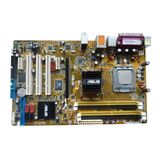
Page 23: Motherboard Layout
PCI1 JMB 360 Intel ICH7 PCI2 SATA1 SATA4 PCI3 SATA2 SATA3 6-CH Audio CLRTC PRI_EIDE USB78 SPDIF_OUT CR2032 3V Super I/O Lithium Cell PCIEX1_1 CMOS Power CHASSIS SB_PWR BIOS COM1 AAFP USB56 FLOPP Y USBPW2 SPI_J1 PANEL ASUS P5L 1394... -
Page 24: Layout Contents
2.2.4 Layout contents Slots Page DDR2 DIMM slots 2-13 PCI slots 2-19 PCI Express slots 2-19 Jumpers Page Clear RTC RAM (3-pin CLRTC) 2-20 USB Device wake-up (3-pin USBPW12) 2-21 Keyboard power (3-pin KBMSPWR) 2-21 Rear panel connectors Page PS/2 mouse port (green) 2-22 Parallel port 2-22... - Page 25 Digital audio connector (4-1 pin SPDIF_OUT) 2-27 CPU and Chassis connectors (4-pin CPU_FAN, 2-28 3-pin CHA_FAN1) Chassis intrusion connector (4-1 pin CHASSIS) 2-28 ATX power connectors (24-pin EATXPWR, 4-pin ATX12V) 2-29 System panel connector (20-1 pin PANEL) 2-30 ASUS P5L 1394...
-
Page 26: Central Processing Unit (Cpu)
Contact your retailer immediately if the PnP cap is missing, or if you see any damage to the PnP cap/socket contacts/motherboard components. ASUS shoulders the repair cost only if the damage is shipment/ transit-related. •... - Page 27 Load plate Position the CPU over the socket, making sure that the gold triangle is on the bottom-left corner of the socket. The socket alignment Alignment key key should fit into the CPU notch. Gold triangle mark ASUS P5L 1394...
- Page 28 The CPU fits in only one correct orientation. DO NOT force the CPU into the socket to prevent bending the connectors on the socket and damaging the CPU! Close the load plate (A), then push the load lever (B) until it snaps into the retention tab.
-
Page 29: Installing The Cpu Heatsink And Fan
CPU fan connector. Motherboard hole Narrow end Fastener of the groove Make sure to orient each fastener with the narrow end of the groove pointing outward. (The photo shows the groove shaded for emphasis.) ASUS P5L 1394... - Page 30 CPU FAN PWR CPU FAN IN CPU FAN PWM CHA_FAN Rotation +12V P5L 1394 Fan Connectors DO NOT forget to connect the CPU fan connector! Hardware monitoring errors can occur if you fail to plug this connector. 2-10 Chapter 2: Hardware information...
-
Page 31: Uninstalling The Cpu Heatsink And Fan
Rotate each fastener counterclockwise. Pull up two fasteners at a time in a diagonal sequence to disengage the heatsink and fan assembly from the motherboard. Carefully remove the heatsink and fan assembly from the motherboard. ASUS P5L 1394 2-11... - Page 32 Rotate each fastener clockwise to ensure correct orientation when reinstalling. Narrow end of the groove The narrow end of the groove should point outward after resetting. (The photo shows the groove shaded for emphasis.) Refer to the documentation in the boxed or stand-alone CPU fan package for detailed information on CPU fan installation.
-
Page 33: System Memory
240-pin footprint compared to the 184-pin DDR DIMM. DDR2 DIMMs are notched differently to prevent installation on a DDR DIMM socket. The figure illustrates the location of the DDR2 DIMM sockets: P5L 1394 240-pin DDR2 DIMM Sockets Channel Sockets... - Page 34 Qualified Vendors Lists (QVL) DDR2-533 DIMM support Size Vendor Model Brand Side(s) Component 512MB ELPIDA EBE51ED8ABFA-5C-E ELPIDA E5108AB-5C-E • 256MB HYNIX HYMP532U64BP6-C4 AB Hynix HY5PS121621BFP-C4 • • • 1024MB HYNIX HYMP512U728-C4 AA Hynix HY5PS12821 • 512MB INFINEON HYS64T64000GU-3.7-A INFINEON HYB18T512 •...
- Page 35 Dual‑channel memory configuration. Supports two pairs of modules inserted into the yellow and black slots as two pairs of Dual‑channel memory configuration. Visit the ASUS website for the latest DDR2-533/667 MHz QVL.. ASUS P5L 1394 2-15...
-
Page 36: Installing A Dimm
2.4.3 Installing a DIMM Unplug the power supply before adding or removing DIMMs or other system components. Failure to do so can cause severe damage to both the motherboard and the components. To install a DIMM: DDR2 DIMM notch Unlock a DIMM socket by pressing the retaining clips outward. -
Page 37: Expansion Slots
“Share IRQ” or that the cards do not need IRQ assignments. Otherwise, conflicts will arise between the two PCI groups, making the system unstable and the card inoperable. Refer to the table on the next page for details. ASUS P5L 1394 2-17... -
Page 38: Interrupt Assignments
2.5.3 Interrupt assignments Standard interrupt assignments Priority Standard Function System Timer Keyboard Controller — Re-direct to IRQ#9 — Communications Port (COM1)* IRQ holder for PCI steering* Floppy Disk Controller Printer Port (LPT1)* System CMOS/Real Time Clock IRQ holder for PCI steering* IRQ holder for PCI steering* IRQ holder for PCI steering* PS/2 Compatible Mouse Port*... -
Page 39: Pci Slots
PCI Express x1 slots This motherboard supports PCI Express x1 network cards, SCSI cards and other cards that comply with the PCI Express specifications. The following figure shows a network card installed on the PCI Express x1 slot. ASUS P5L 1394 2-19... -
Page 40: Jumpers
Normal Clear CMOS (Default) P5L 1394 Clear RTC RAM You do not need to clear the RTC when the system hangs due to overclocking. For system failure due to overclocking, use the C.P.R. (CPU Parameter Recall) feature. Shut down and reboot the system so the BIOS can automatically restore parameter settings to default values. - Page 41 S3 and S4 sleep modes (no power to CPU, DRAM in slow refresh, power supply in reduced power mode). USBPW1234 USBPW5678 P5L 1394 USB Device Wake Up • The USB device wake-up feature requires a power supply that can provide 500mA on the +5VSB lead for each USB port; otherwise, the system would not power up.
-
Page 42: Connectors
Connectors 2.7.1 Rear panel connectors PS/2 mouse port (green). This port is for a PS/2 mouse. Parallel port. This 25-pin port connects a parallel printer, a scanner, or other devices. IEEE 1394a port. This 6-pin IEEE 1394 port provides high-speed connectivity for audio/video devices, storage peripherals, PCs, or portable devices. - Page 43 10. External SATA port. This port connects to an Serial ATA hard disk drive. 11. Coaxial S/PDIF Out port. This port connects an external audio output device via a coaxial S/PDIF cable. 12. PS/2 keyboard port (purple). This port is for a PS/2 keyboard. ASUS P5L 1394 2-23...
-
Page 44: Internal Connectors
IDE cable. • Use the 80-conductor IDE cable for Ultra DMA 100/66 IDE devices. PRI_IDE PIN1 NOTE: Orient the red markings (usually zigzag) on the ID ribbon cable to PIN 1. P5L 1394 IDE Connector 2-24 Chapter 2: Hardware information... -
Page 45: Serial Ata Hard Disk Drive Connection
SATA1 SATA4 SATA2 SATA3 P5L 1394 SATA Connectors Important note on Serial ATA When using the connectors in Standard IDE mode, connect the primary (boot) hard disk drive to the SATA1 or SATA2 connector. Refer to the table below for the recommended SATA hard disk drive connections. - Page 46 Right Audio Channel Ground Ground Left Audio Channel P5L 1394 Internal Audio Connector Front panel audio connector (10-1 pin AAFP) This connector is for a chassis-mounted front panel audio I/O module that supports HD Audio or legacy AC´97 audio standard.
- Page 47 USB 2.0 specification that supports up to 480 Mbps connection speed. USB78 USB56 P5L 1394 USB 2.0 Connectors The motherboard do not bundle the module. Digital audio connector (4-1 pin SPDIF_OUT) This connector is for an additional Sony/Philips Digital Interface (S/ PDIF) port(s).
-
Page 48: Cpu And Chassis Fan Connectors
Rotation +12V P5L 1394 Fan Connectors Only the CPU_FAN connector supports the ASUS Q-Fan feature. Chassis intrusion connector (4-1 pin CHASSIS) This connector is for a chassis-mounted intrusion detection sensor or switch. Connect one end of the chassis intrusion sensor or switch cable to this connector. - Page 49 +12 Volts +5 Volts +5V Standby +5 Volts Power OK -5 Volts Ground Ground +5 Volts Ground Ground Ground +5 Volts PSON# Ground Ground P5L 1394 ATX Power Connector +3 Volts -12 Volts +3 Volts +3 Volts ASUS P5L 1394 2-29...
-
Page 50: System Panel Connector
IDE_LED PWRSW Requires an ATX power supply System Panel Connector P5L 1394 • System power LED (2-pin PLED) This 2-pin connector is for the system power LED. Connect the chassis power LED cable to this connector. The system power LED lights up when you turn on the system power, and blinks when the system is in sleep mode. - Page 51 Q-Connector (System panel) ASUS Q-Connector allows you to easily to connect the chassis front panel cables to the motherboard. Perform these steps to install ASUS Q- Connector. Step 1 Connect the front panel cables to their respective connectors on the ASUS Q-Connector.
- Page 52 2-32 Chapter 2: Hardware information...
-
Page 53: Chapter 3: Powering Up
This chapter describes the power up sequence, the vocal POST messages, and ways of shutting down the system. Powering up... - Page 54 Chapter summary Starting up for the first time ..........3-1 Powering off the computer ........... 3-2 ASUS P5L 1394...
-
Page 55: Starting Up For The First Time
Two continuous beeps followed by Floppy controller failure two short beeps Two continuous beeps followed by Hardware component failure four short beeps At power on, hold down the <Del> key to enter the BIOS Setup. Follow the instructions in Chapter 4. ASUS P5L 1394... -
Page 56: Powering Off The Computer
Powering off the computer 3.2.1 Using the OS shut down function If you are using Windows 2000: ® Click the Start button then click Shut Down... Make sure that the Shut Down option button is selected, then click the OK button to shut down the computer. The power supply should turn off after Windows shuts down. -
Page 57: Chapter 4: Bios Setup
This chapter tells how to change the system settings through the BIOS Setup menus. Detailed descriptions of the BIOS parameters are also provided. BIOS setup... - Page 58 1. Introduction Chapter summary Managing and updating your BIOS ........4-1 BIOS setup program ............4-11 Main menu ................4-14 Advanced menu ..............4-20 Power menu ................ 4-30 Boot menu ................4-35 Exit menu ................4-39...
-
Page 59: Managing And Updating Your Bios
ASUS CrashFree BIOS 2 (Updates the BIOS using a bootable floppy disk or the motherboard support CD when the BIOS file fails or gets corrupted.) ASUS EZ Flash (Updates the BIOS in DOS mode using a floppy disk or the motherboard support CD.) ASUS Update (Updates the BIOS in Windows environment.) -
Page 60: Afudos Utility
Windows 2000 environment ® To create a set of boot disks for Windows 2000: ® a. Insert a formatted, high density 1.44 MB floppy disk into the drive. b. Insert the Windows 2000 CD to the optical drive. ® c. Click Start, then select Run. d. -
Page 61: Updating The Bios File
Updating the BIOS file To update the BIOS file using the AFUDOS utility: Visit the ASUS website (www.asus.com) and download the latest BIOS file for the motherboard. Save the BIOS file to a bootable floppy disk. Write the BIOS filename on a piece of paper. You need to type the exact BIOS filename at the DOS prompt. - Page 62 The utility verifies the file and starts updating the BIOS. A:\>afudos /iP5L1394.ROM AMI Firmware Update Utility - Version 1.19 Copyright (C) 2003 American Megatrends, Inc. All rights reserved. WARNING!! Do not turn off power during flash BIOS Reading file ..done Erasing flash ..
-
Page 63: Asus Crashfree Bios Utility
4.1.3 ASUS CrashFree BIOS utility The ASUS CrashFree BIOS is an auto recovery tool that allows you to restore the BIOS file when it fails or gets corrupted during the updating process. You can update a corrupted BIOS file using the motherboard support CD or the floppy disk that contains the updated BIOS file. -
Page 64: Recovering The Bios From The Support Cd
Restart the system after the utility completes the updating process. The recovered BIOS may not be the latest BIOS version for this motherboard. Visit the ASUS website (www.asus.com) to download the latest BIOS file. Chapter 4: BIOS setup... -
Page 65: Asus Ez Flash Utility
4.1.4 ASUS EZ Flash utility The ASUS EZ Flash feature allows you to update the BIOS without having to go through the long process of booting from a floppy disk and using a DOS-based utility. The EZ Flash utility is built-in the BIOS chip so it is accessible by pressing <Alt>... -
Page 66: Asus Update Utility
4.1.5 ASUS Update utility The ASUS Update is a utility that allows you to manage, save, and update the motherboard BIOS in Windows environment. The ASUS Update utility ® allows you to: • Save the current BIOS file • Download the latest BIOS file from the Internet •... -
Page 67: Updating The Bios Through The Internet
To update the BIOS through the Internet: Launch the ASUS Update utility from the Windows desktop by clicking ® Start > Programs > ASUS > ASUSUpdate > ASUSUpdate. The ASUS Update main window appears. Select Update BIOS from Select the ASUS FTP site... -
Page 68: Updating The Bios Through A Bios File
To update the BIOS through a BIOS file: Launch the ASUS Update utility from the Windows desktop by ® clicking Start > Programs > ASUS > ASUSUpdate > ASUSUpdate. The ASUS Update main window appears. Select Update BIOS from a file option from the drop-down menu, then click Next. -
Page 69: Bios Setup Program
The BIOS setup screens shown in this section are for reference purposes only, and may not exactly match what you see on your screen. • Visit the ASUS website (www.asus.com) to download the latest BIOS file for this motherboard. ASUS P5L 1394 4-11... -
Page 70: Bios Menu Screen
[SHIFT-TAB] to Legacy Diskette A [1.44M, 3.5 in] select a field. Primary IDE Master [ST320413A] Use [+] or [-] to Primary IDE Slave [ASUS CD-S520/A] configure system time. SATA 1 [Not Detected] SATA 2 [Not Detected] SATA 3 [Not Detected]... -
Page 71: Menu Items
/<Page Down> keys to display the Exit other items on the screen. Pop-up window 4.2.9 General help Scroll bar At the top right corner of the menu screen is a brief description of the selected item. ASUS P5L 1394 4-13... -
Page 72: Main Menu
[Thu 09/22/2005] Legacy Diskette A [1.44M, 3.5 in] select a field. Primary IDE Master [ST320413A] Use [+] or [-] to Primary IDE Slave [ASUS CD-S520/A] configure system time. SATA 1 [Not Detected] SATA 2 [Not Detected] SATA 3 [Not Detected]... -
Page 73: Primary Ide Master/Slave
When set to [Disabled], the data transfer from and to the device occurs one sector at a time. Configuration options: [Disabled] [Auto] ASUS P5L 1394 4-15... -
Page 74: Sata 1, 2, 3, 4
PIO Mode [Auto] Selects the PIO mode. Configuration options: [Auto] [0] [1] [2] [3] [4] DMA Mode [Auto] Selects the DMA mode. Configuration options: [Auto] [SWDMA0] [SWDMA1] [SWDMA2] [MWDMA0] [MWDMA1] [MWDMA2] [UDMA0] [UDMA1] [UDMA2] [UDMA3] [UDMA4] [UDMA5] SMART Monitoring [Auto] Sets the Smart Monitoring, Analysis, and Reporting Technology. - Page 75 [MWDMA0] [MWDMA1] [MWDMA2] [UDMA0] [UDMA1] [UDMA2] [UDMA3] [UDMA4] [UDMA5] SMART Monitoring [Auto] Sets the Smart Monitoring, Analysis, and Reporting Technology. Configuration options: [Auto] [Disabled] [Enabled] 32Bit Data Transfer [Disabled] Enables or disables 32-bit data transfer. Configuration options: [Disabled] [Enabled] ASUS P5L 1394 4-17...
-
Page 76: Ide Configuration
4.3.6 IDE Configuration The items in this menu allow you to set or change the configurations for the IDE devices installed in the system. Select an item then press <Enter> if you wish to configure the item. IDE Configuration When in AHCI/ RAID mode SATA Onboard IDE Operate Mode [Enhanced Mode]... -
Page 77: System Information
Select Item Change Option General Help Save and Exit Exit AMI BIOS Displays the auto-detected BIOS information. Processor Displays the auto‑detected CPU specification. System Memory Displays the auto-detected total, appropriated (in use), and available system memory. ASUS P5L 1394 4-19... -
Page 78: Advanced Menu
Advanced menu The Advanced menu items allow you to change the settings for the CPU and other system devices. Take caution when changing the settings of the Advanced menu items. Incorrect field values can cause system malfunction. JumperFree Configuration Adjust system USB Configuration frequency/voltage. - Page 79 Allows you to set the PCI Express frequency. This item is set to [Auto] by default. Configuration options: [Auto] [90] [91]...[150] PCI Clock Synchronization Mode [Auto] Allows you to synchronize the PCI frequency with the PCI Express or CPU frequency. Configuration options: [33 MHz] [Auto] ASUS P5L 1394 4-21...
- Page 80 Spread Spectrum [Auto] Enables or disables the clock generator spectrum. Configuration options: [Auto] [Disabled] [Enabled] Memory Voltage [Auto] Allows you to select the DDR2 reference voltage. Configuration options: [Auto] [1.80V] [1.90V] [1.95V] [2.00V] Refer to the DDR2 documentation before adjusting the memory voltage. Setting a very high memory voltage may damage the memory module(s)! CPU VCore Voltage [Auto] Allows you to select the CPU VCore voltage.
-
Page 81: Usb Configuration
Allows you to configure the USB 2.0 controller in HiSpeed (480Mbps) or Full Speed (12 Mbps). Configuration options: [HiSpeed] [FullSpeed] BIOS EHCI Hand-Off [Disabled] Allows you to enable support for operating systems without an EHCI hand- off feature. Configuration options: [Disabled] [Enabled] ASUS P5L 1394 4-23... -
Page 82: Cpu Configuration
4.4.3 CPU Configuration The items in this menu show the CPU-related information that the BIOS automatically detects. Configure Advanced CPU settings Sets the ratio between CPU Core Manufacturer: Intel Clock and the FSB Brand String: Genuine Intel(R) CPU 3.20GHz Frequency. Frequency : 3200 MHz NOTE: If an invalid... - Page 83 Set this item to [Disabled] if you do not want to use the EIST. Configuration options: [Automatic] [Disabled] • Refer to the Appendix for details on how to use the EIST feature. • The motherboard comes with a BIOS file that supports EIST. ASUS P5L 1394 4-25...
-
Page 84: Chipset
4.4.4 Chipset The Chipset menu allows you to change the advanced chipset settings. Select an item then press <Enter> to display the sub-menu. Advanced Chipset Settings Enable or disable DRAM timing. Configure DRAM Timing by SPD [Enabled] Boot Graphic Adapter Priori [PCI Express/PCI] Select Screen Select Item... -
Page 85: Onboard Devices Configuration
LAN Option ROM [Disabled] This item allows you to enable or disable the option ROM in the onboard LAN controller. This item appears only when the Onboard PCIEX GbE LAN item is set to Enabled. Configuration options: [Disabled] [Enabled] ASUS P5L 1394 4-27... - Page 86 OnBoard External-SATA [Enabled] Allows you to enable or disable the JMicron SATA controller. Configuration options: [Enabled] [Disabled] E-SATA Operation Mode [IDE] Sets the external SATA operation mode. Configuration options: [IDE] [RAID] Serial Port1 Address [3F8/IRQ4] Allows you to select the Serial Port1 base address. Configuration options: [Disabled] [3F8/IRQ4] [2F8/IRQ3] [3E8/IRQ4] [2E8/IRQ3] Parallel Port Address [378]...
-
Page 87: Pci Pnp
Palette Snooping [Disabled] When set to [Enabled], the pallete snooping feature informs the PCI devices that an ISA graphics device is installed in the system so that the latter can function correctly. Configuration options: [Disabled] [Enabled] ASUS P5L 1394 4-29... -
Page 88: Power Menu
IRQ-xx assigned to [PCI Device] When set to [PCI Device], the specific IRQ is free for use of PCI/PnP devices. When set to [Reserved], the IRQ is reserved for legacy ISA devices. Configuration options: [PCI Device] [Reserved] Power menu The Power menu items allow you to change the settings for the ACPI and Advanced Power Management (APM) features. -
Page 89: Apm Configuration
Configuration options: [Everyday] [1] [2] [3]...[31] RTC Alarm Hour [12] To set the alarm hour, highlight this item and press the <+> or <-> key to make the selection. Configuration options: [00] [1]...[23] ASUS P5L 1394 4-31... - Page 90 RTC Alarm Minute [30] To set the alarm minute, highlight this item and press the <+> or <‑> key to make the selection. Configuration options: [00] [1]...[59] RTC Alarm Second [30] To set the alarm second, highlight this item and press the <+> or <‑>...
-
Page 91: Hardware Monitor
(RPM). If the fan is not connected to the motherboard, the field shows N/A. CPU Q-Fan Control [Disabled] Allows you to enable or disable the ASUS Q-Fan feature that smartly adjusts the fan speeds for more efficient system operation. Configuration options: [Disabled] [Enabled] The CPU Fan Profile Mode item appears when you enable the CPU Q-Fan Control feature. - Page 92 Chassis Fan1 Speed (RPM) [xxxxRPM] or [N/A] The onboard hardware monitor automatically detects and displays the chassis fan speed in rotations per minute (RPM). If the fan is not connected to the chassis, the specific field shows N/A. VCORE Voltage, 3.3V Voltage, 5V Voltage, 12V Voltage The onboard hardware monitor automatically detects the voltage output through the onboard voltage regulators.
-
Page 93: Boot Menu
These items specify the boot device priority sequence from the available devices. The number of device items that appears on the screen depends on the number of devices installed in the system. Configuration options: [xxxxx Drive] [Disabled] ASUS P5L 1394 4-35... -
Page 94: Boot Settings Configuration
Allows you to enable or disable the full screen logo display feature. Configuration options: [Disabled] [Enabled] Set this item to [Enabled] to use the ASUS MyLogo2™ feature. Add On ROM Display Mode [Force BIOS] Sets the display mode for option ROM. -
Page 95: Security
<Enter>. The message “Password Uninstalled” appears. If you forget your BIOS password, you can clear it by erasing the CMOS Real Time Clock (RTC) RAM. See section “2.6 Jumpers” for information on how to erase the RTC RAM. ASUS P5L 1394 4-37... -
Page 96: Change User Password
After you have set a supervisor password, the other items appear to allow you to change other security settings. Security Settings Supervisor Password : Installed User Password : Installed Change Supervisor Password User Access Level [Full Access] Change User Password Clear User Password Password Check [Setup]... -
Page 97: Exit Menu
If you attempt to exit the Setup program without saving your changes, the program prompts you with a message asking if you want to save your changes before exiting. Press <Enter> to save the changes while exiting. ASUS P5L 1394 4-39... -
Page 98: Discard Changes
Exit & Discard Changes Select this option only if you do not want to save the changes that you made to the Setup program. If you made changes to fields other than System Date, System Time, and Password, the BIOS asks for a confirmation before exiting. -
Page 99: Chapter 5: Software Support
This chapter describes the contents of the support CD that comes with the motherboard package. Software support... - Page 100 Chapter summary Installing an operating system ..........5-1 Support CD information ............5-1 Software information ............5-8 ASUS P5L 1394...
-
Page 101: Installing An Operating System
The contents of the support CD are subject to change at any time without notice. Visit the ASUS website(www.asus.com) for updates. 5.2.1 Running the support CD Place the support CD to the optical drive. -
Page 102: Drivers Menu
5.2.2 Drivers menu The Drivers menu shows the available device drivers if the system detects installed devices. Install the necessary drivers to activate the devices. Intel Chipset Inf Update program Installs the Intel Chipset inf update program. ® Realtek Audio Driver Installs the Realtek ALC883 high‑definition audio driver and application. -
Page 103: Utilities Menu
® and print documents in Portable Document Format (PDF). ASUS Update Allows you to download the latest version of the BIOS from the ASUS website. Before using the ASUS Update, make sure that you have an Internet connection so you can connect to the ASUS website. -
Page 104: Manuals Menu
5.2.4 Manuals menu The Manuals menu contains a list of supplementary user manuals. Click an item to open the folder of the user manual. Most user manual files are in Portable Document Format (PDF). Install the Adobe Acrobat Reader from the Utilities menu before opening a ®... -
Page 105: Asus Contact Information
5.2.5 ASUS Contact information Click the Contact tab to display the ASUS contact information. You can also find this information on the inside front cover of this user guide. 5.2.6 Other information The icons on the top right corner of the screen give additional information on the motherboard and the contents of the support CD. -
Page 106: Browse This Cd
Browse this CD Displays the support CD contents in graphical format. Technical support Form Displays the ASUS Technical Support Request Form that you have to fill out when requesting technical support. Chapter 5: Software support... - Page 107 Filelist Displays the contents of the support CD and a brief description of each in text format. ASUS P5L 1394...
-
Page 108: Software Information
5.3.1 ASUS MyLogo™ The ASUS MyLogo™ utility lets you customize the boot logo. The boot logo is the image that appears on screen during the Power-On Self-Test (POST). The ASUS MyLogo™ is automatically installed when you install the ASUS Update utility from the support CD. - Page 109 Ratio box. When the screen returns to the ASUS Update utility, flash the original BIOS to load the new boot logo. 10. After flashing the BIOS, restart the computer to display the new boot logo during POST.
-
Page 110: Audio Configurations
5.3.2 Audio configurations The Realtek ALC883 audio CODEC provides 6-channel audio capability ® to deliver the ultimate audio experience on your computer. The software provides Jack-Sensing function, S/PDIF Out support, and interrupt capability. The ALC883 also includes the Realtek proprietary UAJ ®... -
Page 111: Configuration Options
Click the exit button ( ) to exit the Realtek HD Audio Manager. Configuration options Click any of the tabs in this area to configure your audio settings. Click the arrow button ( ) to display more options. ASUS P5L 1394 5-11... - Page 112 Sound Effect The Realtek ALC883 Audio ® CODEC allows you to set your listening environment, adjust the equalizer, set the karaoke, or select pre-programmed equalizer settings for your listening pleasure. To set the sound effect options: From the Realtek HD Audio Manager, click the Sound Effect tab.
- Page 113 Click the Noise Suppression option button to reduce the static background noise when recording. Click the Acoustic Echo Cancellation option button to reduce the echo from the front speakers when recording. Click to effect the Microphone settings and exit. ASUS P5L 1394 5-13...
- Page 114 3D Audio Demo The 3D Audio Demo option gives you a demonstration of the 3D audio feature. To start the 3D Audio Demo: From the Realtek HD Audio Manager, click the 3D Audio Demo tab. Click the option buttons to change the sound, moving path, or environment settings.
-
Page 115: Appendix: Cpu Features
The Appendix describes the CPU features that the motherboard supports. CPU features... - Page 116 Chapter summary Intel EM64T ................. A-1 ® Enhanced Intel SpeedStep Technology (EIST) ....A-1 ® Intel Hyper-Threading Technology ........A-3 ® ASUS P5L 1394...
-
Page 117: Intel Em64T
32-bit operating systems. • The motherboard comes with a BIOS file that supports EM64T. You can download the latest BIOS file from the ASUS website (www.asus. com/support/download/) if you need to update the BIOS file. See Chapter 4 for details. -
Page 118: Using The Eist
A.2.2 Using the EIST To use the EIST feature: Turn on the computer, then enter the BIOS Setup. Go to the Advanced Menu, highlight CPU Configuration, then press <Enter>. Set the Intel(R) SpeedStep Technology item to [Automatic], then press <Enter>. See page 4-26 for details. Press <F10>... -
Page 119: Intel Hyper-Threading Technology
Power up the system and enter the BIOS Setup. Under the Advanced Menu, make sure that the item Hyper-Threading Technology is set to Enabled. See page 4-26 for details. The BIOS item appears only if you installed a CPU that supports Hyper-Threading Technology. Restart the computer. ASUS P5L 1394... - Page 120 Appendix: CPU features...