Table of Contents
Advertisement
Advertisement
Table of Contents

Related Manuals for Asus DELUXE P5LD2


Summary of Contents for Asus DELUXE P5LD2
- Page 1 P5LD2 Deluxe...
- Page 2 Product warranty or service will not be extended if: (1) the product is repaired, modified or altered, unless such repair, modification of alteration is authorized in writing by ASUS; or (2) the serial number of the product is defaced or missing.
-
Page 3: Table Of Contents
Product introduction Welcome! ... 1-1 Package contents ... 1-1 Special features ... 1-2 1.3.1 Product highlights ... 1-2 1.3.2 ASUS AI Life features ... 1-5 1.3.3 Innovative ASUS features ... 1-6 Chapter 2: Chapter 2: Hardware information Hardware information Chapter 2: Hardware information... - Page 4 Managing and updating your BIOS ... 4-1 4.1.1 Creating a bootable floppy disk ... 4-1 4.1.2 AFUDOS utility ... 4-2 4.1.3 ASUS CrashFree BIOS 2 utility ... 4-5 4.1.4 ASUS EZ Flash utility ... 4-7 4.1.5 ASUS Update utility ... 4-8 BIOS setup program ... 4-11 4.2.1...
- Page 5 5.2.2 Drivers menu ... 5-2 5.2.3 Utilities menu ... 5-4 5.2.4 Manuals menu ... 5-5 5.2.5 ASUS Contact information ... 5-6 5.2.6 Other information ... 5-6 Software information ... 5-9 5.3.1 ASUS MyLogo2™ ... 5-9 5.3.2 AI NET 2 ... 5-11 5.3.3...
-
Page 6: Notices
Notices Federal Communications Commission Statement Federal Communications Commission Statement Federal Communications Commission Statement Federal Communications Commission Statement Federal Communications Commission Statement This device complies with Part 15 of the FCC Rules. Operation is subject to the following two conditions: • This device may not cause harmful interference, and •... -
Page 7: Safety Information
Safety information Electrical safety Electrical safety Electrical safety Electrical safety Electrical safety • To prevent electrical shock hazard, disconnect the power cable from the electrical outlet before relocating the system. • When adding or removing devices to or from the system, ensure that the power cables for the devices are unplugged before the signal cables are connected. -
Page 8: About This Guide
A S U S w e b s i t e s A S U S w e b s i t e s The ASUS website provides updated information on ASUS hardware and software products. Refer to the ASUS contact information. - Page 9 Conventions used in this guide Conventions used in this guide Conventions used in this guide Conventions used in this guide Conventions used in this guide To make sure that you perform certain tasks properly, take note of the following symbols used throughout this manual. D A N G E R / W A R N I N G : D A N G E R / W A R N I N G : D A N G E R / W A R N I N G : Information to prevent injury to yourself...
-
Page 10: P5Ld2 Deluxe Specifications Summary
P5LD2 Deluxe specifications summary C P U C P U C P U C P U C P U C h i p s e t C h i p s e t C h i p s e t C h i p s e t C h i p s e t F r o n t S i d e B u s... - Page 11 ASUS AI Overclocking (Intelligent Frequency Tuner) ASUS NOS (Non-delay Overclocking System) ASUS PEG Link for single/dual graphics cards ASUS HyperPath 3 Precision Tweaker supports: ASUS C.P.R. (CPU Parameter Recall)
- Page 12 1 x Serial port connector (COM port) 1 x 24-pin ATX power connector 1 x 8-pin ATX 12 V power connector 1 x 4-pin ASUS EZ Plug™ connector 2 x USB connectors for 4 additional USB 2.0 ports 1 x Optical drive audio connector...
- Page 13 This chapter describes the motherboard features and the new technologies it supports. Product introduction...
- Page 14 Chapter summary Welcome! ... 1-1 Package contents ... 1-1 Special features ... 1-2 A S U S P 5 L D 2 D e l u x e A S U S P 5 L D 2 D e l u x e A S U S P 5 L D 2 D e l u x e A S U S P 5 L D 2 D e l u x e A S U S P 5 L D 2 D e l u x e...
-
Page 15: Welcome
Thank you for buying an ASUS The motherboard delivers a host of new features and latest technologies, making it another standout in the long line of ASUS quality motherboards! Before you start installing the motherboard, and hardware devices on it, check the items in your package with the list below. -
Page 16: Special Features
Special features 1.3.1 1.3.1 Product highlights Product highlights 1.3.1 1.3.1 1.3.1 Product highlights Product highlights Product highlights Latest processor technology Latest processor technology Latest processor technology Latest processor technology Latest processor technology The motherboard comes with a 775-pin surface mount Land Grid Array (LGA) socket designed for the Intel Celeron ®... - Page 17 Universal PCI Express™ slot (x4 mode) The Universal PCI Express slot allows users to set up a dual graphics card platform on a single motherboard. The ASUS Smart Switch detects PCI Express devices installed, and intelligently reroutes the PCI Express lanes to optimize bandwidth allocation.
- Page 18 Theatre-level audio Theatre-level audio Theatre-level audio Theatre-level audio Theatre-level audio (designed for Dolby (designed for Dolby (designed for Dolby (designed for Dolby (designed for Dolby This motherboard offers theatre-level 7.1 surround sound and audio specifications higher than that of DVD. Enjoy true home theatre experience with the following advanced sound technologies: Dolby Prologic IIx, Dolby Headphone, Dolby Virtual Speaker, and Dolby Digital Live.
-
Page 19: Asus Ai Life Features
You can share photos, videos, and MP3 files with other wireless devices without tangling cables and wires. The ASUS WiFi-TV card also offers digital TV (for DVB-T only) connection, which presents higher TV resolution and more functions compared to the traditional analog TV standard. -
Page 20: Innovative Asus Features
AI Q-Fan AI Q-Fan AI Q-Fan AI Q-Fan The ASUS AI Q-Fan technology smartly adjusts the fan speeds according to the system loading to ensure quiet, cool, and efficient operation. See pages 4-36 for details. ASUS Multi-language BIOS ASUS Multi-language BIOS... - Page 21 ASUS HyperPath 3 technology ASUS HyperPath 3 technology The ASUS Hyper Path 3 technology optimizes the full potential of the Intel chipset by shortening the latency time between the CPU and the system memory. Enabling Hyper Path 3 on system improves memory performance without affecting system stability.
- Page 22 1 - 8 1 - 8 1 - 8 1 - 8 1 - 8 C h a p t e r 1 : P r o d u c t i n t r o d u c t i o n C h a p t e r 1 : P r o d u c t i n t r o d u c t i o n C h a p t e r 1 : P r o d u c t i n t r o d u c t i o n C h a p t e r 1 : P r o d u c t i n t r o d u c t i o n...
- Page 23 This chapter lists the hardware setup procedures that you have to perform when installing system components. It includes description of the jumpers and connectors on the motherboard. Hardware information...
- Page 24 Chapter summary Before you proceed ... 2-1 Motherboard overview ... 2-2 Central Processing Unit (CPU) ... 2-7 System memory ... 2-14 Expansion slots ... 2-18 Jumpers ... 2-22 Connectors ... 2-23 A S U S P 5 L D 2 D e l u x e A S U S P 5 L D 2 D e l u x e A S U S P 5 L D 2 D e l u x e A S U S P 5 L D 2 D e l u x e...
-
Page 25: Before You Proceed
Before you proceed Take note of the following precautions before you install motherboard components or change any motherboard settings. • Unplug the power cord from the wall socket before touching any component. • Use a grounded wrist strap or touch a safely grounded object or to a metal object, such as the power supply case, before handling components to avoid damaging them due to static electricity. -
Page 26: Motherboard Overview
Motherboard overview Before you install the motherboard, study the configuration of your chassis to ensure that the motherboard fits into it. Make sure to unplug the power cord before installing or removing the motherboard. Failure to do so can cause you physical injury and damage motherboard components. -
Page 27: Asus Stack Cool 2
ASUS Stack Cool 2 ASUS Stack Cool 2 The motherboard comes with the ASUS Stack Cool 2 cooling solution that lowers the temperature of critical heat generating components by 20ºC. The motherboard uses a special design on the printed circuit board (PCB) to dissipate heat that critical components generate. -
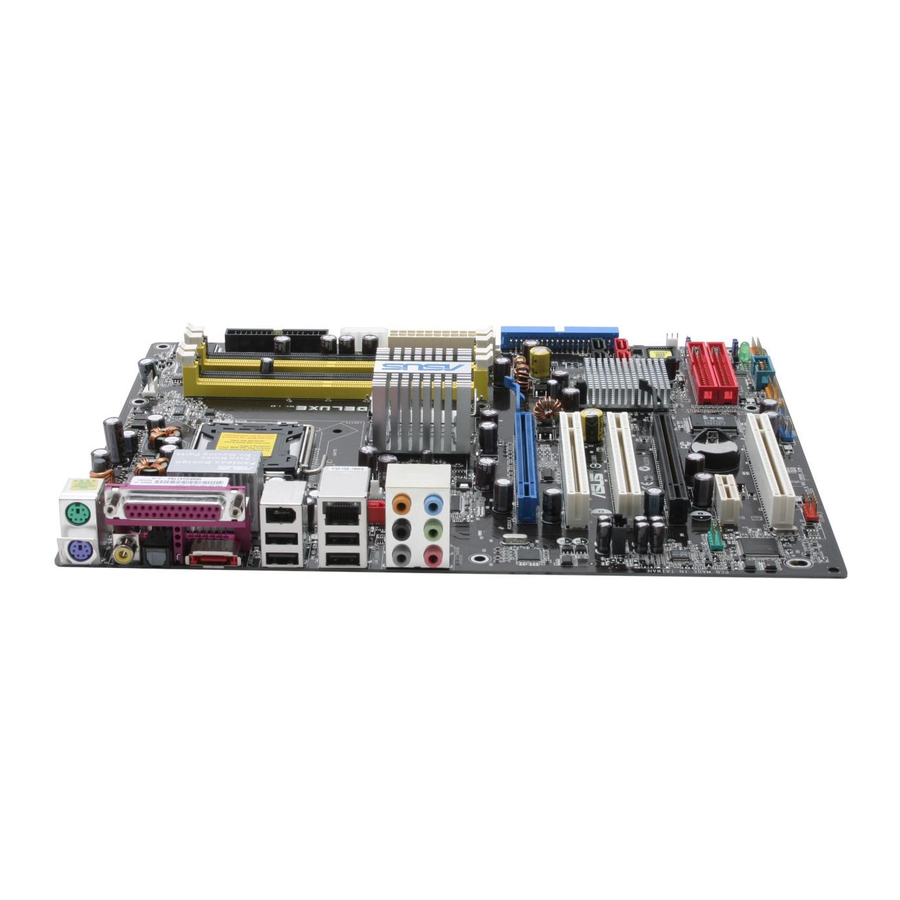
Page 28: Motherboard Layout
2.2.4 2.2.4 2.2.4 2.2.4 2.2.4 Motherboard layout Motherboard layout Motherboard layout Motherboard layout Motherboard layout PS/2KBMS T: Mouse B: Keyboard EATX12V SPDIF_O SPDIF_O2 Bottom: Top: USB1 1394 USB2 CHA_FAN1 USB2.0 Top: T: USB3 LAN port B: USB4 SATA Link SATA_RAID2 AUDIO Marvell 88E8053... -
Page 29: Layout Contents
2.2.5 2.2.5 2.2.5 2.2.5 2.2.5 Layout contents Layout contents Layout contents Layout contents Layout contents S l o t s S l o t s S l o t s S l o t s S l o t s DDR2 DIMM slots PCI Express x16 slot PCI Express U-slot (at PCI Express x4 bandwidth) - Page 30 I n t e r n a l c o n n e c t o r s I n t e r n a l c o n n e c t o r s I n t e r n a l c o n n e c t o r s I n t e r n a l c o n n e c t o r s I n t e r n a l c o n n e c t o r s Floppy disk drive connector (34-1 pin FLOPPY)
-
Page 31: Central Processing Unit (Cpu)
Contact your retailer immediately if the PnP cap is missing, or if you see any damage to the PnP cap/socket pins/motherboard components. ASUS will shoulder the cost of repair only if the damage is shipment/ transit-related. •... - Page 32 Press the load lever with your thumb (A), then move it to the left (B) until it is released from the retention tab. R e t e n t i o n t a b R e t e n t i o n t a b R e t e n t i o n t a b R e t e n t i o n t a b R e t e n t i o n t a b...
- Page 33 The CPU fits in only one correct orientation. DO NOT force the CPU into the socket to prevent bending the connectors on the socket and damaging the CPU! Close the load plate (A), then push the load lever (B) until it snaps into the retention tab.
-
Page 34: Installing The Cpu Heatsink And Fan
2.3.2 2.3.2 2.3.2 2.3.2 2.3.2 Installing the CPU heatsink and fan Installing the CPU heatsink and fan Installing the CPU heatsink and fan Installing the CPU heatsink and fan Installing the CPU heatsink and fan The Intel ® processor in the 775-land package requires a specially designed heatsink and fan assembly to ensure optimum thermal condition and performance. - Page 35 Push down two fasteners at a time in a diagonal sequence to secure the heatsink and fan assembly in place. Connect the CPU fan cable to the connector on the motherboard labeled CPU_FAN. ® P5LD2 DELUXE CPU fan connector Do not forget to connect the CPU fan connector! Hardware monitoring errors can occur if you fail to plug this connector.
-
Page 36: Uninstalling The Cpu Heatsink And Fan
2.3.3 2.3.3 2.3.3 2.3.3 2.3.3 Uninstalling the CPU heatsink and fan Uninstalling the CPU heatsink and fan Uninstalling the CPU heatsink and fan Uninstalling the CPU heatsink and fan Uninstalling the CPU heatsink and fan To uninstall the CPU heatsink and fan: Disconnect the CPU fan cable from the connector on the motherboard. - Page 37 Rotate each fastener clockwise to ensure correct orientation when reinstalling. The narrow end of the groove should point outward after resetting. (The photo shows the groove shaded for emphasis.) Refer to the documentation in the boxed or stand-alone CPU fan package for detailed information on CPU fan installation.
-
Page 38: System Memory
System memory 2.4.1 2.4.1 Overview Overview 2.4.1 2.4.1 2.4.1 Overview Overview Overview The motherboard comes with four Double Data Rate 2 (DDR2) Dual Inline Memory Modules (DIMM) sockets. A DDR2 module has the same physical dimensions as a DDR DIMM but has a 240-pin footprint compared to the 184-pin DDR DIMM. - Page 39 Supports two pairs of modules inserted into the yellow and black slots as two pairs of Dual-channel memory configuration. Visit the ASUS website for the latest DDR2-667 MHz (FSB 1066/800) QVL. A S U S P 5 L D 2 D e l u x e...
- Page 40 C C C C C Supports two pairs of modules inserted into the yellow and black slots as two pairs of Dual-channel memory configuration. Visit the ASUS website for the latest DDR2-533 MHz (FSB 1066/800/ 533) QVL. 2 - 1 6...
-
Page 41: Installing A Dimm
2.4.3 2.4.3 2.4.3 2.4.3 2.4.3 Installing a DIMM Installing a DIMM Installing a DIMM Installing a DIMM Installing a DIMM Unplug the power supply before adding or removing DIMMs or other system components. Failure to do so can cause severe damage to both the motherboard and the components. -
Page 42: Expansion Slots
Expansion slots In the future, you may need to install expansion cards. The following sub-sections describe the slots and the expansion cards that they support. Make sure to unplug the power cord before adding or removing expansion cards. Failure to do so may cause you physical injury and damage motherboard components. -
Page 43: Interrupt Assignments
2.5.3 2.5.3 2.5.3 2.5.3 2.5.3 Interrupt assignments Interrupt assignments Interrupt assignments Interrupt assignments Interrupt assignments Standard interrupt assignments Standard interrupt assignments Standard interrupt assignments Standard interrupt assignments Standard interrupt assignments I R Q I R Q P r i o r i t y P r i o r i t y I R Q I R Q... -
Page 44: Pci Express X16 Slots
2.5.4 2.5.4 2.5.4 2.5.4 2.5.4 PCI Express x16 slots PCI Express x16 slots PCI Express x16 slots PCI Express x16 slots PCI Express x16 slots This motherboard has two PCI Express x16 slots that support PCI Express x16 graphic cards complying with the PCI Express specifications. -
Page 45: Pci Slots
O p t i o n s f o r U n i v e r s a l O p t i o n s f o r U n i v e r s a l O p t i o n s f o r U n i v e r s a l O p t i o n s f o r U n i v e r s a l O p t i o n s f o r U n i v e r s a l P C I E x p r e s s s l o t... -
Page 46: Jumpers
Jumpers 1 . 1 . C l e a r R T C R A M ( C L R T C ) C l e a r R T C R A M ( C L R T C ) C l e a r R T C R A M ( C L R T C ) C l e a r R T C R A M ( C L R T C ) C l e a r R T C R A M ( C L R T C ) -
Page 47: Connectors
Connectors 2.7.1 2.7.1 Rear panel connectors Rear panel connectors 2.7.1 2.7.1 2.7.1 Rear panel connectors Rear panel connectors Rear panel connectors 1 . 1 . P S / 2 m o u s e p o r t ( g r e e n ) . P S / 2 m o u s e p o r t ( g r e e n ) . - Page 48 9 . 9 . M i c r o p h o n e p o r t ( p i n k ) . M i c r o p h o n e p o r t ( p i n k ) . M i c r o p h o n e p o r t ( p i n k ) .
-
Page 49: Internal Connectors
2.7.2 2.7.2 2.7.2 2.7.2 2.7.2 Internal connectors Internal connectors Internal connectors Internal connectors Internal connectors 1 . 1 . F l o p p y d i s k d r i v e c o n n e c t o r ( 3 4 - 1 p i n F L O P P Y ) F l o p p y d i s k d r i v e c o n n e c t o r ( 3 4 - 1 p i n F L O P P Y ) F l o p p y d i s k d r i v e c o n n e c t o r ( 3 4 - 1 p i n F L O P P Y ) F l o p p y d i s k d r i v e c o n n e c t o r ( 3 4 - 1 p i n F L O P P Y ) - Page 50 3 . 3 . I D E c o n n e c t o r s ( 4 0 - 1 p i n P R I _ E I D E [ r e d ] , I D E c o n n e c t o r s ( 4 0 - 1 p i n P R I _ E I D E [ r e d ] , I D E c o n n e c t o r s ( 4 0 - 1 p i n P R I _ E I D E [ r e d ] , I D E c o n n e c t o r s ( 4 0 - 1 p i n P R I _ E I D E [ r e d ] , I D E c o n n e c t o r s ( 4 0 - 1 p i n P R I _ E I D E [ r e d ] ,...
- Page 51 4 . 4 . S e r i a l A T A c o n n e c t o r s ( 7 - p i n S A T A 1 [ r e d ] , S A T A 2 [ r e d ] , S e r i a l A T A c o n n e c t o r s ( 7 - p i n S A T A 1 [ r e d ] , S A T A 2 [ r e d ] , S e r i a l A T A c o n n e c t o r s ( 7 - p i n S A T A 1 [ r e d ] , S A T A 2 [ r e d ] , S e r i a l A T A c o n n e c t o r s ( 7 - p i n S A T A 1 [ r e d ] , S A T A 2 [ r e d ] ,...
- Page 52 5 . 5 . S e r i a l A T A R A I D c o n n e c t o r ( 7 - p i n S A T A _ R A I D 2 ) S e r i a l A T A R A I D c o n n e c t o r ( 7 - p i n S A T A _ R A I D 2 ) S e r i a l A T A R A I D c o n n e c t o r ( 7 - p i n S A T A _ R A I D 2 ) S e r i a l A T A R A I D c o n n e c t o r ( 7 - p i n S A T A _ R A I D 2 )
- Page 53 6 . 6 . O p t i c a l d r i v e a u d i o c o n n e c t o r ( 4 - p i n C D ) O p t i c a l d r i v e a u d i o c o n n e c t o r ( 4 - p i n C D ) O p t i c a l d r i v e a u d i o c o n n e c t o r ( 4 - p i n C D ) O p t i c a l d r i v e a u d i o c o n n e c t o r ( 4 - p i n C D ) O p t i c a l d r i v e a u d i o c o n n e c t o r ( 4 - p i n C D )
- Page 54 8 . 8 . U S B c o n n e c t o r s ( 1 0 - 1 p i n U S B 5 6 , U S B 7 8 ) U S B c o n n e c t o r s ( 1 0 - 1 p i n U S B 5 6 , U S B 7 8 ) U S B c o n n e c t o r s ( 1 0 - 1 p i n U S B 5 6 , U S B 7 8 ) U S B c o n n e c t o r s ( 1 0 - 1 p i n U S B 5 6 , U S B 7 8 ) U S B c o n n e c t o r s ( 1 0 - 1 p i n U S B 5 6 , U S B 7 8 )
- Page 55 P5LD2 DELUXE Fan connectors • Only the CPU_FAN and CHA_FAN1 connectors support the ASUS Q-Fan 2 feature. • If you install two VGA cards, we recommend that you plug the rear chassis fan cable to the motherboard connector labeled CHA_FAN1 for better heat dissipation.
- Page 56 1 4 . 1 4 . 1 4 . C h a s s i s i n t r u s i o n c o n n e c t o r ( 4 - 1 p i n C H A S S I S ) C h a s s i s i n t r u s i o n c o n n e c t o r ( 4 - 1 p i n C H A S S I S ) C h a s s i s i n t r u s i o n c o n n e c t o r ( 4 - 1 p i n C H A S S I S ) C h a s s i s i n t r u s i o n c o n n e c t o r ( 4 - 1 p i n C H A S S I S )
- Page 57 1 6 . 1 6 . ATX power connectors ATX power connectors 1 6 . ATX power connectors 1 6 . 1 6 . ATX power connectors ATX power connectors (24-pin EATXPWR, (24-pin EATXPWR, (24-pin EATXPWR, 8 8 8 8 8 - p i n (24-pin EATXPWR, (24-pin EATXPWR, These connectors are for ATX power supply plugs.
-
Page 58: System Panel Connector
1 7 . 1 7 . 1 7 . S y s t e m p a n e l c o n n e c t o r ( 2 0 - p i n P A N E L ) S y s t e m p a n e l c o n n e c t o r ( 2 0 - p i n P A N E L ) S y s t e m p a n e l c o n n e c t o r ( 2 0 - p i n P A N E L ) S y s t e m p a n e l c o n n e c t o r ( 2 0 - p i n P A N E L ) - Page 59 This chapter describes the power up sequence, the vocal POST messages, and ways of shutting down the system. Powering up...
- Page 60 Chapter summary Starting up for the first time ... 3-1 Powering off the computer ... 3-2 A S U S P 5 L D 2 D e l u x e A S U S P 5 L D 2 D e l u x e A S U S P 5 L D 2 D e l u x e A S U S P 5 L D 2 D e l u x e A S U S P 5 L D 2 D e l u x e...
-
Page 61: Starting Up For The First Time
Starting up for the first time After making all the connections, replace the system case cover. Be sure that all switches are off. Connect the power cord to the power connector at the back of the system chassis. Connect the power cord to a power outlet that is equipped with a surge protector. -
Page 62: Powering Off The Computer
Powering off the computer 3.2.1 3.2.1 Using the OS shut down function Using the OS shut down function 3.2.1 3.2.1 3.2.1 Using the OS shut down function Using the OS shut down function Using the OS shut down function If you are using Windows Click the S t a r t S t a r t S t a r t... -
Page 63: Bios Setup
This chapter tells how to change the system settings through the BIOS Setup menus. Detailed descriptions of the BIOS parameters are also provided. BIOS setup... - Page 64 Chapter summary Managing and updating your BIOS ... 4-1 BIOS setup program ... 4-11 Main menu ... 4-14 Advanced menu ... 4-19 Power menu ... 4-33 Boot menu ... 4-38 Exit menu ... 4-43 A S U S P 5 L D 2 D e l u x e A S U S P 5 L D 2 D e l u x e A S U S P 5 L D 2 D e l u x e A S U S P 5 L D 2 D e l u x e...
-
Page 65: Managing And Updating Your Bios
Refer to the corresponding sections for details on these utilities. Save a copy of the original motherboard BIOS file to a bootable floppy disk in case you need to restore the BIOS in the future. Copy the original motherboard BIOS using the ASUS Update or AFUDOS utilities. 4.1.1 4.1.1... -
Page 66: Afudos Utility
Windows ® 2000 environment To create a set of boot disks for Windows a. Insert a formatted, high density 1.44 MB floppy disk into the drive. b. Insert the Windows c. Click S t a r t S t a r t S t a r t S t a r t S t a r t, then select R u n... - Page 67 Updating the BIOS file To update the BIOS file using the AFUDOS utility: Visit the ASUS website (www.asus.com) and download the latest BIOS file for the motherboard. Save the BIOS file to a bootable floppy disk. Write the BIOS filename on a piece of paper. You need to type the exact BIOS filename at the DOS prompt.
- Page 68 The utility verifies the file and starts updating the BIOS. A:\>afudos /iP5LD2E.ROM AMI Firmware Update Utility - Version 1.19(ASUS V2.07(03.11.24BB)) Copyright (C) 2002 American Megatrends, Inc. All rights reserved. WARNING!! Do not turn off power during flash BIOS Reading file ... done Reading flash ...
-
Page 69: Asus Crashfree Bios 2 Utility
ASUS CrashFree BIOS 2 utility ASUS CrashFree BIOS 2 utility The ASUS CrashFree BIOS 2 is an auto recovery tool that allows you to restore the BIOS file when it fails or gets corrupted during the updating process. You can update a corrupted BIOS file using the motherboard support CD or the floppy disk that contains the updated BIOS file. - Page 70 Restart the system after the utility completes the updating process. The recovered BIOS may not be the latest BIOS version for this motherboard. Visit the ASUS website (www.asus.com) to download the latest BIOS file. 4 - 6...
-
Page 71: Asus Ez Flash Utility
ASUS EZ Flash utility ASUS EZ Flash utility The ASUS EZ Flash feature allows you to update the BIOS without having to go through the long process of booting from a floppy disk and using a DOS-based utility. The EZ Flash utility is built-in the BIOS chip so it is accessible by pressing <Alt>... -
Page 72: Asus Update Utility
ASUS Update utility ASUS Update utility ASUS Update utility ASUS Update utility The ASUS Update is a utility that allows you to manage, save, and update the motherboard BIOS in Windows allows you to: • Save the current BIOS file •... - Page 73 Updating the BIOS through the Internet Updating the BIOS through the Internet To update the BIOS through the Internet: Launch the ASUS Update utility from the Windows S t a r t S t a r t S t a r t > P r o g r a m s...
- Page 74 A S U S U p d a t e A S U S U p d a t e. The ASUS Update main window appears. U p d a t e B I O S f r o m a...
-
Page 75: Bios Setup Program
• Visit the ASUS website (www.asus.com) to download the latest BIOS file for this motherboard. A S U S P 5 L D 2 D e l u x e... -
Page 76: Bios Menu Screen
C o n f i g u r a t i o n f i e l d s [11:10:19] [Thu 03/27/2003] [1.44M, 3.5 in] [English] :[ST320413A] :[ASUS CD-S340] :[Not Detected] :[Not Detected] :[Not Detected] :[Not Detected] C h a p t e r 4 : B I O S s e t u p... -
Page 77: Menu Items
M a i n M a i n M a i n M a i n Primary IDE Master :[ST320413A] Primary IDE Slave :[ASUS CD-S340] Secondary IDE Master :[Not Detected] Secondary IDE Slave :[Not Detected] Third IDE Master :[Not Detected]... -
Page 78: Main Menu
M a i n menu screen appears, [11:51:19] [Thu 05/07/2004] [1.44M, 3.5 in] [English] [ST320413A] [ASUS CD-S520/A] [Not Detected] [Not Detected] [Not Detected] [Not Detected] C h a p t e r 4 : B I O S s e t u p... -
Page 79: Primary, Third And Fourth Ide Master/Slave
4.3.5 4.3.5 4.3.5 4.3.5 4.3.5 Primary, Third and Fourth IDE Master/Slave Primary, Third and Fourth IDE Master/Slave Primary, Third and Fourth IDE Master/Slave Primary, Third and Fourth IDE Master/Slave Primary, Third and Fourth IDE Master/Slave The BIOS automatically detects the connected IDE devices. There is a separate sub-menu for each IDE device. -
Page 80: Ide Configuration
PIO Mode [Auto] PIO Mode [Auto] PIO Mode [Auto] PIO Mode [Auto] PIO Mode [Auto] Selects the PIO mode. Configuration options: [Auto] [0] [1] [2] [3] [4] SMART Monitoring [Auto] SMART Monitoring [Auto] SMART Monitoring [Auto] SMART Monitoring [Auto] SMART Monitoring [Auto] Sets the Smart Monitoring, Analysis, and Reporting Technology. - Page 81 Onboard IDE Operate Mode [Enhanced Mode] Onboard IDE Operate Mode [Enhanced Mode] Onboard IDE Operate Mode [Enhanced Mode] Onboard IDE Operate Mode [Enhanced Mode] Onboard IDE Operate Mode [Enhanced Mode] Disables or allows selection of the IDE operation mode depending on the installed operating system (OS).
-
Page 82: System Information
4.3.7 4.3.7 4.3.7 4.3.7 4.3.7 System Information System Information System Information System Information System Information This menu gives you an overview of the general system specifications. The BIOS automatically detects the items in this menu. AMIBIOS Version : 0118 Build Date : 04/19/05 Processor Type : Genuine Intel(R) CPU 2.80GHz... -
Page 83: Advanced Menu
A I N . O . S . A I N . O . S . A I N . O . S . The ASUS AI Non-delay Overclocking System feature intelligently determines the system load and automatically boost the performance for the most demanding tasks. - Page 84 Performance Mode [Auto] Performance Mode [Auto] Performance Mode [Auto] Performance Mode [Auto] Performance Mode [Auto] Allows enhanced system performance. Setting to [Turbo] may cause the system to become unstable. If this happens, revert to the default setting [Auto]. Configuration options: [Auto] [Standard] [Turbo] The following item appears only when you set the A I O v e r c l o c k i n g item to [Manual].
- Page 85 The following items also appear when the A I O v e r c l o c k i n g to [Manual] or [AI NOS]. Memory Voltage [Auto] Memory Voltage [Auto] Memory Voltage [Auto] Memory Voltage [Auto] Memory Voltage [Auto] Allows you to select the DDR2 reference voltage.
- Page 86 The following item appears only when the A I O v e r c l o c k i n g to [Overclock Profile]. Overclock Options [Overclock 5%] Overclock Options [Overclock 5%] Overclock Options [Overclock 5%] Overclock Options [Overclock 5%] Overclock Options [Overclock 5%] Allows you to overclock the CPU speed through the available preset values.
-
Page 87: Lan Cable Status
4.4.2 4.4.2 4.4.2 4.4.2 4.4.2 LAN Cable Status LAN Cable Status LAN Cable Status LAN Cable Status LAN Cable Status This menu displays the status of the Local Area Network (LAN) cable connected to the LAN (RJ-45) port. POST Check LAN Cable LAN Cable Status Pair Status... -
Page 88: Usb Configuration
4.4.3 4.4.3 4.4.3 4.4.3 4.4.3 USB Configuration USB Configuration USB Configuration USB Configuration USB Configuration The items in this menu allows you to change the USB-related features. Select an item then press <Enter> to display the configuration options. USB Configuration Module Version - 2.24.0-F.4 USB Devices Enabled: None USB Function... -
Page 89: Cpu Configuration
4.4.4 4.4.4 4.4.4 4.4.4 4.4.4 CPU Configuration CPU Configuration CPU Configuration CPU Configuration CPU Configuration The items in this menu show the CPU-related information that the BIOS automatically detects. Configure Advanced CPU settings Manufacturer: Intel Brand String: Genuine Intel(R) CPU 3.20GHz Frequency : 2800 MHz FSB Speed... - Page 90 Max CPUID Value Limit [Disabled] Max CPUID Value Limit [Disabled] Max CPUID Value Limit [Disabled] Max CPUID Value Limit [Disabled] Max CPUID Value Limit [Disabled] Setting this item to [Enabled] allows legacy operating systems to boot even without support for CPUs with extended CPUID functions. Configuration options: [Disabled] [Enabled] Enhanced C1 Control [Auto] Enhanced C1 Control [Auto]...
-
Page 91: Chipset
4.4.5 4.4.5 4.4.5 4.4.5 4.4.5 Chipset Chipset Chipset Chipset Chipset The Chipset menu allows you to change the advanced chipset settings. Select an item then press <Enter> to display the sub-menu. Advanced Chipset Settings Configure DRAM Timing by SPD Hyper Path 3 Boot Graphic Adapter Priority Internal Graphics Mode Select PEG Buffer Length... - Page 92 Hyper Path 3 [Auto] Hyper Path 3 [Auto] Hyper Path 3 [Auto] Allows you to enable or disable the ASUS Hyper Path 3 feature. Configuration options: [Disabled] [Enabled] [Auto] Boot Graphic Adapter Priority [PCI Express/PCI] Boot Graphic Adapter Priority [PCI Express/PCI]...
-
Page 93: Onboard Devices Configuration
4.4.6 4.4.6 4.4.6 4.4.6 4.4.6 Onboard Devices Configuration Onboard Devices Configuration Onboard Devices Configuration Onboard Devices Configuration Onboard Devices Configuration Configure Win627EHF Super IO Chipset HD Audio Controller Front Panel Support Type Onboard 1394 Controller Onboard PCIEX GbE LAN LAN Option ROM Silicon 3132 Controller ITE8212F Controller Detecting Device Time... - Page 94 Silicon 3132 Controller [SATA2 Mode] Silicon 3132 Controller [SATA2 Mode] Silicon 3132 Controller [SATA2 Mode] Silicon 3132 Controller [SATA2 Mode] Silicon 3132 Controller [SATA2 Mode] Allows you to set the onboard Silicon Image SATA RAID controller mode. Configuration options: [SATA2 Mode] [RAID Mode] [Disabled] ITE8211F Controller [Enabled] ITE8211F Controller [Enabled] ITE8211F Controller [Enabled]...
-
Page 95: Pci Pnp
4.4.7 4.4.7 4.4.7 4.4.7 4.4.7 PCI PnP PCI PnP PCI PnP PCI PnP PCI PnP The PCI PnP menu items allow you to change the advanced settings for PCI/PnP devices. The menu includes setting IRQ and DMA channel resources for either PCI/PnP or legacy ISA devices, and setting the memory size block for legacy ISA devices. - Page 96 IRQ-xx assigned to [PCI Device] IRQ-xx assigned to [PCI Device] IRQ-xx assigned to [PCI Device] IRQ-xx assigned to [PCI Device] IRQ-xx assigned to [PCI Device] When set to [PCI Device], the specific IRQ is free for use of PCI/PnP devices. When set to [Reserved], the IRQ is reserved for legacy ISA devices.
-
Page 97: Power Menu
Power menu The Power menu items allow you to change the settings for the ACPI and Advanced Power Management (APM) features. Select an item then press <Enter> to display the configuration options. Suspend Mode Repost Video on S3 Resume ACPI 2.0 Support ACPI APIC Support APM Configuration Hardware Monitor... -
Page 98: Apm Configuration
4.5.5 4.5.5 4.5.5 4.5.5 4.5.5 APM Configuration APM Configuration APM Configuration APM Configuration APM Configuration APM Configuration Power Button Mode Restore on AC Power Loss Power On By RTC Alarm Power On By External Modems Power On By PCI Devices Power On By PCIE Devices Power On By PS/2 Keyboard Power On By PS/2 Mouse... - Page 99 Power On By PCIE Devices [Disabled] Power On By PCIE Devices [Disabled] Power On By PCIE Devices [Disabled] Power On By PCIE Devices [Disabled] Power On By PCIE Devices [Disabled] When set to [Enabled], this parameter allows you to turn on the system through a PCI Express LAN device.
-
Page 100: Hardware Monitor
CPU Q-Fan Control [Disabled] CPU Q-Fan Control [Disabled] CPU Q-Fan Control [Disabled] Allows you to enable or disable the ASUS Q-Fan feature that smartly adjusts the fan speeds for more efficient system operation. Configuration options: [Disabled] [Enabled] The C P U Q - F a n M o d e... - Page 101 Chassis Q-Fan1 Control [Disabled] Chassis Q-Fan1 Control [Disabled] Allows ysou to enable or disable the ASUS Q-Fan feature that smartly adjusts the chassis fan speeds for more efficient system operation. When enabled, the chassis fan ratio is the same with the selected CPU fan ratio.
-
Page 102: Boot Menu
4 - 3 8 Enter Go to Sub-screen [1st FLOPPY DRIVE] [PM-ST330620A] [PS-ASUS CD-S360] [XXXXXXXXX] [XXXXXXXXX] C h a p t e r 4 : B I O S s e t u p C h a p t e r 4 : B I O S s e t u p... -
Page 103: Boot Settings Configuration
Allows you to enable or disable the full screen logo display feature. Configuration options: [Disabled] [Enabled] Set this item to [Enabled] to use the ASUS MyLogo2™ feature. Add On ROM Display Mode [Force BIOS] Add On ROM Display Mode [Force BIOS]... -
Page 104: Security
Interrupt 19 Capture [Disabled] Interrupt 19 Capture [Disabled] Interrupt 19 Capture [Disabled] Interrupt 19 Capture [Disabled] Interrupt 19 Capture [Disabled] When set to [Enabled], this function allows the option ROMs to trap Interrupt 19. Configuration options: [Disabled] [Enabled] 4.6.4 4.6.4 4.6.4 Security Security... - Page 105 After you have set a supervisor password, the other items appear to allow you to change other security settings. Security Settings Supervisor Password : Not Installed User Password : Not Installed Change Supervisor Password User Access Level Change User Password Clear User Password Password Check Boot Sector Virus Protection [Disabled]...
- Page 106 Clear User Password Clear User Password Clear User Password Clear User Password Clear User Password Select this item to clear the user password. Password Check [Setup] Password Check [Setup] Password Check [Setup] Password Check [Setup] Password Check [Setup] When set to [Setup], BIOS checks for user password when accessing the Setup utility.
-
Page 107: Exit Menu
Exit menu The Exit menu items allow you to load the optimal or failsafe default values for the BIOS items, and save or discard your changes to the BIOS items. Exit Options Exit & Save Changes Exit & Discard Changes Discard Changes Load Setup Defaults Pressing <Esc>... - Page 108 Load Setup Defaults Load Setup Defaults Load Setup Defaults Load Setup Defaults Load Setup Defaults Allows you to load the default values for each of the parameters on the Setup menus. When you select this option or if you press <F5>, a confirmation window appears.
-
Page 109: Software Support
This chapter describes the contents of the support CD that comes with the motherboard package. Software support... - Page 110 Chapter summary Installing an operating system ... 5-1 Support CD information ... 5-1 Software information ... 5-9 RAID configurations ... 5-17 Creating a RAID driver disk ... 5-39 A S U S P 5 L D 2 D e l u x e A S U S P 5 L D 2 D e l u x e A S U S P 5 L D 2 D e l u x e A S U S P 5 L D 2 D e l u x e...
-
Page 111: Installing An Operating System
The support CD that came with the motherboard package contains the drivers, software applications, and utilities that you can install to avail all motherboard features. The contents of the support CD are subject to change at any time without notice. Visit the ASUS website(www.asus.com) for updates. 5.2.1 5.2.1 5.2.1... -
Page 112: Drivers Menu
5.2.2 5.2.2 5.2.2 5.2.2 5.2.2 Drivers menu Drivers menu Drivers menu Drivers menu Drivers menu The drivers menu shows the available device drivers if the system detects installed devices. Install the necessary drivers to activate the devices. QFE Update QFE Update QFE Update QFE Update QFE Update... - Page 113 Make ITE8211 32/64 bit IDE Driver Disk Make ITE8211 32/64 bit IDE Driver Disk Make ITE8211 32/64 bit IDE Driver Disk Make ITE8211 32/64 bit IDE Driver Disk Make ITE8211 32/64 bit IDE Driver Disk Allows you to create an ITE8211 IDE driver disk for a 32/64-bit system. Make Silicon Image 32bit RAID Driver Disk Make Silicon Image 32bit RAID Driver Disk Make Silicon Image 32bit RAID Driver Disk...
-
Page 114: Utilities Menu
ASUS Update ASUS Update ASUS Update Allows you to download the latest version of the BIOS from the ASUS website. Before using the ASUS Update, make sure that you have an Internet connection so you can connect to the ASUS website. -
Page 115: Manuals Menu
AI Booster AI Booster AI Booster AI Booster AI Booster Installs the ASUS AI Booster software. Anti-virus application Anti-virus application Anti-virus application Anti-virus application Anti-virus application The anti-virus application detects and protects your computer from viruses that destroys data. 5.2.4 5.2.4... -
Page 116: Asus Contact Information
C o n t a c t C o n t a c t C o n t a c t tab to display the ASUS contact information. You can C o n t a c t also find this information on the inside front cover of this user guide. - Page 117 Technical support Form Technical support Form Technical support Form Displays the ASUS Technical Support Request Form that you have to fill out when requesting technical support. A S U S P 5 L D 2 D e l u x e...
- Page 118 Filelist Filelist Filelist Filelist Filelist Displays the contents of the support CD and a brief description of each in text format. 5 - 8 5 - 8 5 - 8 5 - 8 5 - 8 C h a p t e r 5 : S o f t w a r e s u p p o r t C h a p t e r 5 : S o f t w a r e s u p p o r t C h a p t e r 5 : S o f t w a r e s u p p o r t C h a p t e r 5 : S o f t w a r e s u p p o r t...
-
Page 119: Software Information
ASUS MyLogo2™ ASUS MyLogo2™ ASUS MyLogo2™ The ASUS MyLogo2™ utility lets you customize the boot logo. The boot logo is the image that appears on screen during the Power-On Self-Tests (POST). The ASUS MyLogo2™ is automatically installed when you install the A S U S U p d a t e A S U S U p d a t e utility from the support CD. - Page 120 R a t i o box. R a t i o When the screen returns to the ASUS Update utility, flash the original BIOS to load the new boot logo. 10. After flashing the BIOS, restart the computer to display the new boot logo during POST.
-
Page 121: Ai Net 2
5.3.2 5.3.2 5.3.2 5.3.2 5.3.2 AI NET 2 AI NET 2 AI NET 2 AI NET 2 AI NET 2 The Marvell ® Virtual Cable Tester™ (VCT) is a cable diagnostic utility that reports LAN cable faults and shorts using the Time Domain Reflectometry (TDR) technology. -
Page 122: Audio Configurations
5.3.3 5.3.3 5.3.3 5.3.3 5.3.3 Audio configurations Audio configurations Audio configurations Audio configurations Audio configurations The Realtek ® ALC882M audio CODEC provides 8-channel audio capability to deliver the ultimate audio experience on your PC. The software provides Jack-Sensing function, S/PDIF Out support, and interrupt capability. The ALC882M also includes the Realtek Jack) technology for all audio ports, eliminating cable connection errors and giving users plug and play convenience. - Page 123 Information Information Information Information Information Click the information button ( to display information about the audio driver version, DirectX version, audio controller, audio codec, and language setting. T o o l s T o o l s T o o l s T o o l s T o o l s Click the tool button (...
- Page 124 Sound Effect The Realtek ® ALC882D Audio CODEC allows you to set your listening environment, adjust the equalizer, set the karaoke, or select pre-programmed equalizer settings for your listening pleasure. To set the sound effect options: From the Realtek HD Audio Manager, click the S o u n d E f f e c t E f f e c t...
- Page 125 Bass Management setting Click this tab to manage your bass settings. To set the bass management options: From the Realtek HD Audio Manager, click the B a s s B a s s B a s s B a s s B a s s M a n a g e m e n t s e t t i n g M a n a g e m e n t s e t t i n g tab.
- Page 126 Microphone The Microphone option allows you configure your input/output settings and to check if your audio devices are connected properly. To set the Microphone options: From the Realtek HD Audio Manager, click the M i c r o p h o n e tab.
-
Page 127: Raid Configurations
RAID configurations The motherboard comes with the Silicon Image Sil3132 and the Intel ICH7R Southbridge RAID controllers that allow you to configure IDE and Serial ATA hard disk drives as RAID sets. The motherboard supports the following RAID configurations. R A I D 0 R A I D 0 R A I D 0 (Data striping) optimizes two identical hard disk drives to read and R A I D 0... -
Page 128: Installing Hard Disks
I n t e l I n t e l M a t r i x S t o r a g e M a t r i x S t o r a g e I n t e l I n t e l I n t e l ®... -
Page 129: Intel Raid Configurations
5.5.2 5.5.2 5.5.2 5.5.2 5.5.2 Intel Intel Intel Intel Intel ® ® ® ® ® RAID configurations RAID configurations RAID configurations RAID configurations RAID configurations This motherboard supports RAID 0, RAID 1, RAID 10 (RAID 0+1), RAID 5, and Intel ®... - Page 130 Intel Intel ® ® ® ® ® Matrix Storage Manager Option ROM Utility Matrix Storage Manager Option ROM Utility Intel Intel Intel Matrix Storage Manager Option ROM Utility Matrix Storage Manager Option ROM Utility Matrix Storage Manager Option ROM Utility The Intel ®...
- Page 131 Creating a RAID 0 set (striped) Creating a RAID 0 set (striped) Creating a RAID 0 set (striped) Creating a RAID 0 set (striped) Creating a RAID 0 set (striped) To create a RAID 0 set: From the utility main menu, select 1 . C r e a t e R A I D V o l u m e press <Enter>.
- Page 132 Use the up/down arrow key to select the stripe size for the RAID 0 array, then press <Enter>. The available stripe size values range from 4 KB to 128 KB. The default stripe size is 128 KB. T I P : T I P : T I P : T I P :...
- Page 133 Creating a RAID 1 set (mirrored) Creating a RAID 1 set (mirrored) Creating a RAID 1 set (mirrored) Creating a RAID 1 set (mirrored) Creating a RAID 1 set (mirrored) To create a RAID 1 set: From the utility main menu, select 1 . C r e a t e R A I D V o l u m e press <Enter>.
- Page 134 Creating a RAID 10 set (RAID 0+1) Creating a RAID 10 set (RAID 0+1) Creating a RAID 10 set (RAID 0+1) Creating a RAID 10 set (RAID 0+1) Creating a RAID 10 set (RAID 0+1) To create a RAID 10 set: From the utility main menu, select 1 .
- Page 135 Press <Enter> when the C r e a t e V o l u m e warning message appears. WARNING: ALL DATA ON SELECTED DISKS WILL BE LOST. Are you sure you want to create this volume? (Y/N): Press <Y> to create the RAID volume and return to the main menu or <N>...
- Page 136 The Disks item is highlighted, press <Enter> to select the hard disk drives to configure as RAID. The following pop-up screen appears. Port Drive Model 0 XXXXXXXXXXXX 1 XXXXXXXXXXXX 2 XXXXXXXXXXXX 3 XXXXXXXXXXXX Select 2 to 4 disks to use in creating the volume. ]-Previous/Next Use the up/down arrow key to highlight the drive you want to set, then press <Space>...
- Page 137 Deleting a RAID set Deleting a RAID set Deleting a RAID set Deleting a RAID set Deleting a RAID set Take caution when deleting a RAID set. You will lose all data on the hard disk drives when you delete a RAID set. To delete a RAID set: From the utility main menu, select 2 .
- Page 138 Resetting Disks to Non-RAID Resetting Disks to Non-RAID Resetting Disks to Non-RAID Resetting Disks to Non-RAID Resetting Disks to Non-RAID Take caution before you reset a RAID volume HDD to non-RAID. Resetting a RAID volume HDD deletes all internal RAID structure on the drive. To reset a RAID set hard disk drive: From the utility main menu, select 3 .
-
Page 139: Silicon Image Raid Configurations
5.5.3 5.5.3 5.5.3 5.5.3 5.5.3 Silicon Image RAID configurations Silicon Image RAID configurations Silicon Image RAID configurations Silicon Image RAID configurations Silicon Image RAID configurations The Silicon Image RAID controller supports RAID 0, RAID 1, RAID 10, JBOD, and RAID 5 configurations. Use the Silicon Image RAID utility to configure a disk array. - Page 140 Entering the Silicon Image BIOS RAID Configuration Utility Entering the Silicon Image BIOS RAID Configuration Utility Entering the Silicon Image BIOS RAID Configuration Utility Entering the Silicon Image BIOS RAID Configuration Utility Entering the Silicon Image BIOS RAID Configuration Utility To enter the Silicon Image BIOS RAID configuration utility: Boot up your computer.
-
Page 141: Configuration Utility
Creating a RAID 0 set (Striped) Creating a RAID 0 set (Striped) Creating a RAID 0 set (Striped) Creating a RAID 0 set (Striped) Creating a RAID 0 set (Striped) To create a RAID set: From the Silicon Image configuration utility main menu, select C r e a t e R A I D s e t C r e a t e R A I D s e t... - Page 142 T I P : T I P : T I P : T I P : We recommend a lower stripe size for server systems, and a higher T I P : stripe size for multimedia computer systems used mainly for audio and video editing.
- Page 143 Select your desired method of configuration. A u t o c o n f i g u r a t i o n A u t o c o n f i g u r a t i o n A u t o c o n f i g u r a t i o n A u t o c o n f i g u r a t i o n A u t o c o n f i g u r a t i o n...
- Page 144 e. If you selected C r e a t e w i t h d a t a C r e a t e w i t h d a t a C r e a t e w i t h d a t a C r e a t e w i t h d a t a C r e a t e w i t h d a t a c o p y...
- Page 145 Select your desired method of configuration. A u t o c o n f i g u r a t i o n A u t o c o n f i g u r a t i o n A u t o c o n f i g u r a t i o n A u t o c o n f i g u r a t i o n A u t o c o n f i g u r a t i o n...
- Page 146 Creating a RAID 10 set (Mirrored+Striped) Creating a RAID 10 set (Mirrored+Striped) Creating a RAID 10 set (Mirrored+Striped) Creating a RAID 10 set (Mirrored+Striped) Creating a RAID 10 set (Mirrored+Striped) To create a RAID 10 set: From the Silicon Image configuration utility main menu, select C r e a t e R A I D s e t...
- Page 147 c. The selection bar moves to the Physical Drive menu. Using the up or down arrow keys, select a drive then press <Enter> to set the first drive of the RAID set. d. Repeat step c to set the second, third, and fourth drive. The number of available drives depend on the installed and enabled physical drives in the system.
- Page 148 g. Use the up or down arrow keys to select desired copy method, then press <Enter>. h. The utility prompts a message to input the RAID size, use the up or down arrow keys to set the RAID size then press <Enter>. i.
-
Page 149: Creating A Raid Driver Disk
Creating a RAID driver disk A floppy disk with the RAID driver is required when installing Windows 2000/XP operating system on a hard disk drive that is included in a RAID set. You can create a RAID driver disk in DOS (using the Makedisk application in the support CD) or in Windows To create a RAID driver disk in DOS environment: Place the motherboard support CD in the optical drive. -
Page 150: Disk Drive
The RAID drivers are copied to the floppy disk. After creating a RAID driver disk, eject the floppy disk, then write-protect it to prevent computer virus infection. 10. Press any key to return to the Makedisk menu. To create a RAID driver disk: Place the motherboard support CD into the CD-ROM drive. -
Page 151: Cpu Features
The Appendix describes the CPU features that the motherboard supports. CPU features... -
Page 152: A.1 Intel ® Em64T
Chapter summary Intel ® EM64T ... A-1 Enhanced Intel SpeedStep Intel ® Hyper-Threading Technology ... A-3 A S U S P 5 L D 2 D e l u x e A S U S P 5 L D 2 D e l u x e A S U S P 5 L D 2 D e l u x e A S U S P 5 L D 2 D e l u x e A S U S P 5 L D 2 D e l u x e... -
Page 153: Intel ® Em64T
4 LGA775 processors running on 32-bit operating systems. • The motherboard comes with a BIOS file that supports EM64T. You can download the latest BIOS file from the ASUS website (www.asus.com/support/download/) if you need to update the BIOS file. See Chapter 4 for details. •... -
Page 154: Using The Eist
A.2.2 A.2.2 A.2.2 A.2.2 A.2.2 Using the EIST Using the EIST Using the EIST Using the EIST Using the EIST To use the EIST feature: Turn on the computer, then enter the BIOS Setup. Advanced Menu Advanced Menu Go to the Advanced Menu Advanced Menu Advanced Menu, highlight CPU Configuration then press <Enter>. -
Page 155: Intel ® Hyper-Threading Technology
® Intel Hyper-Threading Technology • The motherboard supports Intel with Hyper-Threading Technology. • Hyper-Threading Technology is supported under Windows Server and Linux 2.4.x (kernel) and later versions only. Under Linux, use the Hyper-Threading compiler to compile the code. If you are using any other operating systems, disable the Hyper-Threading Techonology item in the BIOS to ensure system stability and performance. - Page 156 A - 4 A - 4 A - 4 A - 4 A - 4 A p p e n d i x : C P U f e a t u r e s A p p e n d i x : C P U f e a t u r e s A p p e n d i x : C P U f e a t u r e s A p p e n d i x : C P U f e a t u r e s A p p e n d i x : C P U f e a t u r e s...