Table of Contents
Advertisement
Advertisement
Table of Contents

Related Manuals for Asus P5G41-M LX


Summary of Contents for Asus P5G41-M LX
- Page 1 P5G41-M LX...
- Page 2 Product warranty or service will not be extended if: (1) the product is repaired, modified or altered, unless such repair, modification of alteration is authorized in writing by ASUS; or (2) the serial number of the product is defaced or missing.
-
Page 3: Table Of Contents
Contents Notices ......................v Safety information ..................vi About this guide ..................vii P5G41-M LX specifications summary ............. viii Chapter 1: Product introduction Before you proceed ..............1-1 Motherboard overview ..............1-2 1.2.1 Motherboard layout ............1-2 1.2.2 Layout contents ............... 1-2 Central Processing Unit (CPU) ........... - Page 4 Boot menu .................. 2-13 2.6.1 Boot Device Priority ............2-13 2.6.2 Boot Settings Configuration .......... 2-13 2.6.3 Security ................. 2-14 Tools menu ................. 2-15 2.7.1 ASUS EZ Flash 2 ............2-15 2.7.2 AI NET 2................ 2-15 Exit menu ..................2-15...
-
Page 5: Notices
Complying with the REACH (Registration, Evaluation, Authorisation, and Restriction of Chemicals) regulatory framework, we published the chemical substances in our products at ASUS REACH website at http://green.asus.com/english/REACH.htm. DO NOT throw the motherboard in municipal waste. This product has been designed to enable proper reuse of parts and recycling. -
Page 6: Safety Information
Safety information Electrical safety • To prevent electric shock hazard, disconnect the power cable from the electric outlet before relocating the system. • When adding or removing devices to or from the system, ensure that the power cables for the devices are unplugged before the signal cables are connected. If possible, disconnect all power cables from the existing system before you add a device. -
Page 7: About This Guide
Refer to the following sources for additional information and for product and software updates. ASUS websites The ASUS website provides updated information on ASUS hardware and software products. Refer to the ASUS contact information. Optional documentation Your product package may include optional documentation, such as warranty flyers, that may have been added by your dealer. -
Page 8: P5G41-M Lx Specifications Summary
- 2 x 240-pin DIMM sockets support maximum 8GB unbuffered non-ECC 1066(O.C.)/800/667 MHz DDR2 memory modules Refer to www.asus.com or this user manual for the Memory QVL (Qualified Vendors Lists). ** When you install a total memory of 4GB capacity... - Page 9 P5G41-M LX specifications summary Back panel I/O ports 1 x PS/2 keyboard port 1 x PS/2 mouse port 1 x COM port 1 x VGA port 1 x LAN (RJ-45) port 4 x USB 2.0/1.1 ports 6-channel audio I/O ports Internal I/O connectors 2 x USB 2.0 connectors supports additional 4 USB 2.0 ports...
-
Page 10: Chapter 1: Product Introduction
Chapter 1 Product introduction Thank you for buying an ASUS P5G41-M LX motherboard! ® Before you start installing the motherboard, and hardware devices on it, check the items in your motherboard package. Refer to page ix for the list of accessories. -
Page 11: Motherboard Overview
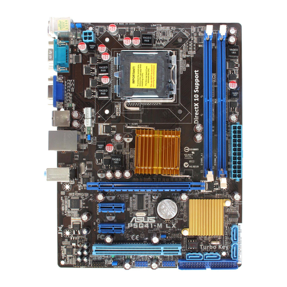
CHA_FAN USBPW1-4 LAN1_USB12 Intel ® AUDIO 8103EL PCIEX16 Super PCIEX1_1 Lithium Cell CMOS Power Intel ® ICH7 P5G41-M LX PCIEX1_2 CLRTC BIOS PCI1 SATA1 SATA3 662-VC1 SB_PWR USB78 USB56 USBPW5-8 PRI_IDE F_PANEL AAFP SPEAKER Place six screws into the holes indicated by circles to secure the motherboard to the chassis. -
Page 12: Central Processing Unit (Cpu)
Contact your retailer immediately if the PnP cap is missing, or if you see any damage to the PnP cap/socket contacts/motherboard components. ASUS will shoulder the cost of repair only if the damage is shipment/transit-related. • Keep the cap after installing the motherboard. ASUS will process Return Merchandise Authorization (RMA) requests only if the motherboard comes with the cap on the LGA775 socket. -
Page 13: Memory Configurations
This motherboard supports up to 8GB on Windows XP Professional x64 and Windows ® ® Vista x64 editions. You may install a maximum of 4GB DIMMs on each slot. P5G41-M LX Motherboard Qualified Vendors Lists (QVL) DDR2-667 MHz capability DIMM support Size Vendor Part No. - Page 14 BL25664AL80A.16FE5(EPP) 4-4-4-12 DS Heat-Sink Package • 4G(2 x 2G) Crucial BL25664AR80A.16FE5(EPP) 4-4-4-12 DS Heat-Sink Package • • 512MB HYMP564U64CP8-S5 AB Hynix SS HY5PS12821CFP-S5 • • HYMP512U64CP8-S5 AB Hynix DS HY5PS12821CFPS5 • • (continued on the next page) ASUS P5G41-M LX...
- Page 15 DDR2-800 MHz capability DIMM support Chip Brand SS/ Size Vendor Part No. Chip No. 512MB Kingmax KLDC28F-A8KI5 Kingmax SS KKA8FF1XF-JFS-25A • • Kingmax GE24GB800C5DC Kingmax DS KKA8FFIXF-HFS-25U • • 512MB Apacer 78.91G91.9K5 Apacer SS AM4B5708JQJS8E0751C • • Apacer 78.01GA0.9K5 Apacer SS AM4B5808CQJS8E0749D •...
- Page 16 • A*: Supports one module inserted into any slot as Single-channel memory configuration. • B*: Supports one pair of modules inserted into both the blue slots as one pair of dual-channel memory configuration. Visit the ASUS website at www.asus.com for the latest QVL. ASUS P5G41-M LX...
-
Page 17: Expansion Slots
Expansion slots In the future, you may need to install expansion cards. The following sub-sections describe the slots and the expansion cards that they support. Unplug the power cord before adding or removing expansion cards. Failure to do so may cause you physical injury and damage motherboard components. -
Page 18: Jumpers
• You do not need to clear the RTC when the system hangs due to overclocking. For system failure due to overclocking, use the CPU Parameter Recall (C.P.R.) feature. Shut down and reboot the system, then the BIOS automatically resets parameter settings to default values. ASUS P5G41-M LX... -
Page 19: Connectors
Set to +5VSB to wake up from S3 and S4 sleep modes (no power to CPU, DRAM in slow refresh, power supply in reduced power mode). USBPW1-4 +5VSB (Default) USBPW5-8 P5G41-M LX +5VSB (Default) P5G41-M LX USB Device Wake Up Connectors 1.7.1 Rear panel connectors 1-10 Chapter 1: Product introduction... - Page 20 Video Graphics Adapter (VGA) port. This 15-pin port is for a VGA monitor or other VGA-compatible devices. COM port. This port is for pointing devices or other serial devices. PS/2 keyboard port (purple). This port is for a PS/2 keyboard. ASUS P5G41-M LX 1-11...
-
Page 21: Internal Connectors
The system may become unstable or may not boot up if the power is inadequate. • If you are uncertain about the minimum power supply requirement for your system, refer to the Recommended Power Supply Wattage Calculator at http://support.asus. com/PowerSupplyCalculator/PSCalculator.aspx?SLanguage=en-us for details. CPU and chassis fan connectors (4-pin CPU_FAN, 3-pin CHA_FAN) The fan connectors support cooling fans of 350 mA~740 mA (8.88 W max.) or a total of... - Page 22 P5G41-M LX NOTE:Orient the red markings on the IDE ribbon cable to PIN 1. P5G41-M LX IDE connector If any device jumper is set as “Cable-Select,” ensure that all other device jumpers have the same setting. Serial ATA connectors (7-pin SATA1-4) These connectors are for the Serial ATA signal cables for Serial ATA 3Gb/s hard disk drives and optical disk drives.
- Page 23 Legacy AC’97 pin definition compliant definition P5G41-M LX Analog front panel connector • We recommend that you connect a high-definition front panel audio module to this connector to avail of the motherboard’s high-definition audio capability. • If you want to connect a high-definition front panel audio module to this connector, set the Front Panel Type item in the BIOS setup to [HD Audio].
-
Page 24: System Panel Connector
PIN 1 P5G41-M LX +HDLED RESET P5G41-M LX System panel connector • System power LED (2-pin PLED) This 2-pin connector is for the system power LED. Connect the chassis power LED cable to this connector. The system power LED lights up when you turn on the system power, and blinks when the system is in sleep mode. -
Page 25: Software Support
The contents of the Support DVD are subject to change at any time without notice. Visit the ASUS website at www.asus.com for updates. To run the Support DVD Place the Support DVD to the optical drive. -
Page 26: Chapter 2: Bios Information
BIOS in the future. Copy the original motherboard BIOS using the ASUS Update utility. 2.1.1 ASUS Update utility The ASUS Update is a utility that allows you to manage, save, and update the motherboard BIOS in Windows environment. ®... -
Page 27: Asus Ez Flash 2
Follow the onscreen instructions to complete the updating process. 2.1.2 ASUS EZ Flash 2 The ASUS EZ Flash 2 feature allows you to update the BIOS without using an OS-based utility. Before you start using this utility, download the latest BIOS file from the ASUS website at www.asus.com. -
Page 28: Asus Crashfree Bios
2.1.3 ASUS CrashFree BIOS The ASUS CrashFree BIOS is an auto recovery tool that allows you to restore the BIOS file when it fails or gets corrupted during the updating process. You can restore a corrupted BIOS file using the motherboard support DVD or a removable device that contains the updated BIOS file. -
Page 29: Main Menu
• The BIOS setup screens shown in this section are for reference purposes only, and may not exactly match what you see on your screen. • Visit the ASUS website at www.asus.com to download the latest BIOS file for this motherboard. -
Page 30: Storage Configuration
Sets Serial ATA, Parallel ATA or both as native mode. Configuration options: [S-ATA] [S-ATA+P-ATA] [P-ATA]. IDE Detect Time Out (Sec) [35] Selects the time out value for detecting ATA/ATAPI devices. Configuration options: [0] [5] [10] [15] [20] [25] [30] [35] ASUS P5G41-M LX... -
Page 31: System Information
2.3.5 System Information This menu gives you an overview of the general system specifications. The BIOS automatically detects the items in this menu. BIOS Information Displays the auto-detected BIOS information. Processor Displays the auto-detected CPU specification. System Memory Displays the auto-detected system memory. Advanced menu The Advanced menu items allow you to change the settings for the CPU and other system devices. - Page 32 VTT Over Voltage [Auto] Allows you to set the VTT over voltage. The values range from 1.10000V to 1.49375V with a 0.00625V increment. Key in the value directly or use +/- to adjust the voltage. Configuration options: [Auto] ASUS P5G41-M LX...
-
Page 33: Cpu Configuration
2.4.2 CPU Configuration The items in this menu show the CPU-related information that the BIOS automatically detects. CPU Ratio Setting [Auto] Sets the ration between CPU core clock and the FSB frequency. Configuration option: [Auto] • If an invalid ratio is set in CMOS then actual and set values may differ. •... -
Page 34: Chipset
Allows you to select the front panel support type. If High Definition Audio Front Panel used, set this item to [HD Audio] mode. Configuration options: [AC97] [HD Audio] 2.4.4 Onboard Devices Configuration Onboard LAN [Enabled] Allows you to enable or disable the onboard LAN controller. Configuration options: [Enabled] [Disabled] ASUS P5G41-M LX... -
Page 35: Usb Configuration
LAN Option ROM [Disabled] Allows you to enable or disable the boot ROM in the onboard LAN controller. This item appears only when the Onboard LAN item is set to Enabled. Configuration options: [Disabled] [Enabled] Serial Port1 Address [3F8/IRQ4] Allows you to select the Serial Port1 base address. Configuration options: [Disabled] [3F8/IRQ4] [2F8/IRQ3] [3E8/IRQ4] [2E8/IRQ3] 2.4.5 USB Configuration... -
Page 36: Pci Pnp
Allows you to enable or disable the Advanced Configuration and Power Interface (ACPI) support in the Application-Specific Integrated Circuit (ASIC). When set to Enabled, the ACPI APIC table pointer is included in the RSDT pointer list. Configuration options: [Disabled] [Enabled] ASUS P5G41-M LX 2-11... -
Page 37: Apm Configuration
2.5.4 APM Configuration Restore on AC Power Loss [Power Off] When set to [Power Off], the system goes into off state after an AC power loss. When set to [Power On], the system goes on after an AC power loss. When set to [Last State], the system goes into either off or on state, whatever the system state was before the AC power loss. -
Page 38: Boot Menu
Configuration options: [Removable Dev.] [Hard Drive] [ATAPI CD-ROM] [Disabled] • To select the boot device during system startup, press <F8> when ASUS Logo appears. • To access Windows OS in Safe Mode, do any of the following: ®... -
Page 39: Security
Hit ‘DEL’ Message Display [Enabled] When set to [Enabled], the system displays the message Press DEL to run Setup during POST. Configuration options: [Disabled] [Enabled] 2.6.3 Security The Security menu items allow you to change the system security settings. Select an item then press <Enter>... -
Page 40: Tools Menu
2.7.1 ASUS EZ Flash 2 Allows you to run ASUS EZ Flash 2. When you press <Enter>, a confirmation message appears. Use the left/right arrow key to select between [Yes] or [No], then press <Enter> to confirm your choice. See section 2.1.2 ASUS EZ Flash 2 for details.