Table of Contents
Advertisement
Advertisement
Table of Contents

Related Manuals for Asus P2B-B


Summary of Contents for Asus P2B-B
- Page 1 P2B-B Pentium II/Celeron Motherboard ® USER’S MANUAL...
- Page 2 Product warranty or service will not be extended if: (1) the product is repaired, modified or altered, unless such repair, modification of alteration is authorized in writing by ASUS; or (2) the serial number of the product is defaced or missing.
-
Page 3: Asus Contact Information
Email: tsd-usa@asus.com.tw WWW: www.asus.com FTP: ftp.asus.com.tw/pub/ASUS ASUS COMPUTER GmbH Marketing Address: Harkort Str. 25, 40880 Ratingen, BRD, Germany Telephone: 49-2102-445011 Fax: 49-2102-442066 Email: info-ger@asus.com.tw Technical Support Hotline: 49-2102-499712 BBS: 49-2102-448690 Email: tsd-ger@asus.com.tw WWW: www.asuscom.de FTP: ftp.asuscom.de/pub/ASUSCOM ASUS P2B-B User’s Manual... -
Page 4: Table Of Contents
I. INTRODUCTION How this Manual is Organized ............7 Item Checklist ..................7 II. FEATURES Features of the ASUS P2B-B Motherboard ........8 The ASUS P2B-B Motherboard ..........11 III. INSTALLATION Layout of the ASUS P2B-B Motherboard ........12 Installation Steps ................14 1. - Page 5 Exit Without Saving ..............57 V. SUPPORT CD ASUS Smart Motherboard Support CD..........58 Desktop Management Interface (DMI) ..........59 Introducing the ASUS DMI Configuration Utility ....59 System Requirements ............59 Using the ASUS DMI Configuration Utility ......60 VI. ASUS LAN Card ASUS PCI-L101 Fast Ethernet Card ..........
-
Page 6: Federal Communications Commission Statement
Canadian Department of Communications Statement This digital apparatus does not exceed the Class B limits for radio noise emissions from digital apparatus set out in the Radio Interference Regulations of the Cana- dian Department of Communications. ASUS P2B-B User’s Manual... -
Page 7: Introduction
(1) Parallel+PS/2 mouse cable on a mounting bracket (1) Bag of spare jumper caps (1) Support CD with drivers and utilities (1) Motherboard User’s manual Infrared module (optional) USB/MIR module (optional) ASUS PCI-L101 Wake-On-LAN 10/100 Ethernet Card (optional) ASUS PC100-compliant SDRAM (optional) ASUS P2B-B User’s Manual... -
Page 8: Features
II. FEATURES Features of the ASUS P2B-B Motherboard The ASUS P2B-B is carefully designed for the demanding PC user who wants ad- vanced features processed by the fastest CPU. Specifications: ® • Multi-Speed: Supports Intel Pentium II (233MHz to 450MHz) and Celeron (266MHz and faster) processors. - Page 9 • PC’98 Compliant: Both the BIOS and hardware levels of ASUS smart series of motherboards meet PC’98 compliancy. The new PC’98 requirements for sys- tems and components are based on the following high-level goals: Support for...
- Page 10 Voltage Monitoring and Alert: System voltage levels are monitored to ensure stable voltage to critical motherboard components. Voltage specifications are more critical for future processors, so monitoring is necessary to ensure proper system configuration and management. ASUS P2B-B User’s Manual...
-
Page 11: The Asus P2B-B Motherboard
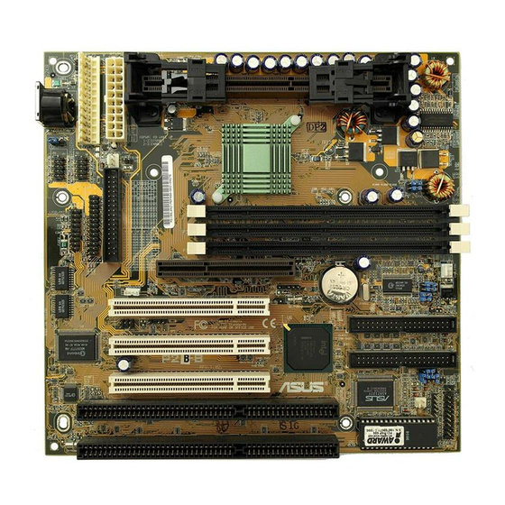
II. FEATURES The ASUS P2B-B Motherboard Thermal PS/2 Mouse, USB, AT Power Sensor Connector IrDA Header Serial, Parallel, Floppy Connector Super Multi-I/O Hardware Monitor 2 ISA Slots 3 PCI Slots ATX Power Connector AGP Slot Slot 1 Intel 440BX AGPset... -
Page 12: Installation
III. INSTALLATION Layout of the ASUS P2B-B Motherboard KB-PS2KB Hardware COM 1 Monitor USB/MIR Super KBPWR Serial Ports Keyboard Multi PARALLEL COM 2 AT Power Connector PWR_FAN ATXPWR ATX Power Connector FLOPPY WOL_CON Wake-On-LAN SBLINK Connector CPU_FAN Intel 440BX AGPset... -
Page 13: Hardware Monitor
33 SMBus Connector (3 pins) 22) CHASIS p. 34 Chassis Intrusion Alarm Lead (3 pins) The onboard hardware monitor uses the address 290H-297H so legacy ISA cards must not use this address or else conflicts will occur. ASUS P2B-B User’s Manual... -
Page 14: Installation Steps
RTC data: (1) Unplug your computer, (2) Short solder points, (3) Turn on your computer, (4) Hold down <Delete> during bootup and enter BIOS setup to re- enter user preferences. RTC RAMCLRTC Clear Data [short solder points momentarily] CLRTC P2B-B Clear RTC RAM ASUS P2B-B User’s Manual... - Page 15 Enable [2-3] KBPWR KBPWR Disable Enable (Default) P2B-B Keyboard Power Up 3. Voltage Input/Output Selection (VIO) This jumper allows you to select the voltage supplied to the DRAM, chipset, AGP, and the CPU’s I/O buffer. Setting 3.50V [2-3] (default) 3.66V...
- Page 16 Overclocking your processor is not recommended. It may result in a slower speed. Voltage Regulator Output Selection (VID) is not needed for the Pentium II/Celeron processor because it sends a VID signal directly to the onboard power controller. ASUS P2B-B User’s Manual...
-
Page 17: System Memory (Dimm)
BIOS shows SDRAM memory on bootup screen. • 8 chips/side modules do not support ECC, only 9 chips/side modules support ECC. • Single-sided DIMMs come in 16, 32, 64,128MB; double-sided come in 32, 64, 128, 256MB. ASUS P2B-B User’s Manual... -
Page 18: Dimm Memory Installation Procedures
20 Pins 60 Pins 88 Pins Lock P2B-B 168-Pin DIMM Memory Sockets The DIMMs must be 3.3Volt unbuffered SDRAMs. To determine the DIMM type, check the notches on the DIMMs (see figure below). 168-Pin DIMM Notch Key Definitions (3.3V) Voltage Key Position... -
Page 19: Central Processing Unit (Cpu)
Be sure that there is sufficient air circulation across the processor’s heatsink by regularly checking that your CPU fan is working. Without sufficient circulation, the processor could overheat and damage both the processor and the motherboard. You may install an auxiliary fan, if necessary. ASUS P2B-B User’s Manual... -
Page 20: Installing The Processor
SECC2/SEPP, with one pair of the heatsink clip legs going first through the corresponding heatsink holes, and then the other pair. (NOTE: The heatsink and SECC2/SEPP holes are slightly offset to ensure good locking grip between the two.) ASUS P2B-B User’s Manual... - Page 21 5. Attach the Thermal Sensor Cable (optional): If you purchased an ASUS Smart Fan (ASUS S-P2FAN) with an integrated thermal sensor cable (ASUS P2T-Cable) or purchased separately the P2T-Cable, you can connect the thermal sensor cable to your motherboard’s thermal sensor connector.
-
Page 22: Asus Smart Thermal Solutions
ASUS S-P2FAN has an integrated thermal sensor located near the center of the CPU heat source. The sensor is optimized by ASUS to give the most accurate reading of the CPU tempera- ture, thus provides the best protection to your computer system. -
Page 23: Recommended Heatsinks For Slot 1 Processors
The recommended heatsinks for the Slot 1 processors are those with three-pin fans, such as the ASUS Smart Fan, that can be connected to the motherboard’s CPU fan connector. These heatsinks, such as the Elan Vital Heatsink with Fan, dissipate heat more efficiently and with an optional hardware monitor, they can monitor the fan’s... -
Page 24: Expansion Cards
(to gain access, double-click the System icon under the Control Panel program). Ensure that no two devices share the same IRQs or your computer will experience problems when those two devices are in use at the same time. ASUS P2B-B User’s Manual... -
Page 25: Assigning Dma Channels For Isa Cards
Accelerated Graphics Port This motherboard provides an accelerated graphics port (AGP) slot to support a new generation of graphics cards with ultra-high memory bandwidth, such as an ASUS 3D hardware accelerator. P2B-B Accelerated Graphics Port (AGP) -
Page 26: External Connectors
WARNING! Some pins are used for connectors or power sources. These are clearly separated from jumpers in “Map of the ASUS Motherboard.” Placing jumper caps over these will cause damage to your motherboard. IMPORTANT: Ribbon cables should always be connected with the red stripe on the Pin 1 side of the connector. - Page 27 IRQ through the Onboard Serial Port in Chipset Features of the BIOS SOFT- WARE. (Pin 10 is removed to prevent inserting in the wrong orientation when using ribbon cables with pin 10 plugged). COM 1 Pin 1 COM 2 Pin 1 P2B-B Serial Port Connectors ASUS P2B-B User’s Manual...
- Page 28 Primary or Secondary IDE connectors will cause the LED to light up. TIP: If the case-mounted LED does not light, try reversing the 2-pin plug. IDELED P2B-B IDE Activity LED ASUS P2B-B User’s Manual...
- Page 29 8. Wake-On-LAN Connector (3-pin WOL_CON) This connector connects to a LAN card with a Wake-On-LAN output, such as the ASUS PCI-L101. The LAN card powers up the system when a wakeup packet or signal is received from the network. IMPORTANT: This feature requires that the WAKE On LAN Power Up Con- trol is set to Enabled (see “Power Management Setup”...
- Page 30 15. Speaker Connector (4-pin SPEAKER) This 4-pin connector connects to the case-mounted speaker. Keyboard Lock Speaker Connector Power LED Reset SW Message LED ATX Power SMI Lead Switch* Requires an ATX power supply. P2B-B System Panel Connections ASUS P2B-B User’s Manual...
- Page 31 9: +5 Volt 18: Infrared Transmit Optional USB/MIR P2B-B PS/2 Mouse, USB, IrDA Module Connector 17. IrDA-Compliant infrared module connector (5-pin IR) This connector supports the optional wireless transmitting and receiving infrared module. This module mounts to a small opening on system cases that support this feature.
- Page 32 For Wake-On-LAN support, your ATX power supply must supply at least 720mAmp. P2B-B ATX Power Connector 19. AT Power Supply Connector (12-pin PS/2) This connector connects to a standard 5 Volt power supply. To connect the leads from the power supply, ensure first that the power supply is not plugged.
- Page 33 C bus, which is a multi-master bus, that is, multiple chips can be connected to the same bus and each one can act as a master by initiating data transfer. SMBCLK Ground SMBDATA P2B-B SMBus Connector ASUS P2B-B User’s Manual...
- Page 34 “chassis signal” lead. This occurs when a panel switch or light detector is triggered. This function requires optional trig- ger switches to be installed. +5Volt (Power Supply Stand By) Chassis Signal Ground P2B-B Chassis Open Alarm Lead ASUS P2B-B User’s Manual...
-
Page 35: Power Connection Procedures
If you use Windows 95, click the Start button, click Shut Down, and then click Shut down the computer? NOTE: The message “You can now safely turn off your computer” will not appear when shutting down with ATX power supplies. ASUS P2B-B User’s Manual... -
Page 36: Bios Software
To save your current BIOS, type [1] at the Main Menu and then press <Enter>. The Save Current BIOS To File screen appears. Type a filename and the path, for example, A:\XXX-X and then press <Enter>. ASUS P2B-B User’s Manual... - Page 37 BIOS update, press Y to start the update. The utility starts to program the new BIOS information into the flash ROM. When the program- ming is finished, Flashed Suc- cessfully will be displayed. Follow the onscreen instructions to continue. ASUS P2B-B User’s Manual...
-
Page 38: Managing And Updating Your Motherboard's Bios
Updating BIOS Procedures (only when necessary) 1. Download an updated ASUS BIOS file from the Internet (WWW or FTP) or a BBS (Bulletin Board Service) (see ASUS CONTACT INFORMATION on page 3 for details) and save to the disk you created earlier. -
Page 39: Bios Setup
Reset button on the system case. You can also restart by turning the system off and then back on again. But do so only if the first two methods fail. When you invoke Setup, the CMOS SETUP UTILITY main program screen will appear with the following options: ASUS P2B-B User’s Manual... -
Page 40: Load Defaults
To set the date, highlight the “Date” field and then press either <Page Up>/<Page Down> or <+>/<–> to set the current date. Follow the month, day and year format. Valid values for month, day and year are: Month: (1 to 12), Day: (1 to 31), Year: (up to 2079) ASUS P2B-B User’s Manual... - Page 41 IDE hard disks; set it to Large for drives over 528MB that do not sup- port LBA. Large type of drive can only be used with MS-DOS and is very uncom- mon. Most IDE drives over 528MB support the LBA mode. ASUS P2B-B User’s Manual...
- Page 42 If you are using a VGA or any higher resolution card, choose EGA/VGA. Halt On (All Errors) This field determines which types of errors will cause the system to halt. Choose from All Errors; No Errors; All, But Keyboard, All, But Diskette; and All, But Disk/Key. ASUS P2B-B User’s Manual...
-
Page 43: Bios Features Setup
Be- cause of conflicts with new operating systems, for example, during installation of new softwares, you may have to set this to Disabled to prevent write errors. ASUS P2B-B User’s Manual... - Page 44 This field enhances hard disk performance by making multi-sector transfers instead of one sector per transfer. Most IDE drives, except older versions, can utilize this feature. Selections are HDD MAX, Disabled, 2, 4, 8, 16, and 32. ASUS P2B-B User’s Manual...
- Page 45 The default setting is System, where the system prompts for the User Password every time you start your system. The other option is Setup, where the system goes through its startup routine unless the Setup utility is called, when the system prompts for the Supervisor Password. ASUS P2B-B User’s Manual...
-
Page 46: Chipset Features Setup
Enabled will allow PCI streaming. Leave on default setting. Host Bus Fast Data Ready (Disabled) Leave on default setting. 16-bit I/O Recovery Time (1 BUSCLK) / 8-bit I/O Recovery Time (1 BUSCLK) Timing for 16-bit and 8-bit ISA cards, respectively. Leave on default setting. ASUS P2B-B User’s Manual... - Page 47 When Enabled, this field allows you to connect your floppy disk drives to the onboard floppy disk drive connector instead of a separate controller card. If you want to use a different controller card to connect the floppy disk drives, set this field to Disabled. ASUS P2B-B User’s Manual...
- Page 48 Because each IDE device may have a different Mode timing (0, 1, 2, 3, 4), it is necessary for these to be independent. The default setting of Auto will allow autodetection to ensure optimal performance ASUS P2B-B User’s Manual...
-
Page 49: Power Management Setup
Power Management Field. Video Off Option (Suspend -> Off ) This field determines when to activate the video off feature for monitor power manage- ment. The settings are Suspend -> Off and Always On. ASUS P2B-B User’s Manual... - Page 50 4 seconds. Suspend allows the button to have a dual function where pressing less than 4 seconds will place the system in sleep mode. Regardless of the setting, holding the ATX switch for more than 4 seconds will power off the system. ASUS P2B-B User’s Manual...
- Page 51 With this feature, you can remotely upload/download data to/from systems during off-peak hours. Set to Enabled to set this feature. IMPORTANT: This feature requires the ASUS PCI-L101 LAN Card and an ATX power supply with at least 720mA +5V standby power.
-
Page 52: Pnp And Pci Setup
ICU, you must set the field for that IRQ to Yes. For example: If you install a legacy ISA card that requires IRQ 10, then set IRQ10 Used By ISA to Yes............................ASUS P2B-B User’s Manual... - Page 53 If your computer has both PCI and AGP VGA cards, this field allows you to select which of the cards will act as your primary card. The default, PCI/AGP, allows your PCI card to take precedent when detected. AGP/PCI uses the AGP card as your primary card. ASUS P2B-B User’s Manual...
-
Page 54: Load Bios Defaults
<Enter>. The system displays a confirmation message on the screen. Press <Y> and then <Enter> to confirm. Press <N> and then <Enter> to abort. This feature does not affect the fields on the Standard CMOS Setup screen. ASUS P2B-B User’s Manual... -
Page 55: Supervisor Password And User Password
<Enter> instead of entering a new password when the “Enter Password” prompt appears. A message confirms the password has been disabled. NOTE: If you forget the password, see CMOS RAM for procedures on clearing the CMOS. ASUS P2B-B User’s Manual... -
Page 56: Ide Hdd Auto Detection
The auto-detection feature can only detect one set of parameters for a particular IDE hard drive. Some IDE drives can use more than one set. This is not a problem if the drive is new and empty. ASUS P2B-B User’s Manual... -
Page 57: Save & Exit Setup
Select this option to exit the Setup utility without saving the modifications you specify during the current session. To exit without saving, highlight the “Exit Without Sav- ing” option on the main screen and then press <Enter>. ASUS P2B-B User’s Manual... -
Page 58: Support Cd
Patch for PIIX4 chipset: Installs the necessary drivers for PCI card and PCI bridge for Windows 95/95a (OSR1) and 95b (OSR2) for ASUS motherboards. • Browse this CD: Allows you to see the contents of the ASUS support CD. • Technical Support Form: View the Technical Support Form with Notepad. -
Page 59: Desktop Management Interface (Dmi)
V. SUPPORT CD Desktop Management Interface (DMI) Introducing the ASUS DMI Configuration Utility This motherboard supports DMI within the BIOS level and provides a DMI Con- figuration Utility to maintain the Management Information Format Database (MIFD). DMI is able to auto-detect and record information pertinent to a computer’s system such as the CPU type, CPU speed, and internal/external frequencies, and memory size. -
Page 60: Using The Asus Dmi Configuration Utility
V. SUPPORT CD Using the ASUS DMI Configuration Utility NOTE: The following screen displays are provided as examples only and may not reflect the screen contents on your system. Edit DMI (or delete) Use the (left-right) cursors to move the top menu items and the (up-down) cursor to move between the left hand menu items. - Page 61 You can load the BIOS defaults from a MIFD file and can clear all user modified and added data. You must reboot your computer in order for the defaults to be saved back into the Flash BIOS. ASUS P2B-B User’s Manual...
- Page 62 V. SUPPORT CD (This page was intentionally left blank) ASUS P2B-B User’s Manual...
-
Page 63: Asus Lan Card
Motherboard type Other If you are using the ASUS PCI-L101 on an ASUS motherboard, leave the jumper on its default setting of “ASUS.” If you are using another brand of motherboard, set the jumper to “Other.” Connect the Wake-On-LAN (WOL) output signal to the motherboard’s WOL_CON in order to utilize the Wake-On-LAN feature of the moth-... -
Page 64: Features
A: To enable Wake-On-LAN function, your system requires Ethernet LAN adapter card that can activate Wake-On-LAN function, a client with Wake-On-LAN capa- bility, and software such as LDCM Rev. 3.10 or up that can trigger wake-up frame. ASUS P2B-B User’s Manual...