Advertisement
Quick Links
Advertisement

Related Manuals for Electro-Voice CPS 3


Summary of Contents for Electro-Voice CPS 3
- Page 1 OWNER’S MANUAL CPS 3 / CPS 4 CONTRACTOR PRECISION SERIES...
-
Page 2: Important Safety Instructions
IMPORTANT SAFETY INSTRUCTIONS Read these instructions. Keep these instructions. Heed all warnings. Follow all instructions. Do not use this apparatus near water. Clean only with a damp cloth. Do not block any of the ventilation openings. Install in accordance with the manufactures instructions. Do not install near any heat sources such as radiators, heat registers, stoves, or other apparatus that produce heat. -
Page 3: Table Of Contents
First of all, we would like to express our thanks and at the same time congratulate you on the decision to buy one of our CONTRACTOR PRECISION SERIES power amplifiers. Electro-Voice CONTRACTOR PRECISION SERIES amplifiers are made to meet the highest require- ments of any on-the-road application. Thus they provide on-board protection against thermal and capacitive overload, short-circuit and the occurrence of HF or DC at the output. -
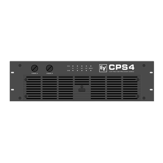
Page 4: Front Panel
FRONT PANEL 1. Level Control To prevent unauthorized operation of the level controls on the CPS3 and CPS4, they are provided with screwed-on protective cover lids. When shipped from the factory, the detented potentiometers are set to their clockwise limits. Thus, the input signal is not attenuated. In case matching the input levels is required, you first have to detach (unscrew) the cover lids to gain access to the potentiometers. -
Page 5: Rear Panel
POWER AMPLIFIER INPUTS Parallel to the XLR-type inputs, output connectors are provided, offering the opportunity to feed additional power amplifiers with the same signal. The inputs are electrically balanced with pin-assignment according to the IEC 268 standard. Pin-assignment of the XLR-type input connectors: PIN 1: SHIELD PIN 2:... - Page 6 REAR PANEL POWER AMPLIFIER OUTPUT CONNECTORS SPEAKON output connectors are provided for the power amplifier channels A (left) and B (right). The Bridged Out Connector for bridged operation is sealed with a plastic cover to prevent connection errors. LIMITER The time constant of the built-in limiter to avoid overdri- ving is adjustable.
-
Page 7: Specifications
Technical Specifications: CPS3, CPS4 Amplifier at rated conditions, both channels driven with 8 ohms loads, unless otherwise specified. Load Impedance Maximum Midband Output Power THD=1%, 1kHz Rated Output Power THD< 0.1%, 20Hz ... 20kHz Maximum Bridged Output Power THD=1%, 1kHz Maximum RMS Voltage Swing THD=1%, 1kHz Voltage Gain... -
Page 8: Block Diagram
BLOCK DIAGRAM... -
Page 9: Dimensions
ABMESSUNGEN/DIMENSIONS Abmessungen/Dimensions (in mm)