Yamaha YSP 900 - Digital Sound Projector Five CH Speaker Owner's Manual
Digital sound projector
Hide thumbs
Also See for YSP 900 - Digital Sound Projector Five CH Speaker:
- Owner's manual (362 pages) ,
- Service manual (82 pages) ,
- Owner's manual (94 pages)
Table of Contents
Advertisement
Quick Links
Advertisement
Table of Contents

Related Manuals for Yamaha YSP 900 - Digital Sound Projector Five CH Speaker


Summary of Contents for Yamaha YSP 900 - Digital Sound Projector Five CH Speaker
- Page 1 YSP-900 Digital Sound Projector OWNER’S MANUAL...
-
Page 2: Important Safety Instructions
IMPORTANT SAFETY INSTRUCTIONS IMPORTANT SAFETY INSTRUCTIONS Read these instructions. Keep these instructions. CAUTION Heed all warnings. RISK OF ELECTRIC SHOCK Follow all instructions. DO NOT OPEN Do not use this apparatus near water. CAUTION: TO REDUCE THE RISK OF Clean only with dry cloth. ELECTRIC SHOCK, DO NOT REMOVE Do not block any ventilation openings. - Page 3 – and, most importantly, without affecting your sensitive hearing. Since hearing damage from loud sounds is often undetectable until it is too late, YAMAHA and the Electronic Industries Association’s Consumer Electronics Group recommend you to avoid prolonged exposure from excessive volume levels.
- Page 4 YAMAHA will IMPORTANT not be held responsible for any damage resulting from use of this unit with a voltage other than specified.
-
Page 5: Table Of Contents
CONTENTS Enjoying 2-channel sources INTRODUCTION in surround sound ..........43 Enjoying TV in surround sound ......44 OVERVIEW ............2 Adjusting surround mode parameters...... 45 FEATURES............. 3 ENJOYING STEREO SOUND ......46 USING THIS MANUAL ........4 Stereo playback............46 SUPPLIED ACCESSORIES ......... 5 PLAYING BACK SOUND CLEARLY CONTROLS AND FUNCTIONS ...... -
Page 6: Overview
YAMAHA YSP-900 Digital Sound Projector challenges this preconception that complicated speaker setup and troublesome wiring go hand-in-hand with the enjoyment of multi-channel surround sound. -
Page 7: Features
This unit employs the Cinema DSP Digital technology Dolby Pro Logic developed by YAMAHA Electronics Corp. so that you can This sophisticated, matrix decoding technology up-converts experience movies at home with all the dramatic sound any 2 channel source audio to a 5.1 channel full bandwidth... -
Page 8: Using This Manual
USING THIS MANUAL USING THIS MANUAL Notes • This manual describes how to connect and operate this unit. For details regarding the operation of external components, refer to the supplied owner’s manual for the component. • Some operations can be performed by using either the buttons on the main unit or on the remote control. In such cases, the operation is described using remote control operation. -
Page 9: Supplied Accessories
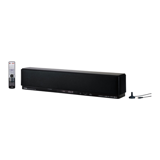
SUPPLIED ACCESSORIES SUPPLIED ACCESSORIES Check that you have received all of the following parts. Remote control (×1) Batteries (×2) Optical cable (×1) (AA, R6, UM-3) STANDBY/ON POWER POWER INPUT1 INPUT2 MACRO AUTO OSD video pin cable (×1) Digital audio pin cable (×1) VOL MODE SETUP INPUTMODE SLEEP... -
Page 10: Controls And Functions
CONTROLS AND FUNCTIONS CONTROLS AND FUNCTIONS Front panel INPUT VOLUME STANDBY/ON 1 OPTIMIZER MIC jack 6 STANDBY/ON Use to connect the supplied optimizer microphone to be Turns on the power of this unit or sets it to the standby used to run AUTO SETUP (see page 28). mode (see page 23). -
Page 11: Front Panel Display
CONTROLS AND FUNCTIONS Front panel display NIGHT SLEEP DIGITAL 1 NIGHT indicator 4 Volume level indicator Lights up when one of the night listening modes is Shows the current volume level (see page 39). selected (see page 52). 5 Multi-information display 2 SLEEP indicator Shows information when you adjust the parameters of this Lights up when the sleep timer is turned on (see page 55). -
Page 12: Rear Panel
CONTROLS AND FUNCTIONS Rear panel (Europe model) TV/STB SUBWOOFER VIDEO TV/STB OPTICAL COAXIAL AUDIO INPUT DIGITAL INPUT 1 VCR analog audio input jacks 6 AUX OPTICAL DIGITAL INPUT jack Use to make an analog connection to your VCR Use to connect an external component via an optical (see page 17). -
Page 13: Remote Control
CONTROLS AND FUNCTIONS Remote control 1 Infrared window The functions of some buttons change depending on the position of the operation mode selector (S). This section Outputs infrared control signals. Aim this window at the basically describes the functions of the remote control component you want to operate. - Page 14 CONTROLS AND FUNCTIONS H TV POWER Turns on the power of the TV or sets it to the standby mode (see page 78). I AV POWER Turns on the power of the selected component or sets it to the standby mode (see pages 78 and 79). J INPUT1/INPUT2 Selects the input source of the TV (see page 78).
-
Page 15: Installation
INSTALLATION INSTALLATION This section describes a suitable installation location to install the unit using a metal wall bracket, a rack or a stand. Before installing this unit Installing this unit This unit creates surround sound by reflecting projected Install this unit where there are no obstacles such as sound beams off the walls of your listening room. -
Page 16: Installation Examples
INSTALLATION Installation examples Example 1 Install this unit as close to the exact center of the wall as possible. Example 2 Install this unit so that the sound beams can be reflected off the walls. Example 3 Install this unit as close to the exact front of your normal listening position. - Page 17 INSTALLATION Using a metal wall bracket Using a rack You can use the optional metal wall bracket to mount this You can install this unit either above or under your TV in a unit on the wall in your listening room. commercially available rack.
-
Page 18: Connections
CONNECTIONS CONNECTIONS This unit is equipped with two optical digital jacks, one coaxial digital jack and two types of analog jacks for connecting external components such as your TV, DVD player, VCR, digital satellite tuner, cable TV tuner and game console. Further, by connecting a subwoofer to this unit, you can enjoy reinforced low bass sounds. -
Page 19: Connecting A Tv
CONNECTIONS Connecting a TV You can connect a TV to this unit and display the OSD for easy viewing when you adjust the system parameters in SET MENU. To prevent the optical cable from being unplugged, affix the optical cable in the supplied cable clamp (see page 14). Note If you connect this unit to the analog audio and optical digital audio output jacks at the same time as shown in the left illustration below, the digital audio signals output at the optical digital output jack take priority over the analog audio signals output at the analog audio... -
Page 20: Connecting A Dvd Player/Recorder
CONNECTIONS Connecting a DVD player/recorder To connect a DVD player/recorder, connect the coaxial digital output jack on your DVD player to the coaxial digital input jack (DVD COAXIAL) on this unit. If there is no coaxial digital output jack on your DVD player/recorder, use them with optical digital connection. To prevent the optical cable from being unplugged, affix the optical cable in the supplied cable clamp (see page 14). -
Page 21: Connecting A Vcr
CONNECTIONS Connecting a VCR To connect a VCR, connect the analog audio output jacks on your VCR to the analog audio input jacks (VCR R/L) on this unit. Connect red plugs to the right jacks and white plugs to the left jacks. Video signal to a TV Analog audio output... -
Page 22: Connecting A Digital Satellite Tuner Or A Cable Tv Tuner
CONNECTIONS Connecting a digital satellite tuner or a cable TV tuner To connect a digital satellite tuner or a cable TV tuner, connect the optical digital output jack on your digital satellite tuner or cable TV tuner to the optical digital input jack (TV/STB OPTICAL) on this unit. In addition, connect the analog audio output jacks on your VCR to the analog audio input jacks (TV/STB R/L) on this unit. -
Page 23: Connecting Other External Components
CONNECTIONS Connecting other external components To connect other external components, connect the optical digital output jack on the component to the optical digital input jack (AUX OPTICAL) on this unit. You can connect a DVD player/recorder or a component that supports optical digital connections. To prevent the optical cable from being unplugged, affix the optical cable in the supplied cable clamp (see page 14). -
Page 24: Connecting A Subwoofer
CONNECTIONS Connecting a subwoofer To connect a subwoofer, connect the monaural input jack on your subwoofer to the monaural audio output jack (SUBWOOFER OUT) on this unit. No sound will be output from a subwoofer when only this connection has been made. To output sounds from a subwoofer, turn on the power of your subwoofer and then run AUTO SETUP (see page 27) or select SWFR for BASS OUT in SUBWOOFER SET (see page 63). -
Page 25: Connecting The Power Supply Cable
CONNECTIONS Connecting the power supply cable Once all other connections are complete, plug the power supply cable into the AC wall outlet. To the AC outlet... -
Page 26: Getting Started
GETTING STARTED GETTING STARTED Installing batteries in the remote Remove the transparent sheet before using the remote control. control Press Operation range of the remote control You can control other components by setting the appropriate The remote control transmits a directional infrared beam. Use the remote control within 6 m (20 ft) of this unit and Press and hold the mark on the battery... -
Page 27: Using The Remote Control
GETTING STARTED Using the remote control Turning on the power This section describes how to control this unit using the supplied remote control. The functions of the remote control change depending on the position of the operation mode selector. Set the operation mode selector to YSP to switch to the operation mode of this unit. -
Page 28: Using Set Menu
USING SET MENU USING SET MENU Displaying the OSD This section simply describes how to display the OSD (on-screen display) of this unit on your TV screen and set the parameters for your listening room. Once this is complete, you can enjoy real surround sound while watching TV in the comfort of your own home. -
Page 29: The Flow Chart Of Set Menu
USING SET MENU The flow chart of SET MENU The following diagram illustrates the overall flow of the setup procedure. Run LANGUAGE SETUP. See “CHANGING OSD LANGUAGE” on page 26. Run AUTO SETUP (IntelliBeam). See “AUTO SETUP (IntelliBeam)” on page 27. If an error occurs Look for a remedy. -
Page 30: Changing Osd Language
CHANGING OSD LANGUAGE CHANGING OSD LANGUAGE This feature allows you to select the language of your choice that appears in the SET MENU of this unit. Set the operation mode selector to YSP to Press to select the language and switch to the operation mode of this unit. -
Page 31: Auto Setup (Intellibeam)
AUTO SETUP (INTELLIBEAM) AUTO SETUP (IntelliBeam) This unit creates a sound field by reflecting sound beams on the walls of your listening room and broadening the cohesion of all the channels. Just as you would arrange the speaker position of other audio systems, you need to set the beam angle to enjoy the best possible sound from this unit. -
Page 32: Installing The Optimizer Microphone
AUTO SETUP (IntelliBeam) Installing the optimizer microphone The supplied optimizer microphone collects and analyzes the sound that this unit produces in your actual listening environment. Follow the procedure below to connect the optimizer microphone to this unit and make sure that the optimizer microphone is placed in a proper location and that there are no large obstacles between the optimizer microphone and the walls in your listening room. -
Page 33: Using Auto Setup (Intellibeam)
AUTO SETUP (IntelliBeam) Using AUTO SETUP (IntelliBeam) Once the optimizer microphone is firmly connected to this unit and properly placed in your listening room, follow the procedure below to start the AUTO SETUP procedure. You can also enter the AUTO SETUP procedure simply by pressing and holding AUTO SETUP on the remote control for more than 2 seconds. - Page 34 AUTO SETUP (IntelliBeam) Notes Press MENU on the remote control. The SET MENU screen appears on your TV. • Make sure that your listening room is as quiet as possible while this unit is performing the AUTO SETUP procedure. • To achieve the best results possible, evacuate yourself from SET MENU your listening room until the AUTO SETUP procedure is MENU...
- Page 35 AUTO SETUP (IntelliBeam) Press to select BEAM+SOUND Check the following points once again before OPTIMZ, BEAM OPTIMZ only or SOUND starting the AUTO SETUP procedure. OPTIMZ only and then press ENTER. • Is the optimizer microphone firmly connected to this unit? The following screen appears on your TV.
- Page 36 AUTO SETUP (IntelliBeam) Check that the following screen is displayed Disconnect the optimizer microphone from on your TV. the OPTIMIZER MIC jack on the front panel. The results of the AUTO SETUP procedure are displayed on your TV. Example 1 SHOW RESULT MEASUREMENT COMPLETE BEAM MODE...
-
Page 37: Error Messages For Auto Setup
If the position/connection and re-try. problem persists, contact the nearest YAMAHA service center for assistance. ERROR E-7 An internal system error occurred. Repeat the AUTO SETUP procedure. —... -
Page 38: Using The System Memory
USING THE SYSTEM MEMORY USING THE SYSTEM MEMORY Convenient usage of the system Press to select MEMORY and then memory press ENTER. The following screen appears on your TV. You can save the current settings adjusted in SET MENU in the system memory of this unit. It is handy to save certain settings according to the varying conditions of your listening environment. -
Page 39: Loading Settings
USING THE SYSTEM MEMORY Loading settings Press to select MEMORY1, MEMORY2 or MEMORY3 and then press You can recall the settings saved in “Saving settings” on ENTER. page 34 according to the varying conditions of your The following screen appears on your TV. listening environment. - Page 40 USING THE SYSTEM MEMORY Press to select LOAD and then press Press ENTER again. ENTER. The new parameters are saved as MEMORY1, MEMORY2 or MEMORY3. Once the parameters are The following screen appears on your TV. saved, the display returns to the SET MENU screen. 1)MEMORY LOAD ENTER ENTER...
-
Page 41: Playback
PLAYBACK PLAYBACK Front panel operations Selecting the input source Press INPUT on the front panel repeatedly to You can play back sound from the components connected toggle between TV, DVD, VCR and AUX. to this unit simply by pressing INPUT on the front panel The name of the corresponding input source and the type repeatedly or pressing one of the input selector buttons of the current input mode are shown in the front panel... -
Page 42: Playing Back Sources
PLAYBACK Set the operation mode selector to YSP to switch to the operation mode of this unit and then press If necessary, turn down the volume of your VCR on the remote control to play back a video TV until you cannot hear any sound. tape. -
Page 43: Adjusting The Volume
PLAYBACK Adjusting the volume Muting the sound VOLUME TV VOL MUTE TV INPUT TV MUTE CODE SET Press MUTE on the remote control to mute the sound. AUDIO MUTE ON appears in the front panel display, and the volume level indicator flashes. INPUT VOLUME STANDBY/ON... -
Page 44: Enjoying Surround Sound
ENJOYING SURROUND SOUND ENJOYING SURROUND SOUND You can enjoy multi channel surround sound by changing the beam mode using the beam mode buttons on the remote control. Select 3 beam, 5 beam and stereo plus 3 beam for multi channel playback. Note When ANGLE TO WALL OR CORNER is set in MANUAL SETUP (see page 59), 5 beam and 3 beam cannot be selected. -
Page 45: Stereo Plus 3 Beam
ENJOYING SURROUND SOUND Stereo plus 3 beam 3 beam Outputs normal sound from the front left and right Outputs sound beams from the front left and right and channels and sound beams from the center and surround center channels. This mode is ideal for enjoying movies left and right channels. - Page 46 ENJOYING SURROUND SOUND Decoder indicators Surround modes and recommended Depending on the input source and the selected surround sources mode, the indicators in the front panel display light up as Recommended follows: Surround mode source Status Indicator Dolby Pro Logic –...
-
Page 47: Enjoying 2-Channel Sources In Surround Sound
ENJOYING SURROUND SOUND Enjoying 2-channel sources Press SURROUND on the remote control in surround sound repeatedly (or press SURROUND and then press ) to switch between surround This unit can decode 2-channel sources for 5.1 channel modes. playback so that you can enjoy a variety of surround sound effects by switching the surround mode. -
Page 48: Enjoying Tv In Surround Sound
ENJOYING SURROUND SOUND Enjoying TV in surround sound Press VOLUME +/– on the remote control to adjust the volume level. You can enjoy analog audio signals output from your TV in real surround sound. VOLUME Before performing the steps below, set the volume of this unit to 30. -
Page 49: Adjusting Surround Mode Parameters
ENJOYING SURROUND SOUND When Dolby Pro Logic II Music is Adjusting surround mode selected parameters PANORAMA Gives front left and right channel sound a wraparound You can configure the parameters for Dolby Pro Logic II effect, distributed throughout the entire surround Music and DTS Neo:6 Music to fine-tune the surround sound field to give you an expansive feeling. -
Page 50: Enjoying Stereo Sound
ENJOYING STEREO SOUND ENJOYING STEREO SOUND Stereo playback Notes • When you play back multi-channel sources, all signals except You can enjoy 2-channel stereo playback by changing the those for the front left and right channels are mixed down and beam mode to the stereo playback using the beam mode output from the front left and right channels. -
Page 51: Playing Back Sound Clearly (My Beam)
PLAYING BACK SOUND CLEARLY (MY BEAM) PLAYING BACK SOUND CLEARLY (My beam) You can improve listenability in a noisy environment by changing the beam mode to the my beam, outputs sound beams directly to the listening position in a single channel. In addition, the my beam is also ideal if you do not want the sound beams to be reflected on the walls in your listening room or if you do not disturb others asleep while enjoying music or movies at night. -
Page 52: Using Manual-Adjust Function
PLAYING BACK SOUND CLEARLY (My beam) Using manual-adjust function You can adjust the beam angle manually while playing back an input source. This function is also ideal if the listening position is out of the operation guarantee range of the auto-adjust function. Set the operation mode selector to YSP to switch to the operation mode of this unit. -
Page 53: Using Sound Field Programs
This unit is equipped with a variety of precise digital decoders that allow you to enjoy multi-channel playback from stereo or multi-channel sources. This unit is also equipped with a YAMAHA CINEMA DSP (digital sound field processing) chip containing several sound field programs which you can use to enhance your playback experience. Most of the sound field programs are precise digital recreations of actual acoustic environments found in famous concert halls, music venues and movie theaters. -
Page 54: Turning On Cinema Dsp Programs
USING SOUND FIELD PROGRAMS Movie program Turning on CINEMA DSP programs Select this sound field program when you play movie sources, especially the ones encoded in Dolby Digital, You can select from three different sound field programs DTS or Dolby Surround. This program clearly reproduces (MUSIC, MOVIE and SPORTS) depending on the type of dialog and sound effects, thus creating a broad and sources you want to enjoy. -
Page 55: Turning Off Cinema Dsp Programs
USING SOUND FIELD PROGRAMS Turning off CINEMA DSP programs Adjusting CINEMA DSP effect levels Turn off the CINEMA DSP programs if you want to enjoy You can enjoy good quality sound with the factory preset the original sound without the sound field program effect. parameters. -
Page 56: Using The Volume Mode
USING THE VOLUME MODE (NIGHT LISTENING MODE/TV VOLUME EQUAL MODE) USING THE VOLUME MODE (Night listening mode/TV volume equal mode) The night listening modes are designed to improve listenability at lower volumes or at night. In addition, you can limit the volume level of the TV so that it will not vary suddenly to a great extent whenever the contents being broadcast change (i.e. - Page 57 USING THE VOLUME MODE (Night listening mode/TV volume equal mode) Press on the remote control to adjust the effect level of compression while NIGHT:CINEMA, NIGHT:MUSIC or TV EQUAL VOL is displayed. ENTER Effect.Lvl:MIN Effect.Lvl:MID Effect.Lvl:MAX • Select Effect.Lvl:MIN for minimum compression. •...
-
Page 58: Using Bass Sound Enhancer (Trubass)
USING BASS SOUND ENHANCER (TRUBASS) USING BASS SOUND ENHANCER (TruBass) This unit can produce the perception of an improved low frequency performance with the aid of the SRS TruBass technology, which improves bass even without a subwoofer and provides deeper, richer bass in the presence of a subwoofer. -
Page 59: Using The Sleep Timer
USING THE SLEEP TIMER USING THE SLEEP TIMER Use this feature to automatically set this unit to the standby mode after a specified time period. The sleep timer is useful if you are going to sleep after a certain amount of time while this unit is still playing back a source. Each time you press SLEEP on the remote control, Setting the sleep timer the front panel display changes as shown below. -
Page 60: Canceling The Sleep Timer
USING THE SLEEP TIMER Canceling the sleep timer Set the operation mode selector to YSP to switch to the operation mode of this unit. TV/AV Press SLEEP on the remote control repeatedly so that SLEEP OFF appears in the front panel display. SLEEP SLEEP Wait for a few seconds without operating this... -
Page 61: Manual Setup
MANUAL SETUP MANUAL SETUP To achieve the best quality surround sound, you can use MANUAL SETUP to fine-tune the listening environment parameters, as well as to make advanced settings for sound signals, sound beams, digital input and the OSD. Change the initial settings (indicated in bold under each parameter) to reflect the needs of your own listening environment. -
Page 62: Using Manual Setup
MANUAL SETUP Using MANUAL SETUP Press to select MANUAL SETUP and then press ENTER. Use the remote control to access and adjust each The following screen appears on your TV. parameter. 5BEAM ST+3BEAM 3BEAM STEREO MY BEAM SURROUND ENTER ENTER MUSIC MOVIE SPORTS... -
Page 63: Beam Menu
MANUAL SETUP • Select FLAT TO WALL if this unit is installed in BEAM MENU parallel with the wall in your listening room. Adjust the width and length of your listening room as well as the Use to manually adjust various parameters related to the distance of the listening position from this unit and the sound beam output. - Page 64 MANUAL SETUP • Select ANGLE TO WALL OR CORNER if this unit is BEAM ADJUSTMENT (Beam adjustment) installed in the corner in your listening room. Adjust Use to manually adjust the various beam settings. We the width and length of your listening room as well as recommend that you select 5 beam as the beam mode the distance of the listening position from this unit.
- Page 65 MANUAL SETUP BEAM TRAVEL LENGTH (Beam travel length) FOCAL LENGTH (Focal length) A certain amount of delay must be applied to the sound Use to set the distance from the front of this unit to the from each channel so that all sound will arrive at the focal point of output for each channel and adjust an listening position at the same time.
- Page 66 MANUAL SETUP TREBLE GAIN (Treble gain) IMAGE LOCATION (Image location) Use to adjust the high frequency output level of each Use to adjust the direction from which the front left and channel. right channel sound is heard so that the each sound can be heard closer to the center channel.
-
Page 67: Sound Menu
MANUAL SETUP SUBWOOFER SET (Subwoofer set) SOUND MENU Use to manually adjust various subwoofer settings. Use to manually adjust various parameters related to the B)SUBWOOFER SET sound output. SET MENU → MANUAL SETUP → SOUND MENU BASS OUT;;;;;FRONT CROSS OVER;;;100Hz LFE LEVEL;;;;;;0dB DISTANCE;;;;;;3.0m [ ]/[ ]:Up/Down [ ]/[ ]:Sel... - Page 68 MANUAL SETUP MUTE LEVEL (Muting level) DD/DTS Dynamic Range (Dynamic range of Dolby Digital and Use to adjust how much the mute function reduces the volume level. DTS signals) Choices: MUTE, –20 dB Use to select the amount of dynamic range compression. •...
-
Page 69: Input Menu
MANUAL SETUP INPUT MODE (Input mode) INPUT MENU Use to designate the input mode for the input sources connected to the DIGITAL INPUT jacks when you turn on Use to manually adjust various parameters related to the the power of this unit. For information on the types of audio and video input. - Page 70 MANUAL SETUP INPUT RENAME (Input rename) Use to change the name of the input source in the OSD and the front panel display. Press an input selector button (TV, STB, DVD, VCR, or AUX) to select the component you want to change the name for and then perform the following procedure.
-
Page 71: Display Menu
MANUAL SETUP OSD SET (OSD settings) DISPLAY MENU Use to adjust the display position and the background color of the OSD. Use to manually adjust various parameters related to the display. SET MENU → MANUAL SETUP → DISPLAY MENU B)OSD OSD SHIFT;;;;;;;;0 BACK COLOR;;;BLUE... -
Page 72: Adjusting The Audio Balance
ADJUSTING THE AUDIO BALANCE ADJUSTING THE AUDIO BALANCE You can adjust the sound beam output level of each channel by using the test tone or the audio output being played back in each beam mode to achieve a more true-to-life surround sound experience. Using the test tone Press to select the channel you want... -
Page 73: Using The Audio Output Being Played Back
ADJUSTING THE AUDIO BALANCE Using the audio output being Press TEST when you have completed all played back your adjustments. You can also manually adjust the channel levels while TEST playing back an input source such as a DVD. Notes CH LEVEL MENU •... - Page 74 ADJUSTING THE AUDIO BALANCE Note SWFR is only available when a subwoofer is connected to this unit and SWFR is selected for BASS OUT in SOUND MENU (see page 63). Press to adjust channel volumes. ENTER Control range: –10 dB to +10 dB Wait for a few seconds without operating this unit when you have completed your adjustment.
-
Page 75: Selecting The Input Mode
SELECTING THE INPUT MODE SELECTING THE INPUT MODE You can select the type of audio input signals of the selected input source according to your preference or the conditions of the input source. We recommend setting the input mode to AUTO in most cases. Notes •... -
Page 76: Adjusting System Parameters
ADJUSTING SYSTEM PARAMETERS ADJUSTING SYSTEM PARAMETERS This unit has additional menus that are displayed in the front panel display. These menus offer additional operations to adjust and customize the way this unit operates. Using the system parameters Release INPUT on the front panel. Follow the procedure below to enter the system parameters. -
Page 77: Setting The Max Volume
ADJUSTING SYSTEM PARAMETERS Press to switch between PROTECT: ON Press on the remote control so that and PROTECT: OFF. MAX VOLUME SET is shown in the front panel display. ENTER ENTER PROTECT: ON MAX VOLUME SET Press ENTER. PROTECT: OFF •... -
Page 78: Setting The Turn On Volume
ADJUSTING SYSTEM PARAMETERS Setting the TURN ON VOLUME Press STANDBY/ON on the front panel to set this unit to the standby mode. You can set the initial volume level when the power of this unit is turned on. Repeat steps 1 to 3 in “Using the system STANDBY/ON parameters”... -
Page 79: Setting The Factory Preset
ADJUSTING SYSTEM PARAMETERS Setting the FACTORY PRESET Press to switch between DEMO: ON and DEMO: OFF. You can reset all of the parameters of this unit to the factory presets. This procedure completely resets ALL the parameters in SET MENU. Note ENTER After performing the following procedure you must run the... - Page 80 ADJUSTING SYSTEM PARAMETERS Press to switch between PRESET: RESET and PRESET: CANCEL. ENTER PRESET: RESET PRESET: CANCEL • Select PRESET: RESET to reset all of the current settings. • Select PRESET: CANCEL to cancel the resetting procedure. Press STANDBY/ON on the front panel to set this unit to the standby mode.
-
Page 81: Remote Control Features
REMOTE CONTROL FEATURES REMOTE CONTROL FEATURES In addition to controlling this unit, the remote control can also operate other A/V components made by YAMAHA and other manufacturers. To control other components, you must set up the remote control with the appropriate remote control codes and set the operation mode selector to TV/AV to change the control area. -
Page 82: Controlling Other Components
REMOTE CONTROL FEATURES Controlling other components Operating your TV Operating your DVD player Set the operation mode selector to TV/AV and Set the operation mode selector to TV/AV and then then press TV to select TV as the input source. press DVD to select DVD as the input source. - Page 83 REMOTE CONTROL FEATURES Operating your VCR Operating your STB (CATV/Satellite tuner) Set the operation mode selector to TV/AV and then press VCR to select VCR as the input Set the operation mode selector to TV/AV and source. then press STB to select STB as the input The control area of the remote control changes to the VCR source.
-
Page 84: Using The Tv Macro
REMOTE CONTROL FEATURES Setting macros for the TV with the Using the TV macro tuning capability The TV macro feature makes it possible to perform a Press and hold CODE SET on the remote series of operations with the press of a single button. For control and then press one of the input example, when you want to play a DVD, you would selector buttons to select the input source... - Page 85 REMOTE CONTROL FEATURES Setting macros for the TV without the Operating macros tuning capability Set the operation mode selector to YSP to Press and hold CODE SET on the remote switch to the operation mode of this unit. control and then press one of the input selector buttons to select the input source TV/AV you want to set macros for.
-
Page 86: Troubleshooting
Refer to the chart below when this unit does not function properly. If the problem you are experiencing is not listed below or if the instruction below does not help, set this unit to the standby mode, disconnect the power supply cable and contact the nearest authorized YAMAHA dealer or service center. General... - Page 87 TROUBLESHOOTING Problem Cause Remedy page Distorted or too little bass sound. CROSS OVER in SUBWOOFER SET is Set CROSS OVER correctly. set incorrectly. One of the night listening modes is Turn off the night listening modes. currently selected. Too much bass sound. TruBass is currently turned on.
- Page 88 TROUBLESHOOTING Remote control Problem Cause Remedy page The remote control does not work Wrong distance or angle. The remote control will function within a and/or function properly. maximum range of 6 m (20 ft) and no more than 30 degrees off-axis from the front panel.
-
Page 89: Glossary
GLOSSARY GLOSSARY DTS (Digital Theater Systems) Audio formats Digital Surround DTS digital surround was developed to replace the analog Dolby Digital soundtracks of movies with a 6-channel digital sound Dolby Digital is a digital surround sound system that gives track, and is now rapidly gaining popularity in movie you completely independent multi-channel audio. -
Page 90: Index
INDEX INDEX AUTO SETUP (IntelliBeam) ......... 27 On-screen display (OSD)..........24 Optimizer microphone ............ 28 Beam mode............40, 46, 47 PCM ................85 Power supply cable ............21 Cable clamp ..............14 Cardboard microphone stand.......... 29 Remote control............9, 22, 23 Remote control code ............ -
Page 91: Specifications
SPECIFICATIONS SPECIFICATIONS AMP SECTION GENERAL • Power Supply • Maximum Output Power (EIAJ) [U.S.A. and Canada models] ......AC 120 V, 60 Hz ..........2 W (1 kHz, 10% THD, 4 Ω) × 21 [Australia model] ..........AC 240 V, 50 Hz 20 W (100 Hz, 10% THD, 4 Ω) ×... -
Page 92: List Of Remote Control Codes
297, 242 TANDY GOODMANS 334, 337 EMERSON 297, 224, 239, 232 WARDS 297, 239, 232, 216 GRUNDIG 332, 338 TASHIRO YAMAHA 299, 292, 242, TATUNG 392, 394 FURGUSON 223, 265, 266 HITACHI 325, 333, 349, FIRST LINE 285, 287, 253, 206... - Page 93 UNIVERSAL 769, 772, 773, 774, 775 VIEWSTAR 764, 766, 776, 777, 778, 779, 782 SATELLITE TUNER ECHOSTAR 837, 838, 839 GENERAL INSTRUMENT HITACHI HUGHES 843, 844, 845, 846 MAGNAVOX PANASONIC 826, 829 PHILLIPS 825, 843, 844, 845, 846, 847, 848, 849 PRIMESTAR PROSCAN 837, 838, 839, 842...
- Page 94 YAMAHA ELECTRONICS (UK) LTD. YAMAHA HOUSE, 200 RICKMANSWORTH ROAD WATFORD, HERTS WD18 7GQ, ENGLAND YAMAHA SCANDINAVIA A.B. J A WETTERGRENS GATA 1, BOX 30053, 400 43 VÄSTRA FRÖLUNDA, SWEDEN YAMAHA MUSIC AUSTRALIA PTY. LTD. LEVEL 1, 99 QUEENSBRIDGE STREET, SOUTHBANK, VIC 3006, AUSTRALIA...
-
Page 95: Quick Reference Guide
English Connecting external components to this unit Connect external component such as a TV or DVD player to this unit. Connect your TV or DVD player to this unit using appropriate cables as shown below. Connecting a subwoofer enhances bass sound for listening enjoyment. For further information on connecting other components, see pages 14 to 20 in the Owner’s Manual. - Page 96 This unit employs the YAMAHA IntelliBeam technology with the aid of the supplied optimizer microphone, allowing you to achieve highly accurate sound adjustments that best match your listening environment. Be advised that it is normal for loud test tones to be output during the AUTO SETUP procedure. Make sure that there are no children around in the listening room while the AUTO SETUP procedure is in progress.