
Related Manuals for Asus NCL-D


Summary of Contents for Asus NCL-D
- Page 1 Series NCL-DE/SCSI NCL-DE/SCSI NCL-DE/SCSI NCL-DE/SCSI NCL-DE/SCSI NCL-DE/1U NCL-DE/1U NCL-DE/1U NCL-DE/1U NCL-DE/1U...
- Page 2 Product warranty or service will not be extended if: (1) the product is repaired, modified or altered, unless such repair, modification of alteration is authorized in writing by ASUS; or (2) the serial number of the product is defaced or missing.
-
Page 3: Table Of Contents
Welcome! ................1-1 Package contents ..............1-1 Special features ..............1-2 1.3.1 Product highlights ........... 1-2 1.3.2 Innovative ASUS features ........1-4 Chapter 2: Hardware information Chapter 2: Hardware information Chapter 2: Hardware information Chapter 2: Hardware information Chapter 2: Hardware information Before you proceed .............. - Page 4 Managing and updating your BIOS ........4-1 4.1.1 Creating a bootable floppy disk ......4-1 4.1.2 AFUDOS utility ............4-2 4.1.3 ASUS CrashFree BIOS 2 utility ........ 4-5 4.1.4 ASUS Update utility ..........4-7 BIOS setup program ............4-10 4.2.1 BIOS menu screen ..........4-11 4.2.2...
- Page 5 Server menu ............... 4-32 Security ................4-34 Boot menu ................4-37 4.7.1 Boot Device Priority ..........4-37 4.7.2 Boot Settings Configuration ......... 4-38 Exit menu ................4-40 Chapter 5: Chapter 5: RAID configuration RAID configuration Chapter 5: Chapter 5: Chapter 5: RAID configuration RAID configuration RAID configuration...
- Page 6 Chapter 6: Driver installation Chapter 6: Driver installation Chapter 6: Driver installation Chapter 6: Driver installation Chapter 6: Driver installation RAID driver installation ............6-1 6.1.1 Creating a RAID driver disk ........6-1 6.1.2 Installing the RAID controller driver ......6-2 LAN driver installation ............
- Page 7 Federal Communications Commission Statement Federal Communications Commission Statement Federal Communications Commission Statement Federal Communications Commission Statement Federal Communications Commission Statement This device complies with Part 15 of the FCC Rules. Operation is subject to the following two conditions: • This device may not cause harmful interference, and •...
- Page 8 Electrical safety Electrical safety Electrical safety Electrical safety Electrical safety • To prevent electrical shock hazard, disconnect the power cable from the electrical outlet before relocating the system. • When adding or removing devices to or from the system, ensure that the power cables for the devices are unplugged before the signal cables are connected.
-
Page 9: Chapter 1: Product Introduction
A S U S w e b s i t e s A S U S w e b s i t e s The ASUS website provides updated information on ASUS hardware and software products. Refer to the ASUS contact information. - Page 10 Conventions used in this guide Conventions used in this guide Conventions used in this guide Conventions used in this guide Conventions used in this guide To make sure that you perform certain tasks properly, take note of the following symbols used throughout this manual. D A N G E R / W A R N I N G : D A N G E R / W A R N I N G : D A N G E R / W A R N I N G :...
- Page 11 1 x Zero Channel RAID (ZCR) slot for Adaptec AIC-7902 ZCR board (NCL-DE/1U model only) 1 x PCI Express™ x16 slot 164P (x8 link, PCI Express 1.0a) 1 x mini-PCI socket for ASUS ® Server Management Board S t o r a g e...
- Page 12 ASUS Live Update Utility ASUS Server Web-based Management (ASWM) Anti-virus software *Specifications are subject to change without notice. x i i...
- Page 13 This chapter describes the motherboard features and the new technologies it supports.
-
Page 14: Welcome
Welcome! ................1-1 Package contents ..............1-1 Special features ..............1-2 A S U S N C L - D E S e r i e s A S U S N C L - D E S e r i e s A S U S N C L - D E S e r i e s A S U S N C L - D E S e r i e s A S U S N C L - D E S e r i e s... - Page 15 N C L - D E S e r i e s m o t h e r b o a r d ! The motherboard delivers a host of new features and latest technologies, making it another standout in the long line of ASUS quality motherboards! Before you start installing the motherboard, and hardware devices on it, check the items in your package with the list below.
-
Page 16: Product Highlights
1.3.1 1.3.1 1.3.1 1.3.1 1.3.1 Product highlights Product highlights Product highlights Product highlights Product highlights Latest processor technology Latest processor technology Latest processor technology Latest processor technology Latest processor technology The motherboard comes with dual 604-pin surface mount ZIF sockets designed for the Intel ®... - Page 17 Zero-Channel RAID (ZCR) solution Zero-Channel RAID (ZCR) solution Zero-Channel RAID (ZCR) solution Zero-Channel RAID (ZCR) solution Zero-Channel RAID (ZCR) solution (NCL-DE/SCSI model only) (NCL-DE/SCSI model only) (NCL-DE/SCSI model only) (NCL-DE/SCSI model only) (NCL-DE/SCSI model only) The motherboard comes with a ZCR socket for an optional Zero-Channel RAID card, allowing RAID 0 (striping), RAID 1 (mirroring), and RAID 0+1 configurations.
-
Page 18: Innovative Asus Features
ASUS Smart Fan technology ASUS Smart Fan technology ASUS Smart Fan technology The ASUS Smart Fan technology smartly adjusts the fan speeds according to the system loading to ensure quiet, cool, and efficient operation. See page 4-31 for details. ASUS MyLogo2™... - Page 19 This chapter lists the hardware setup procedures that you have to perform when installing system components. It includes description of the jumpers and connectors on the motherboard.
- Page 20 Before you proceed .............. 2-1 Motherboard overview ............2-2 Central Processing Unit (CPU) ..........2-10 System memory ..............2-14 Expansion slots ..............2-17 Jumpers ................2-21 Connectors ................. 2-26 A S U S N C L - D E S e r i e s A S U S N C L - D E S e r i e s A S U S N C L - D E S e r i e s A S U S N C L - D E S e r i e s...
- Page 21 Take note of the following precautions before you install motherboard components or change any motherboard settings. • Unplug the power cord from the wall socket before touching any component. • Use a grounded wrist strap or touch a safely grounded object or a metal object, such as the power supply case, before handling components to avoid damaging them due to static electricity.
-
Page 22: Chapter 2: Hardware Information
Before you install the motherboard, study the configuration of your chassis to ensure that the motherboard fits into it. To optimize the motherboard features, we highly recommend that you install it in an S S I E E B 3 . 5 c o m p l i a n t c h a s s i s S S I E E B 3 . -
Page 23: Support Kits For The Motherboard
2.2.3 2.2.3 2.2.3 Support kits for the motherboard Support kits for the motherboard Support kits for the motherboard 2.2.3 2.2.3 Support kits for the motherboard Support kits for the motherboard For additional protection from motherboard breakage due to the weight of the CPU heatsinks, your motherboard package comes with CEK springs that you can use as weight support. - Page 24 Press the upper spring hooks inward, then insert to the upper CPU heatsink holes until they snap in place. Press the lower spring clips inward, then insert to the lower CPU heatsink holes until they snap in place. If you installed a second CPU, repeat steps 2 to 4 to install the CEK spring to the CPU2 heatsink holes.
- Page 25 Before installing the motherboard into the chassis, locate the standoffs that should match the eight (8) CEK spring screw holes. S t a n d o f f s f o r C P U 1 S t a n d o f f s f o r C P U 1 S t a n d o f f s f o r C P U 1 S t a n d o f f s f o r C P U 1 S t a n d o f f s f o r C P U 1...
-
Page 26: Motherboard Layouts
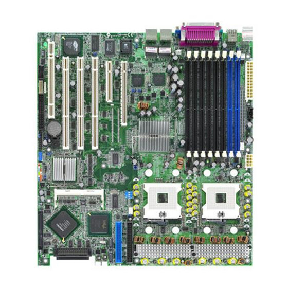
2.2.4 2.2.4 2.2.4 Motherboard layouts Motherboard layouts Motherboard layouts 2.2.4 2.2.4 Motherboard layouts Motherboard layouts NCL-DE/SCSI model NCL-DE/SCSI model NCL-DE/SCSI model NCL-DE/SCSI model NCL-DE/SCSI model 33cm (13in) ATXPWR1 ATX12V1 PS/2 PSUSMB1 T: Mouse B: Keyboard CPU_FAN1 REAR_FAN2 DDR DIMM_B4 (64/72 bit, 240-pin module) USB1 KBPWR1 USB2... - Page 27 NCL-DE/1U model NCL-DE/1U model NCL-DE/1U model NCL-DE/1U model NCL-DE/1U model 33cm (13in) ATXPWR1 ATX12V1 PS/2 PSUSMB1 T: Mouse B: Keyboard CPU_FAN1 REAR_FAN2 DDR DIMM_B4 (64/72 bit, 240-pin module) USB1 KBPWR1 USB2 DDR DIMM_A4 (64/72 bit, 240-pin module) FM_CPU1 DDR DIMM_B3 (64/72 bit, 240-pin module) USBPW12 DDR DIMM_A3 (64/72 bit, 240-pin module) DDR DIMM_B2 (64/72 bit, 240-pin module)
-
Page 28: Layout Contents
2.2.5 2.2.5 2.2.5 Layout contents Layout contents Layout contents 2.2.5 2.2.5 Layout contents Layout contents S l o t s / S o c k e t s S l o t s / S o c k e t s S l o t s / S o c k e t s P a g e P a g e... - Page 29 I n t e r n a l c o n n e c t o r s I n t e r n a l c o n n e c t o r s I n t e r n a l c o n n e c t o r s I n t e r n a l c o n n e c t o r s I n t e r n a l c o n n e c t o r s P a g e...
-
Page 30: Installing The Cpu
The motherboard comes with surface mount 604-pin Zero Insertion Force (ZIF) sockets. The sockets are designed for the Intel ® Xeon™ processor in the 604-pin package with 1 MB L2 cache. The new generation Xeon™ processor supports 800 MHz system bus and Extended Memory 64-bit Technology (EM64T). - Page 31 Position the CPU above the socket as shown. Carefully insert the CPU into the socket until it fits in place. The CPU fits only in one correct orientation. DO NOT force the CPU into the socket to prevent bending the pins and damaging the CPU! M a r k e d c o r n e r M a r k e d c o r n e r...
-
Page 32: Installing The Cpu Heatsink And Fan
2.3.2 2.3.2 2.3.2 Installing the CPU heatsink and fan Installing the CPU heatsink and fan Installing the CPU heatsink and fan 2.3.2 2.3.2 Installing the CPU heatsink and fan Installing the CPU heatsink and fan The Intel ® Xeon™ processors require an Intel certified heatsink and fan assembly to ensure optimum thermal condition and performance. - Page 33 Use a Phillips screwdriver to tighten the four heatsink screws in a diagonal sequence. Connect the fan cable to the 4-pin connector labeled CPU_FAN1. Do not forget to connect the CPU fan connector! Hardware monitoring errors may occur if you fail to plug this connector. CPU_FAN1 connector Repeat steps 1 to 3 to install...
-
Page 34: System Memory
Always install DIMMs with the same CAS latency. For optimum compatibility, it is recommended that you obtain memory modules from the same vendor. Refer to the DDR2 Qualified Vendors List at the ASUS web site. • Due to chipset resource allocation, the system may detect less than 16 GB system memory when you installed eight 2 GB DDR2 memory modules. - Page 35 Single rank population Single rank population Single rank population Single rank population Single rank population M C H M C H M C H M C H M C H Single and dual rank mixing Single and dual rank mixing Single and dual rank mixing Single and dual rank mixing Single and dual rank mixing...
-
Page 36: Installing A Dimm
2.4.3 2.4.3 2.4.3 Installing a DIMM Installing a DIMM Installing a DIMM 2.4.3 2.4.3 Installing a DIMM Installing a DIMM Make sure to unplug the power supply before adding or removing DIMMs or other system components. Failure to do so may cause severe damage to both the motherboard and the components. -
Page 37: Installing An Expansion Card
In the future, you may need to install expansion cards. The following sub-sections describe the slots and the expansion cards that they support. Make sure to unplug the power cord before adding or removing expansion cards. Failure to do so may cause you physical injury and damage motherboard components. -
Page 38: Interrupt Assignments
2.5.3 2.5.3 2.5.3 Interrupt assignments Interrupt assignments Interrupt assignments 2.5.3 2.5.3 Interrupt assignments Interrupt assignments Standard interrupt assignments Standard interrupt assignments Standard interrupt assignments Standard interrupt assignments Standard interrupt assignments I R Q I R Q I R Q I R Q I R Q P r i o r i t y P r i o r i t y... -
Page 39: Pci/Pci-X Slots
2.5.4 2.5.4 2.5.4 PCI/PCI-X slots PCI/PCI-X slots PCI/PCI-X slots 2.5.4 2.5.4 PCI/PCI-X slots PCI/PCI-X slots (For NCL-DE/SCSI model only) (For NCL-DE/SCSI model only) (For NCL-DE/SCSI model only) (For NCL-DE/SCSI model only) (For NCL-DE/SCSI model only) The PCI/PCI-X slots support cards such as a LAN card, SCSI card, USB card, and other cards that comply with PCI 2.3 and PCI-X 1.0... -
Page 40: Pci Express X16 Slot
(For NCL-DE/1U model only) (For NCL-DE/1U model only) The Mini-PCI socket on the motherboard supports an ASUS ® Server Management Board. P C I E x p r e s s x 1 6 s l o t P C I E x p r e s s x 1 6 s l o t... -
Page 41: Jumpers
The grayed out components in the illustrations are present only in NCL-DE/SCSI model. 1 . 1 . C l e a r R T C R A M ( C L R T C 1 ) C l e a r R T C R A M ( C L R T C 1 ) C l e a r R T C R A M ( C L R T C 1 ) C l e a r R T C R A M ( C L R T C 1 ) C l e a r R T C R A M ( C L R T C 1 ) - Page 42 2 . 2 . C P U f a n p i n s e l e c t i o n ( 3 - p i n F M _ C P U 1 , F M _ C P U 2 ) C P U f a n p i n s e l e c t i o n ( 3 - p i n F M _ C P U 1 , F M _ C P U 2 ) C P U f a n p i n s e l e c t i o n ( 3 - p i n F M _ C P U 1 , F M _ C P U 2 ) C P U f a n p i n s e l e c t i o n ( 3 - p i n F M _ C P U 1 , F M _ C P U 2 )
- Page 43 4 . 4 . K e y b o a r d p o w e r ( 3 - p i n K B P W R 1 ) K e y b o a r d p o w e r ( 3 - p i n K B P W R 1 ) K e y b o a r d p o w e r ( 3 - p i n K B P W R 1 ) K e y b o a r d p o w e r ( 3 - p i n K B P W R 1 ) K e y b o a r d p o w e r ( 3 - p i n K B P W R 1 )
- Page 44 6 . 6 . G i g a b i t L A N c o n t r o l l e r s e t t i n g ( 3 - p i n L A N 1 _ E N 1 ) G i g a b i t L A N c o n t r o l l e r s e t t i n g ( 3 - p i n L A N 1 _ E N 1 ) G i g a b i t L A N c o n t r o l l e r s e t t i n g ( 3 - p i n L A N 1 _ E N 1 ) G i g a b i t L A N c o n t r o l l e r s e t t i n g ( 3 - p i n L A N 1 _ E N 1 )
- Page 45 8 . 8 . S C S I c o n t r o l l e r s e t t i n g ( 3 - p i n S C S I _ E N 1 ) S C S I c o n t r o l l e r s e t t i n g ( 3 - p i n S C S I _ E N 1 ) S C S I c o n t r o l l e r s e t t i n g ( 3 - p i n S C S I _ E N 1 ) S C S I c o n t r o l l e r s e t t i n g ( 3 - p i n S C S I _ E N 1 )
-
Page 46: Rear Panel Connectors
2.7.1 2.7.1 2.7.1 2.7.1 2.7.1 Rear panel connectors Rear panel connectors Rear panel connectors Rear panel connectors Rear panel connectors 1 . 1 . P S / 2 m o u s e p o r t ( g r e e n ) . P S / 2 m o u s e p o r t ( g r e e n ) . -
Page 47: Internal Connectors
2.7.2 2.7.2 2.7.2 Internal connectors Internal connectors Internal connectors 2.7.2 2.7.2 Internal connectors Internal connectors 1 . 1 . F l o p p y d i s k d r i v e c o n n e c t o r ( 3 4 - 1 p i n F L O P P Y 1 ) F l o p p y d i s k d r i v e c o n n e c t o r ( 3 4 - 1 p i n F L O P P Y 1 ) F l o p p y d i s k d r i v e c o n n e c t o r ( 3 4 - 1 p i n F L O P P Y 1 ) F l o p p y d i s k d r i v e c o n n e c t o r ( 3 4 - 1 p i n F L O P P Y 1 ) -
Page 48: Hard Disk Drives
3 . 3 . S e r i a l A T A c o n n e c t o r s ( 7 - p i n S A T A 1 , S A T A 2 ) S e r i a l A T A c o n n e c t o r s ( 7 - p i n S A T A 1 , S A T A 2 ) S e r i a l A T A c o n n e c t o r s ( 7 - p i n S A T A 1 , S A T A 2 ) S e r i a l A T A c o n n e c t o r s ( 7 - p i n S A T A 1 , S A T A 2 ) - Page 49 4 . 4 . U l t r a 3 2 0 S C S I c o n n e c t o r s ( t w o 6 8 - p i n S C S I A 1 , S C S I B 1 ) U l t r a 3 2 0 S C S I c o n n e c t o r s ( t w o 6 8 - p i n S C S I A 1 , S C S I B 1 ) U l t r a 3 2 0 S C S I c o n n e c t o r s ( t w o 6 8 - p i n S C S I A 1 , S C S I B 1 ) U l t r a 3 2 0 S C S I c o n n e c t o r s ( t w o 6 8 - p i n S C S I A 1 , S C S I B 1 )
- Page 50 5 . 5 . H a r d d i s k a c t i v i t y L E D c o n n e c t o r ( 4 - p i n H D L E D 1 ) H a r d d i s k a c t i v i t y L E D c o n n e c t o r ( 4 - p i n H D L E D 1 ) H a r d d i s k a c t i v i t y L E D c o n n e c t o r ( 4 - p i n H D L E D 1 ) H a r d d i s k a c t i v i t y L E D c o n n e c t o r ( 4 - p i n H D L E D 1 )
- Page 51 7 . 7 . S e r i a l p o r t c o n n e c t o r ( 1 0 - 1 p i n C O M 2 ) S e r i a l p o r t c o n n e c t o r ( 1 0 - 1 p i n C O M 2 ) S e r i a l p o r t c o n n e c t o r ( 1 0 - 1 p i n C O M 2 ) S e r i a l p o r t c o n n e c t o r ( 1 0 - 1 p i n C O M 2 ) S e r i a l p o r t c o n n e c t o r ( 1 0 - 1 p i n C O M 2 )
- Page 52 B M C c o n n e c t o r ( 1 6 - p i n B M C C O N N 1 ) This connector is for the ASUS server management card, if available. BMCCONN1 NCL-DE Series BMC connector 1 0 .
- Page 53 1 1 . 1 1 . 1 1 . P o w e r s u p p l y S M B u s c o n n e c t o r ( 5 - p i n P S U S M B 1 ) P o w e r s u p p l y S M B u s c o n n e c t o r ( 5 - p i n P S U S M B 1 ) P o w e r s u p p l y S M B u s c o n n e c t o r ( 5 - p i n P S U S M B 1 ) P o w e r s u p p l y S M B u s c o n n e c t o r ( 5 - p i n P S U S M B 1 )
- Page 54 1 2 . 1 2 . 1 2 . A T X A T X A T X power connectors (24-pin ATXPWR1, A T X power connectors (24-pin ATXPWR1, power connectors (24-pin ATXPWR1, power connectors (24-pin ATXPWR1, 8 8 8 8 8- p i n - p i n - p i n - p i n A T X 1 2 V 1...
- Page 55 1 3 . 1 3 . 1 3 . S y s t e m p a n e l c o n n e c t o r ( 2 0 - p i n P A N E L 1 ) S y s t e m p a n e l c o n n e c t o r ( 2 0 - p i n P A N E L 1 ) S y s t e m p a n e l c o n n e c t o r ( 2 0 - p i n P A N E L 1 ) S y s t e m p a n e l c o n n e c t o r ( 2 0 - p i n P A N E L 1 )
- Page 56 1 5 . 1 5 . 1 5 . A u x i l i a r y p a n e l c o n n e c t o r ( 2 0 - p i n A U X _ P A N E L 1 ) A u x i l i a r y p a n e l c o n n e c t o r ( 2 0 - p i n A U X _ P A N E L 1 ) A u x i l i a r y p a n e l c o n n e c t o r ( 2 0 - p i n A U X _ P A N E L 1 ) A u x i l i a r y p a n e l c o n n e c t o r ( 2 0 - p i n A U X _ P A N E L 1 )
- Page 57 This chapter describes the power up sequence, and ways of shutting down the system.
-
Page 58: Starting Up For The First Time
Starting up for the first time ..........3-1 Turning off the computer ............. 3-2 A S U S N C L - D E S e r i e s A S U S N C L - D E S e r i e s A S U S N C L - D E S e r i e s A S U S N C L - D E S e r i e s A S U S N C L - D E S e r i e s... - Page 59 After making all the connections, replace the system case cover. Be sure that all switches are off. Connect the power cord to the power connector at the back of the system chassis. Connect the power cord to a power outlet that is equipped with a surge protector.
-
Page 60: Using The Os Shut Down Function
3.2.1 3.2.1 3.2.1 3.2.1 3.2.1 Using the OS shut down function Using the OS shut down function Using the OS shut down function Using the OS shut down function Using the OS shut down function If you are using Windows ®... - Page 61 This chapter tells how to change the system settings through the BIOS Setup menus. Detailed descriptions of the BIOS parameters are also provided.
-
Page 62: Managing And Updating Your Bios
Managing and updating your BIOS ........4-1 BIOS setup program ............4-10 Main menu ................4-13 Advanced menu ..............4-18 Server menu ............... 4-32 Security ................4-34 Boot menu ................4-37 Exit menu ................4-40 A S U S N C L - D E S e r i e s A S U S N C L - D E S e r i e s A S U S N C L - D E S e r i e s A S U S N C L - D E S e r i e s... -
Page 63: Creating A Bootable Floppy Disk
Refer to the corresponding sections for details on these utilities. Save a copy of the original motherboard BIOS file to a bootable floppy disk in case you need to restore the BIOS in the future. Copy the original motherboard BIOS using the ASUS Update or AFUDOS utilities. 4.1.1 4.1.1 4.1.1... -
Page 64: Afudos Utility
Press <Enter>. The utility copies the current BIOS file to the floppy disk. A:\>afudos /oOLDBIOS1.rom AMI Firmware Update Utility - Version 1.19(ASUS V2.07(03.11.24BB)) Copyright (C) 2002 American Megatrends, Inc. All rights reserved. Reading flash ..done Write to file..ok A:\>... - Page 65 Updating the BIOS file To update the BIOS file using the AFUDOS utility: Visit the ASUS website (www.asus.com) and download the latest BIOS file for the motherboard. Save the BIOS file to a bootable floppy disk. Write the BIOS filename on a piece of paper. You need to type the exact BIOS filename at the DOS prompt.
- Page 66 The utility returns to the DOS prompt after the BIOS update process is completed. Reboot the system from the hard disk drive. A:\>afudos /iNCLDESCI.ROM AMI Firmware Update Utility - Version 1.19(ASUS V2.07(03.11.24BB)) Copyright (C) 2002 American Megatrends, Inc. All rights reserved. WARNING!! Do not turn off power during flash BIOS Reading file ..
-
Page 67: Asus Crashfree Bios 2 Utility
ASUS CrashFree BIOS 2 utility ASUS CrashFree BIOS 2 utility The ASUS CrashFree BIOS 2 is an auto recovery tool that allows you to restore the BIOS file when it fails or gets corrupted during the updating process. You can update a corrupted BIOS file using the motherboard support CD or the floppy disk that contains the updated BIOS file. - Page 68 Restart the system after the utility completes the updating process. The recovered BIOS may not be the latest BIOS version for this motherboard. Visit the ASUS website (www.asus.com) to download the latest BIOS file. 4 - 6...
-
Page 69: Asus Update Utility
ASUS Update utility 4.1.4 4.1.4 ASUS Update utility ASUS Update utility The ASUS Update is a utility that allows you to manage, save, and update the motherboard BIOS in Windows ® environment. The ASUS Update utility allows you to: •... - Page 70 Updating the BIOS through the Internet Updating the BIOS through the Internet Updating the BIOS through the Internet To update the BIOS through the Internet: Launch the ASUS Update utility from the Windows ® desktop by clicking S t a r t S t a r t >...
- Page 71 A S U S U p d a t e A S U S U p d a t e A S U S U p d a t e. The ASUS Update main window appears. A S U S U p d a t e...
-
Page 72: Bios Setup Program
The BIOS setup screens shown in this section are for reference purposes only, and may not exactly match what you see on your screen. • Visit the ASUS website (www.asus.com) to download the latest BIOS file for this motherboard. 4 - 1 0 4 - 1 0... -
Page 73: Bios Menu Screen
Legacy Diskette A [1.44M, 3.5 in] Use [+] or [-] to configure system time. IDE Configuration Primary IDE Master [ST32122A] Primary IDE Slave [ASUS CD-S520A] Secondary IDE Master [Not Detected] Secondary IDE Slave [Not Detected] Select Screen Third IDE Master [Not Detected]... -
Page 74: Menu Items
4.2.4 4.2.4 4.2.4 Menu items Menu items Menu items 4.2.4 4.2.4 Menu items Menu items The highlighted item on the menu BIOS SETUP UTILITY Main Advanced Server Security Boot Exit Use [ENTER], [TAB], bar displays the specific items for System Date [Mon 05/30/2005] or [SHIFT-TAB] to System Time... -
Page 75: Main Menu
[1.44M, 3.5 in] IDE Configuration Use [+] or [-] to Primary IDE Master [ST32122A] configure system time. Primary IDE Slave [ASUS CD-S520A] Secondary IDE Master [Not Detected] Secondary IDE Slave [Not Detected] Third IDE Master [Not Detected] Fourth IDE Master... -
Page 76: Ide Configuration
4.3.4 4.3.4 4.3.4 IDE Configuration IDE Configuration IDE Configuration 4.3.4 4.3.4 IDE Configuration IDE Configuration The items in this menu allow you to set or change the configurations for the IDE devices installed in the system. Select an item then press <Enter> if you wish to configure the item. -
Page 77: Primary/Secondary Ide Master/Slave, Third, And Fourth Ide Master
4.3.5 4.3.5 4.3.5 Primary/Secondary IDE Master/Slave, Primary/Secondary IDE Master/Slave, Primary/Secondary IDE Master/Slave, 4.3.5 4.3.5 Primary/Secondary IDE Master/Slave, Primary/Secondary IDE Master/Slave, Third, and Fourth IDE Master Third, and Fourth IDE Master Third, and Fourth IDE Master Third, and Fourth IDE Master Third, and Fourth IDE Master The BIOS automatically detects the connected IDE devices. -
Page 78: System Information
ESC Exit v02.58 (C)Copyright 1985-2004, American Megatrends, Inc. Model Name Model Name Model Name Model Name Model Name Displays the auto-detected ASUS motherboard model (either NCL-DE/SCSI, or NCL-DE/1U). Model ID Model ID Model ID Model ID Model ID Displays the auto-detected identification number of the motherboard. - Page 79 Processor Information Processor Information Processor Information Processor Information Processor Information Displays the auto-detected information about the installed CPU or CPUs. BIOS SETUP UTILITY Main Processor Information *** CPU1 : Brand Intel(R) Xeon(TM) CPU 3.60GHz ID/uCode 0F34h/014h Ratio Value Actual 18 Max 18 Cache Value L1/16KB L2/1024KB...
-
Page 80: Advanced Menu
The Advanced menu items allow you to change the settings for the CPU and other system devices. Take caution when changing the settings of the Advanced menu items. Incorrect field values can cause the system to malfunction. BIOS SETUP UTILITY Advanced Advanced Settings Configure CPU. - Page 81 MPS Table Version [1.4] MPS Table Version [1.4] MPS Table Version [1.4] MPS Table Version [1.4] MPS Table Version [1.4] Allows you to select the multi-processor system version. Configuration options: [1.1] [1.4] Hyper-Threading Technology [Enabled] Hyper-Threading Technology [Enabled] Hyper-Threading Technology [Enabled] Hyper-Threading Technology [Enabled] Hyper-Threading Technology [Enabled] Allows you to enable or disable the processor Hyper-Threading Technology.
-
Page 82: Chipset Configuration
4.4.2 4.4.2 4.4.2 Chipset Configuration Chipset Configuration Chipset Configuration 4.4.2 4.4.2 Chipset Configuration Chipset Configuration The Chipset Configuration menu allows you to change the advanced chipset settings. Select an item then press <Enter> to display the sub-menu. BIOS SETUP UTILITY Advanced Advanced Chipset Settings Options for NB. - Page 83 NorthBridge Configuration NorthBridge Configuration NorthBridge Configuration NorthBridge Configuration NorthBridge Configuration The NorthBridge Configuration menu allows you to change the Northbridge related settings. BIOS SETUP UTILITY Advanced NorthBridge Chipset Configuration ENABLE: Allow remapping of DIMM SPEED: DDR2 400 overlapped PCI memory Memory Remap Feature [Enabled] above the total...
-
Page 84: Onboard Devices Configuration
4.4.3 4.4.3 4.4.3 Onboard Devices Configuration Onboard Devices Configuration Onboard Devices Configuration 4.4.3 4.4.3 Onboard Devices Configuration Onboard Devices Configuration BIOS SETUP UTILITY Advanced Advanced Onboard Devices Settings Configure the USB support. USB Configuration Super IO Configuration Select Screen Select Item Change Option General Help F10 Save and Exit... - Page 85 Legacy USB Support [Auto] Legacy USB Support [Auto] Legacy USB Support [Auto] Legacy USB Support [Auto] Legacy USB Support [Auto] Allows you to enable or disable support for legacy USB devices. Setting to [Auto] allows the system to detect the presence of legacy USB devices at startup.
- Page 86 Super IO Configuration Super IO Configuration Super IO Configuration Super IO Configuration Super IO Configuration BIOS SETUP UTILITY Advanced Configure Win83627THF Super IO Chipset Allows BIOS to select Serial Port1 Base Serial Port1 Address [3F8/IRQ4] Addresses. Serial Port2 Address [2F8/IRQ3] Serial Port2 Mode [Normal] Parallel Port Address...
- Page 87 E P P V e r s i o n [ 1 . 9 ] E P P V e r s i o n [ 1 . 9 ] E P P V e r s i o n [ 1 . 9 ] E P P V e r s i o n [ 1 .
-
Page 88: Pci/Pnp Configuration
4.4.4 4.4.4 4.4.4 PCI/PnP Configuration PCI/PnP Configuration PCI/PnP Configuration 4.4.4 4.4.4 PCI/PnP Configuration PCI/PnP Configuration The PCI/PnP Configuration menu items allow you to change the advanced settings for PCI/PnP devices. The menu includes setting the IRQ and DMA channel resources for either PCI/PnP or legacy ISA devices, and setting the memory size block for legacy ISA devices. -
Page 89: Power Configuration
PCI IDE BusMaster [Enabled] PCI IDE BusMaster [Enabled] PCI IDE BusMaster [Enabled] PCI IDE BusMaster [Enabled] PCI IDE BusMaster [Enabled] Allows BIOS to use PCI bus mastering when reading/writing to IDE devices. Configuration options: [Disabled] [Enabled] IRQ-xx assigned to [PCI Device] IRQ-xx assigned to [PCI Device] IRQ-xx assigned to [PCI Device] IRQ-xx assigned to [PCI Device]... - Page 90 APM Configuration APM Configuration APM Configuration APM Configuration APM Configuration BIOS SETUP UTILITY Advanced APM Configuration Enable or disable APM. Power Management/APM [Enabled] Video Power Down Mode [Suspend] Hard Disk Power Down Mode [Suspend] Suspend Time Out (Minute) [Disabled] Throttle Slow Clock Ratio [50%] Power Button Function [On/Off]...
- Page 91 Restore on AC Power Loss [Last State] Restore on AC Power Loss [Last State] Restore on AC Power Loss [Last State] Restore on AC Power Loss [Last State] Restore on AC Power Loss [Last State] When set to Power Off, the system goes into off state after an AC power loss.
-
Page 92: Hardware Monitor
4.4.6 4.4.6 4.4.6 Hardware Monitor Hardware Monitor Hardware Monitor 4.4.6 4.4.6 Hardware Monitor Hardware Monitor BIOS SETUP UTILITY Advanced Hardware Monitor CPU1 Temperature. CPU1 Temperature [49ºC/120ºF] CPU2 Temperature [47ºC/114ºF] MB Temperature [39ºC/102ºF] CPU1 Fan Speed [5038RPM] CPU2 Fan Speed [5045RPM] Front1 Fan Speed [N/A] Front2 Fan Speed... - Page 93 Smart Fan Control [Enabled] Smart Fan Control [Enabled] Smart Fan Control [Enabled] Allows you to enable or disable the ASUS Q-Fan feature that smartly adjusts the fan speeds for more efficient system operation. Configuration options: [Disabled] [Enabled] The C P U 1 T e m p e r a t u r e...
-
Page 94: Security
The Server menu items allow you to customize the server features. BIOS SETUP UTILITY Main Advanced Server Security Boot Exit Server Features Configure Remote Access. Remote Access Configuration Select Screen Select Item Change Option General Help F10 Save and Exit ESC Exit v02.58 (C)Copyright 1985-2004, American Megatrends, Inc. - Page 95 Remote Access [Disabled] Remote Access [Disabled] Remote Access [Disabled] Remote Access [Disabled] Remote Access [Disabled] Enables or disables the remote access feature. Configuration options: [Disabled] [Enabled] When the R e m o t e A c c e s s R e m o t e A c c e s s R e m o t e A c c e s s R e m o t e A c c e s s item is set to [Enabled], the following...
- Page 96 The Security menu items allow you to change the system security settings. Select an item then press <Enter> to display the configuration options. BIOS SETUP UTILITY Main Advanced Server Security Boot Exit Security Settings <Enter> to change password. Supervisor Password : Not Installed <Enter>...
- Page 97 After you have set a supervisor password, the other items appear to allow you to change other security settings. BIOS SETUP UTILITY Main Advanced Server Security Boot Exit Security Settings <Enter> to change password. Supervisor Password : Installed <Enter> again to User Password : Not Installed disable password.
- Page 98 Clear User Password Clear User Password Clear User Password Clear User Password Clear User Password Select this item to clear the user password. Password Check [Setup] Password Check [Setup] Password Check [Setup] Password Check [Setup] Password Check [Setup] When set to [Setup], BIOS checks for user password when accessing the Setup utility.
-
Page 99: Boot Menu
Boot Device Priority Specifies the boot sequence from the 1st Boot Device [1st FLOPPY DRIVE] available devices. 2nd Boot Device [PS-ASUS CD-S520/A] 3rd Boot Device [PM-ST32122A] A device enclosed in parenthesis has been disabled in the corresponding menu. Select Screen... -
Page 100: Boot Settings Configuration
Full Logo display [Enabled] Allows you to enable or disable the full screen logo display feature. Configuration options: [Disabled] [Enabled] Set this item to [Enabled] to use the ASUS MyLogo2™ feature. Bootup Num-Lock [On] Bootup Num-Lock [On] Bootup Num-Lock [On]... - Page 101 Wait for ‘F1’ If Error [Enabled] Wait for ‘F1’ If Error [Enabled] Wait for ‘F1’ If Error [Enabled] Wait for ‘F1’ If Error [Enabled] Wait for ‘F1’ If Error [Enabled] When set to Enabled, the system waits for the F1 key to be pressed when error occurs.
-
Page 102: Exit Menu
The Exit menu items allow you to load the optimal or failsafe default values for the BIOS items, and save or discard your changes to the BIOS items. BIOS SETUP UTILITY Main Advanced Server Security Boot Exit Exit Options Exit system setup after saving the Exit &... - Page 103 Load Setup Defaults Load Setup Defaults Load Setup Defaults Load Setup Defaults Load Setup Defaults Select this option then press <Enter> to load the optimized settings for each of the Setup menu items. When a confirmation window appears, select [ O K ] [ O K ] [ O K ] [ O K ] then press <Enter>...
- Page 104 4 - 4 2 4 - 4 2 C h a p t e r 4 : B I O S s e t u p C h a p t e r 4 : B I O S s e t u p 4 - 4 2 4 - 4 2 4 - 4 2...
- Page 105 This chapter provides instructions for setting up, creating, and configuring RAID sets using the available utilities.
-
Page 106: Setting Up Raid
Setting up RAID ..............5-1 LSI Logic Embedded SATA RAID Setup Utility ...... 5-4 Global Array Manager ............5-26 Adaptec SCSISelect(TM) Utility! (NCL-DE/SCSI model only) ..........5-27 A S U S N C L - D E S e r i e s A S U S N C L - D E S e r i e s A S U S N C L - D E S e r i e s A S U S N C L - D E S e r i e s... -
Page 107: Raid Definitions
The motherboard comes with the following RAID solutions: NCL-DE/1U NCL-DE/1U NCL-DE/1U NCL-DE/1U NCL-DE/1U • LSI Logic Embedded SATA RAID LSI Logic Embedded SATA RAID LSI Logic Embedded SATA RAID LSI Logic Embedded SATA RAID technology embedded in the LSI Logic Embedded SATA RAID Intel ®... -
Page 108: Installing Hard Disk Drives
5.1.2 5.1.2 5.1.2 Installing hard disk drives Installing hard disk drives Installing hard disk drives 5.1.2 5.1.2 Installing hard disk drives Installing hard disk drives The motherboard supports Serial ATA (both models) and SCSI hard disk drives (NCL-DE/SCSI model only) for RAID set configuration. For optimal performance, install identical drives of the same model and capacity when creating a disk array. -
Page 109: Raid Configuration Utilities
5.1.4 5.1.4 5.1.4 RAID configuration utilities RAID configuration utilities RAID configuration utilities 5.1.4 5.1.4 RAID configuration utilities RAID configuration utilities Depending on the RAID connectors that you use, you can create a RAID set using the utilities embedded in each RAID controller. For example, use the L S I L o g i c E m b e d d e d S A T A R A I D S e t u p U t i l i t y L S I L o g i c E m b e d d e d S A T A R A I D S e t u p U t i l i t y L S I L o g i c E m b e d d e d S A T A R A I D S e t u p U t i l i t y... - Page 110 The LSI Logic Embedded SATA RAID Setup Utility allows you to create RAID 0 and RAID 1 set(s) from SATA hard disk drives connected to the SATA connectors supported by the motherboard ICH5R Southbridge chip. To enter the LSI Logic Embedded SATA RAID Setup Utility: Turn on the system after installing all the SATA hard disk drives.
-
Page 111: Creating A Raid Set
M e n u M e n u M e n u M e n u M e n u D e s c r i p t i o n D e s c r i p t i o n D e s c r i p t i o n D e s c r i p t i o n D e s c r i p t i o n... - Page 112 The A R R A Y S E L E C T I O N M E N U A R R A Y S E L E C T I O N M E N U A R R A Y S E L E C T I O N M E N U A R R A Y S E L E C T I O N M E N U displays the available drives A R R A Y S E L E C T I O N M E N U connected to the SATA ports.
- Page 113 Press <F10>, select the configurable array, then press <SpaceBar>. The logical drive information appears including a Logical Drive menu that allows you to change the logical drive parameters. A S U S N C L - D E S e r i e s A S U S N C L - D E S e r i e s 5 - 7 5 - 7...
- Page 114 Select R A I D R A I D R A I D R A I D from the L o g i c a l D r i v e L o g i c a l D r i v e L o g i c a l D r i v e menu, then press <Enter>.
- Page 115 10. When finished setting the selected logical drive configuration, select A c c e p t A c c e p t from the menu, then press <Enter>. A c c e p t A c c e p t A c c e p t 11.
- Page 116 Using New Configuration Using New Configuration Using New Configuration Using New Configuration Using New Configuration When a RAID set is already existing, using the N e w C o n f i g u r a t i o n N e w C o n f i g u r a t i o n N e w C o n f i g u r a t i o n N e w C o n f i g u r a t i o n...
-
Page 117: Adding Or Viewing A Raid Configuration
5.2.2 5.2.2 5.2.2 Adding or viewing a RAID configuration Adding or viewing a RAID configuration Adding or viewing a RAID configuration 5.2.2 5.2.2 Adding or viewing a RAID configuration Adding or viewing a RAID configuration You can add a new RAID configuration or view an existing configuration V i e w / A d d C o n f i g u r a t i o n V i e w / A d d C o n f i g u r a t i o n using the V i e w / A d d C o n f i g u r a t i o n... - Page 118 Select all the drives required for the RAID set, then press <Enter>. The configurable array appears on screen. Press <F10>, select the configurable array, then press <SpaceBar>. The logical drive information appears including a Logical Drive menu that allows you to change the logical drive parameters. 5 - 1 2 5 - 1 2 C h a p t e r 5 : R A I D c o n f i g u r a t i o n...
- Page 119 Follow steps 6 to 7 of the C r e a t i n g a R A I D s e t : U s i n g E a s y C r e a t i n g a R A I D s e t : U s i n g E a s y C r e a t i n g a R A I D s e t : U s i n g E a s y C r e a t i n g a R A I D s e t : U s i n g E a s y C r e a t i n g a R A I D s e t : U s i n g E a s y...
-
Page 120: Initializing The Logical Drives
5.2.3 5.2.3 5.2.3 Initializing the logical drives Initializing the logical drives Initializing the logical drives 5.2.3 5.2.3 Initializing the logical drives Initializing the logical drives After creating the RAID set(s), you must initialize the logical drives. You I n i t i a l i z e I n i t i a l i z e may initialize the logical drives of a RAID set(s) using the I n i t i a l i z e I n i t i a l i z e... - Page 121 When prompted, press the <SpaceBar> to select Y e s Y e s Y e s Y e s from the Y e s I n i t i a l i z e ? I n i t i a l i z e ? dialog box, then press <Enter>. You may also press I n i t i a l i z e ? I n i t i a l i z e ? I n i t i a l i z e ?
- Page 122 When initialization is completed, press <Esc>. Using the Objects command Using the Objects command Using the Objects command Using the Objects command Using the Objects command O b j e c t s O b j e c t s To initialize the logical drives using the O b j e c t s O b j e c t s O b j e c t s command:...
- Page 123 Select L o g i c a l D r i v e L o g i c a l D r i v e L o g i c a l D r i v e L o g i c a l D r i v e from the O b j e c t s O b j e c t s O b j e c t s sub-menu, then press O b j e c t s...
- Page 124 When prompted, press the <SpaceBar> to select Y e s Y e s Y e s Y e s from the Y e s I n i t i a l i z e ? I n i t i a l i z e ? dialog box, then press <Enter>. You may also press I n i t i a l i z e ? I n i t i a l i z e ? I n i t i a l i z e ?
-
Page 125: Rebuilding Failed Drives
5.2.4 5.2.4 5.2.4 Rebuilding failed drives Rebuilding failed drives Rebuilding failed drives 5.2.4 5.2.4 Rebuilding failed drives Rebuilding failed drives You can manually rebuild failed hard disk drives using the R e b u i l d R e b u i l d R e b u i l d R e b u i l d R e b u i l d... - Page 126 After selecting the drive to rebuild, press <F10>. The indicator for the selected drive now shows R B L D R B L D R B L D. R B L D R B L D When prompted, press <Y> to to rebuild the drive. When rebuild is complete, press any key to continue.
-
Page 127: Checking The Drives For Data Consistency
5.2.5 5.2.5 5.2.5 Checking the drives for data consistency Checking the drives for data consistency Checking the drives for data consistency 5.2.5 5.2.5 Checking the drives for data consistency Checking the drives for data consistency You can check and verify the accuracy of data redundancy in the selected logical drive. - Page 128 When prompted, press the <SpaceBar> to select Y e s Y e s Y e s Y e s from the Y e s C o n s i s t e n c y C h e c k C o n s i s t e n c y C h e c k dialog box, then press <Enter>.
- Page 129 Using the Objects command Using the Objects command Using the Objects command Using the Objects command Using the Objects command O b j e c t s O b j e c t s To check data consistency using the O b j e c t s O b j e c t s O b j e c t s command: From the Management Menu, select O b j e c t s...
-
Page 130: Deleting A Raid Configuration
5.2.6 5.2.6 5.2.6 Deleting a RAID configuration Deleting a RAID configuration Deleting a RAID configuration 5.2.6 5.2.6 Deleting a RAID configuration Deleting a RAID configuration To delete a RAID configuration: C o n f i g u r e C o n f i g u r e C l e a r C l e a r From the Management Menu, select C o n f i g u r e... -
Page 131: Selecting The Boot Drive From A Raid Set
5.2.7 5.2.7 5.2.7 Selecting the boot drive from a RAID set Selecting the boot drive from a RAID set Selecting the boot drive from a RAID set 5.2.7 5.2.7 Selecting the boot drive from a RAID set Selecting the boot drive from a RAID set You must have created a new RAID configuration before you can select the C r e a t i n g a R A I D s e t : U s i n g C r e a t i n g a R A I D s e t : U s i n g... -
Page 132: Enabling The Writecache
5.2.8 5.2.8 5.2.8 Enabling the WriteCache Enabling the WriteCache Enabling the WriteCache 5.2.8 5.2.8 Enabling the WriteCache Enabling the WriteCache You may enable the RAID controller’s W r i t e C a c h e W r i t e C a c h e W r i t e C a c h e W r i t e C a c h e option to improve the W r i t e C a c h e... -
Page 133: (Ncl-De/Scsi Model Only)
(NCL-DE/SCSI model only) The Adaptec SCSISelect(TM) Utility allows you to create RAID 0, 1, and 0+1 set(s) from SCSI hard disk drives connected to the SCSI connector supported by the Adaptec embedded SCSI controller. To enter the Adaptec SCSISelect(TM) Utility!: Turn on the system after installing all the SCSI hard disk drives. -
Page 134: Configuring The Scsi Controller
5.4.1 5.4.1 5.4.1 Configuring the SCSI controller Configuring the SCSI controller Configuring the SCSI controller 5.4.1 5.4.1 Configuring the SCSI controller Configuring the SCSI controller You need to configure the SCSI controller before creating a RAID set. After selecting the SCSI channel to use, the utility prompts you to select from C o n f i g u r e / V i e w C o n f i g u r e / V i e w the available options. -
Page 135: Creating A Raid 0 Set (Stripe)
The screen returns to the options menu. 5.4.3 5.4.3 Creating a RAID 0 set (Stripe) Creating a RAID 0 set (Stripe) 5.4.3 5.4.3 5.4.3 Creating a RAID 0 set (Stripe) Creating a RAID 0 set (Stripe) Creating a RAID 0 set (Stripe) To create a RAID 0 set for Performance: After enabling the HostRAID, the utility returns to the initial menu. - Page 136 The utility displays the installed SCSI hard disk drives status and menu options. When available, the HDD status shows F r e e F r e e F r e e. Press <C C C C C >. F r e e F r e e The utility does not display an installed SCSI HDD(s) with an existing RAID condiguration or is part of an existing RAID set.
- Page 137 Use the arrow keys to select a RAID set member, then press <SpaceBar> to mark. An X X X X X mark appears after the selected HDD. Follow the step 4 to select the other members of the RAID set, then press <Enter>...
- Page 138 If you want to make the array bootable, select Y e s Y e s Y e s from the Y e s Y e s menu, then press <Enter>. When prompted to create the RAID 0 set, select <Yes>, then press <Enter>.
-
Page 139: Creating A Raid 1 Set (Mirror)
5.4.4 5.4.4 5.4.4 Creating a RAID 1 set (Mirror) Creating a RAID 1 set (Mirror) Creating a RAID 1 set (Mirror) 5.4.4 5.4.4 Creating a RAID 1 set (Mirror) Creating a RAID 1 set (Mirror) To create a RAID 1 set for Fault Tolerance: C r e a t i n g a R A I D 0 s e t C r e a t i n g a R A I D 0 s e t Follow steps 1 to 2 of the C r e a t i n g a R A I D 0 s e t... - Page 140 Select C r e a t e n e w R A I D - 1 C r e a t e n e w R A I D - 1 C r e a t e n e w R A I D - 1 C r e a t e n e w R A I D - 1 from the RAID-1 Build Option menu, C r e a t e n e w R A I D - 1 then press <Enter>.
- Page 141 11. The utility builds the RAID 1 set and displays a progress bar at the center of the screen. Press <Esc> if you want to stop the building process. B u i l d C o m p l e t e B u i l d C o m p l e t e A B u i l d C o m p l e t e B u i l d C o m p l e t e...
-
Page 142: Creating A Raid 10 Set (Stripe+Mirror)
5.4.5 5.4.5 5.4.5 Creating a RAID 10 set (Stripe+Mirror) Creating a RAID 10 set (Stripe+Mirror) Creating a RAID 10 set (Stripe+Mirror) 5.4.5 5.4.5 Creating a RAID 10 set (Stripe+Mirror) Creating a RAID 10 set (Stripe+Mirror) To create a RAID 10 set for Fault Tolerance and Performance: After enabling the HostRAID, the utility returns to the initial menu. - Page 143 Select R A I D - 1 0 ( F a u l t T o l e r a n c e , H i g h P e r f o r m a n c e ) R A I D - 1 0 ( F a u l t T o l e r a n c e , H i g h P e r f o r m a n c e ) R A I D - 1 0 ( F a u l t T o l e r a n c e , H i g h P e r f o r m a n c e ) R A I D - 1 0 ( F a u l t T o l e r a n c e , H i g h P e r f o r m a n c e ) from...
- Page 144 Select the stripe size from the menu, then press <Enter>. For server systems, we recommend that you use a lower array block size. For multimedia computer systems used mainly for audio and video editing, we recommend a higher array block size for optimum performance. When prompted, use the keyboard to assign a name for the RAID 10 set, then press <Enter>.
- Page 145 10. The screen displays the information on the created RAID set. Press <Esc> to exit the utility. A S U S N C L - D E S e r i e s A S U S N C L - D E S e r i e s 5 - 3 9 5 - 3 9 A S U S N C L - D E S e r i e s...
-
Page 146: Adding A Spare Drive To A Raid 10 Set
5.4.6 5.4.6 5.4.6 Adding a spare drive to a RAID 10 set Adding a spare drive to a RAID 10 set Adding a spare drive to a RAID 10 set 5.4.6 5.4.6 Adding a spare drive to a RAID 10 set Adding a spare drive to a RAID 10 set To add a spare drive to a RAID 10 set: Press <S S S S S >... -
Page 147: Deleting A Raid 10 Set Spare Drive
The screen displays the information on the added spare drive. Press <Esc> to exit the utility. 5.4.7 5.4.7 5.4.7 Deleting a RAID 10 set spare drive Deleting a RAID 10 set spare drive Deleting a RAID 10 set spare drive 5.4.7 5.4.7 Deleting a RAID 10 set spare drive... - Page 148 The screen displays the available spare drive(s). Use the arrow keys to select the spare drive you want to delete, then press <Enter>. When a confirmation dialogue box appears, select <Yes>, then press <Enter> to delete the spare drive. Press <ESC> to exit the utility. 5 - 4 2 5 - 4 2 C h a p t e r 5 : R A I D c o n f i g u r a t i o n...
-
Page 149: Deleting A Raid Set
5.4.8 5.4.8 5.4.8 Deleting a RAID set Deleting a RAID set Deleting a RAID set 5.4.8 5.4.8 Deleting a RAID set Deleting a RAID set To delete a RAID set: Press <D D D D D > from the C o n f i g u r e / V i e w H o s t R A I D S e t t i n g s C o n f i g u r e / V i e w H o s t R A I D S e t t i n g s C o n f i g u r e / V i e w H o s t R A I D S e t t i n g s C o n f i g u r e / V i e w H o s t R A I D S e t t i n g s... -
Page 150: Rebuilding A Raid Set
5.4.9 5.4.9 5.4.9 Rebuilding a RAID set Rebuilding a RAID set Rebuilding a RAID set 5.4.9 5.4.9 Rebuilding a RAID set Rebuilding a RAID set The rebuild option is available only for RAID 1 and RAID 10 sets. To rebuild a RAID set: From the main menu, select the RAID set you want to rebuild, then press <Enter>. -
Page 151: Verifying A Raid Set Hard Disk Drive
5.4.10 5.4.10 5.4.10 Verifying a RAID set hard disk drive Verifying a RAID set hard disk drive Verifying a RAID set hard disk drive Verifying a RAID set hard disk drive 5.4.10 5.4.10 Verifying a RAID set hard disk drive To verify a RAID set hard disk drive: S C S I D i s k U t i l i t i e s S C S I D i s k U t i l i t i e s... -
Page 152: Making A Raid Set Bootable
Select V e r i f y D i s k M e d i a V e r i f y D i s k M e d i a V e r i f y D i s k M e d i a V e r i f y D i s k M e d i a from the menu, then press <Enter>. - Page 153 Select the RAID set you want to make bootable, then press <Enter>. Press < B > < B > < B > < B > when the RAID set information displays on screen. < B > When prompted, select M a r k M a r k M a r k M a r k...
- Page 154 5 - 4 8 5 - 4 8 C h a p t e r 5 : R A I D c o n f i g u r a t i o n C h a p t e r 5 : R A I D c o n f i g u r a t i o n 5 - 4 8 5 - 4 8 5 - 4 8...
- Page 155 This chapter provides instructions for installing the necessary drivers for different system components.
-
Page 156: Raid Driver Installation
RAID driver installation ............6-1 LAN driver installation ............6-9 VGA driver installation ............6-13 Management applications and utilities installation ..... 6-15 A S U S N C L - D E S e r i e s A S U S N C L - D E S e r i e s A S U S N C L - D E S e r i e s A S U S N C L - D E S e r i e s A S U S N C L - D E S e r i e s... -
Page 157: Creating A Raid Driver Disk
After creating the RAID sets for your server system, you are now ready to install an operating system to the independent hard disk drive or bootable array. This part provides instructions on how to install the RAID controller drivers during OS installation. 6.1.1 6.1.1 6.1.1... -
Page 158: Installing The Raid Controller Driver
6.1.2 6.1.2 6.1.2 Installing the RAID controller driver Installing the RAID controller driver Installing the RAID controller driver 6.1.2 6.1.2 Installing the RAID controller driver Installing the RAID controller driver Windows Windows Windows Windows Windows ® ® ® ® ® 2000/2003 Server OS 2000/2003 Server OS 2000/2003 Server OS... - Page 159 Insert the RAID driver disk you created earlier to the floppy disk drive, then press <Enter>. Select the RAID controller driver from the list, then press <Enter>. I n t e l I n t e l ® ® ® ® ® I C H 5 R L S I L o g i c E m b e d d e d S A T A R A I D I C H 5 R L S I L o g i c E m b e d d e d S A T A R A I D •...
- Page 160 T o a n e x i s t i n g W i n d o w s T o a n e x i s t i n g W i n d o w s T o a n e x i s t i n g W i n d o w s ®...
- Page 161 To verify the RAID controller driver installation: M y C o m p u t e r M y C o m p u t e r Right-click the M y C o m p u t e r M y C o m p u t e r M y C o m p u t e r icon on the Windows ®...
- Page 162 Red Hat Red Hat Red Hat Red Hat Red Hat ® ® ® ® ® Enterprise ver. 3.0 Enterprise ver. 3.0 Enterprise ver. 3.0 Enterprise ver. 3.0 Enterprise ver. 3.0 To install the RAID controller driver when installing Red Hat ®...
- Page 163 Select Y e s Y e s Y e s Y e s using the <Tab> key when asked if you have the driver Y e s disk. Press <Enter> Select f d 0 f d 0 f d 0 f d 0 using the <Tab>...
- Page 164 When prompted, insert the Red Hat ® Enterprise ver. 3.0 RAID driver disk to the floppy disk drive, select O K , O K , O K , O K , then press <Enter>. O K , The drivers for the RAID controller are installed to the system. When asked if you will load additional RAID controller drivers: •...
-
Page 165: Windows 2000/2003 Server
This section provides instructions on how to install the Broadcom ® Gigabit LAN controller drivers. 6.2.1 6.2.1 Windows Windows ® ® ® ® ® 2000/2003 Server 2000/2003 Server 6.2.1 6.2.1 6.2.1 Windows Windows Windows 2000/2003 Server 2000/2003 Server 2000/2003 Server To install the Broadcom ®... - Page 166 Click N e x t N e x t N e x t when the InstallShield Wizard window appears. Follow N e x t N e x t screen instructions to continue installation. 6 - 1 0 6 - 1 0 C h a p t e r 6 : D r i v e r i n s t a l l a t i o n C h a p t e r 6 : D r i v e r i n s t a l l a t i o n 6 - 1 0...
-
Page 167: Red Hat ® Enterprise Ver. 3.0
6.2.2 6.2.2 6.2.2 Red Hat Red Hat Red Hat ® ® ® ® ® Enterprise ver. 3.0 Enterprise ver. 3.0 Enterprise ver. 3.0 6.2.2 6.2.2 Red Hat Red Hat Enterprise ver. 3.0 Enterprise ver. 3.0 Follow these instructions when installing the Broadcom ®... - Page 168 Building the driver from the TAR file Building the driver from the TAR file Building the driver from the TAR file Building the driver from the TAR file Building the driver from the TAR file To build the driver from the TAR file: Create a directory and extract the TAR files: tar xvzf bcm5700-<version>.tar.gz Build the driver bcm5700.o as a loadable module for the running...
-
Page 169: Windows 2000 Server
This section provides instructions on how to install the ATI ® RAGE XL Video Graphics Adapter (VGA) driver. 6.3.1 6.3.1 6.3.1 6.3.1 6.3.1 Windows Windows Windows Windows Windows ® ® ® ® ® 2000 Server 2000 Server 2000 Server 2000 Server 2000 Server You need to manually install the ATI ®... -
Page 170: Windows 2003 Server
6.3.2 6.3.2 6.3.2 Windows Windows Windows ® ® ® ® ® 2003 Server 2003 Server 2003 Server 6.3.2 6.3.2 Windows Windows 2003 Server 2003 Server The Windows ® 2003 Server operating system automatically recognizes the ® RAGE XL VGA driver during system installation. There is no need to install an additional driver(s) to support the onboard VGA. -
Page 171: Running The Support Cd
The support CD that came with the motherboard package contains the drivers, management applications, and utilities that you can install to avail all motherboard features. The contents of the support CD are subject to change at any time without notice. Visit the ASUS website (www.asus.com) for updates. 6.4.1 6.4.1 6.4.1... -
Page 172: Management Software Menu
C o n t a c t C o n t a c t C o n t a c t tab to display the ASUS contact information. You can C o n t a c t also find this information on the inside front cover of this user guide. - Page 173 This appendix includes additional information that you may refer to when configuring the motherboard.
-
Page 174: Ncl-De/Scsi Block Diagram
NCL-DE/SCSI block diagram ..........A-1 NCL-DE/1U block diagram ............ A-2 A S U S N C L - D E S e r i e s A S U S N C L - D E S e r i e s A S U S N C L - D E S e r i e s A S U S N C L - D E S e r i e s A S U S N C L - D E S e r i e s... - Page 175 ATI Rage XL EEPROM SMBus monitor LPC-Bus Super I/O W83627THF-A A S U S N C L - D E S e r i e s A S U S N C L - D E S e r i e s A - 1 A - 1 A S U S N C L - D E S e r i e s...
- Page 176 ATI Rage XL EEPROM SMBus monitor LPC-Bus Super I/O W83627THF-A A - 2 A - 2 A p p e n d i x A : R e f e r e n c e i n f o r m a t i o n A p p e n d i x A : R e f e r e n c e i n f o r m a t i o n A - 2 A - 2...