Table of Contents
Advertisement
Quick Links
Advertisement
Table of Contents

Related Manuals for Asus NCT-DA


Summary of Contents for Asus NCT-DA
- Page 1 NCT-D (A)
- Page 2 Product warranty or service will not be extended if: (1) the product is repaired, modified or altered, unless such repair, modification of alteration is authorized in writing by ASUS; or (2) the serial number of the product is defaced or missing.
-
Page 3: Table Of Contents
Welcome! ................1-1 Package contents ..............1-1 Special features ..............1-2 1.3.1 Product highlights ........... 1-2 1.3.2 Innovative ASUS features ........1-4 Chapter 2: Hardware information Chapter 2: Hardware information Chapter 2: Hardware information Chapter 2: Hardware information Chapter 2: Hardware information Before you proceed .............. - Page 4 Managing and updating your BIOS ........4-1 4.1.1 Creating a bootable floppy disk ......4-1 4.1.2 AFUDOS utility ............4-2 4.1.3 ASUS CrashFree BIOS 2 utility ........ 4-5 4.1.4 ASUS EZ Flash utility ..........4-7 4.1.5 ASUS Update utility ..........4-8 BIOS setup program ............4-11 4.2.1...
- Page 5 Contents 4.4.7 Chipset ..............4-22 4.4.8 Onboard Devices Configuration ......4-24 4.4.9 PCI PnP ..............4-25 Power menu ................ 4-27 4.5.1 Suspend Mode ............4-27 4.5.2 Repost Video on S3 Resume ........ 4-27 4.5.3 ACPI 2.0 Support ..........4-27 4.5.4 ACPI APIC Support ..........
-
Page 6: Notices
Notices Federal Communications Commission Statement Federal Communications Commission Statement Federal Communications Commission Statement Federal Communications Commission Statement Federal Communications Commission Statement This device complies with Part 15 of the FCC Rules. Operation is subject to the following two conditions: • This device may not cause harmful interference, and •... -
Page 7: Safety Information
Safety information Electrical safety Electrical safety Electrical safety Electrical safety Electrical safety • To prevent electrical shock hazard, disconnect the power cable from the electrical outlet before relocating the system. • When adding or removing devices to or from the system, ensure that the power cables for the devices are unplugged before the signal cables are connected. -
Page 8: About This Guide
A S U S w e b s i t e s A S U S w e b s i t e s The ASUS website provides updated information on ASUS hardware and software products. Refer to the ASUS contact information. -
Page 9: Typography
Conventions used in this guide Conventions used in this guide Conventions used in this guide Conventions used in this guide Conventions used in this guide To make sure that you perform certain tasks properly, take note of the following symbols used throughout this manual. D A N G E R / W A R N I N G : D A N G E R / W A R N I N G : D A N G E R / W A R N I N G :... -
Page 10: Nct-D (A) Specifications Summary
1 x PCI-X 66 MHz/64-bit slot (PCI-X 1.0a) 1 x PCI-X 66 MHz/64-bit slot (supports ZCR, PCI-X 1.0a) 1 x PCI 33 MHz/32-bit/5V (PCI 2.3) 1 x WiFi slot (ASUS proprietary) S t o r a g e S t o r a g e... - Page 11 ASUS Server Web-based Management (ASWM) ASUS PC Probe ASUS Live Update Utility Anti-virus software *Specifications are subject to change without notice.
- Page 12 x i i x i i x i i x i i x i i...
-
Page 13: Chapter 1: Product Introduction
This chapter describes the motherboard features and the new technologies it supports. Product introduction... -
Page 14: Chapter Summary
Chapter summary Welcome! ................1-1 Package contents ..............1-1 Special features ..............1-2 A S U S N C T - D A S U S N C T - D A S U S N C T - D A S U S N C T - D A S U S N C T - D... -
Page 15: Welcome
N C T - D ( A ) m o t h e r b o a r d ! The motherboard delivers a host of new features and latest technologies, making it another standout in the long line of ASUS quality motherboards! Before you start installing the motherboard, and hardware devices on it, check the items in your package with the list below. -
Page 16: Special Features
Special features 1.3.1 1.3.1 1.3.1 1.3.1 1.3.1 Product highlights Product highlights Product highlights Product highlights Product highlights Latest processor technology Latest processor technology Latest processor technology Latest processor technology Latest processor technology The motherboard comes with dual 604-pin surface mount ZIF sockets designed for the Intel ®... - Page 17 BCM5751 Gigabit LAN controller uses the PCI Express interface and has network throughput close to Gigabit bandwidth. The motherboard also comes with the ASUS proprietary Wi-Fi slot that supports an optional WiFi-b/g card for your wireless Internet, LAN, and file sharing requirements.
-
Page 18: Innovative Asus Features
ASUS Smart Fan technology ASUS Smart Fan technology ASUS Smart Fan technology The ASUS Smart Fan technology smartly adjusts the fan speeds according to the system loading to ensure quiet, cool, and efficient operation. See page 4-30 for details. 1 - 4... - Page 19 ASUS EZ Flash BIOS ASUS EZ Flash BIOS With the ASUS EZ Flash, you can easily update the system BIOS even before loading the operating system. No need to use a DOS-based utility or boot from a floppy disk. See page 4-7 for details.
- Page 20 1 - 6 1 - 6 C h a p t e r 1 : P r o d u c t i n t r o d u c t i o n C h a p t e r 1 : P r o d u c t i n t r o d u c t i o n 1 - 6 1 - 6 1 - 6...
-
Page 21: Chapter 2: Hardware Information
This chapter lists the hardware setup procedures that you have to perform when installing system components. It includes description of the jumpers and connectors on the motherboard. Hardware information... - Page 22 Chapter summary Before you proceed .............. 2-1 Motherboard overview ............2-2 Central Processing Unit (CPU) ..........2-10 System memory ..............2-14 Expansion slots ..............2-16 Jumpers ................2-19 Connectors ................. 2-24 A S U S N C T - D A S U S N C T - D A S U S N C T - D A S U S N C T - D...
-
Page 23: Before You Proceed
Before you proceed Take note of the following precautions before you install motherboard components or change any motherboard settings. • Unplug the power cord from the wall socket before touching any component. • Use a grounded wrist strap or touch a safely grounded object or to a metal object, such as the power supply case, before handling components to avoid damaging them due to static electricity. -
Page 24: Motherboard Overview
Motherboard overview Before you install the motherboard, study the configuration of your chassis to ensure that the motherboard fits into it. Make sure to unplug the chassis power cord before installing or removing the motherboard. Failure to do so can cause you physical injury and damage motherboard components. -
Page 25: Support Plates For Motherboard
2.2.3 2.2.3 2.2.3 Support plates for motherboard Support plates for motherboard Support plates for motherboard 2.2.3 2.2.3 Support plates for motherboard Support plates for motherboard For additional protection from motherboard breakage due to the weight of the CPU heatsinks, your motherboard package comes with a solution kit that consists of: •... - Page 26 Use a plier to attach four nuts to the bolts on the metal support plate. 5. Align a rubber pad to the rectagular mark on the center of the plate, then press to attach. Remove the adhesive label underneath a plate. 2 - 4 2 - 4 C h a p t e r 2 : H a r d w a r e i n f o r m a t i o n...
- Page 27 Carefully align and place the plate on a rectangular cut on the contour sheet. Make sure that the metal support plates fit perfectly to the rectangular cuts on the contour sheet; otherwise, the CPU heatsink screws would not align to the metal nuts. Repeat steps 4 and 7 to prepare and install the second plate.
- Page 28 The support plates appear as shown when installed. 10. Install the motherboard with the external I/O ports toward the chassis rear panel. The CPU sockets should be right on top of the support plates. H e a t s i n k h o l e m a t c h e d t o H e a t s i n k h o l e m a t c h e d t o H e a t s i n k h o l e m a t c h e d t o H e a t s i n k h o l e m a t c h e d t o...
-
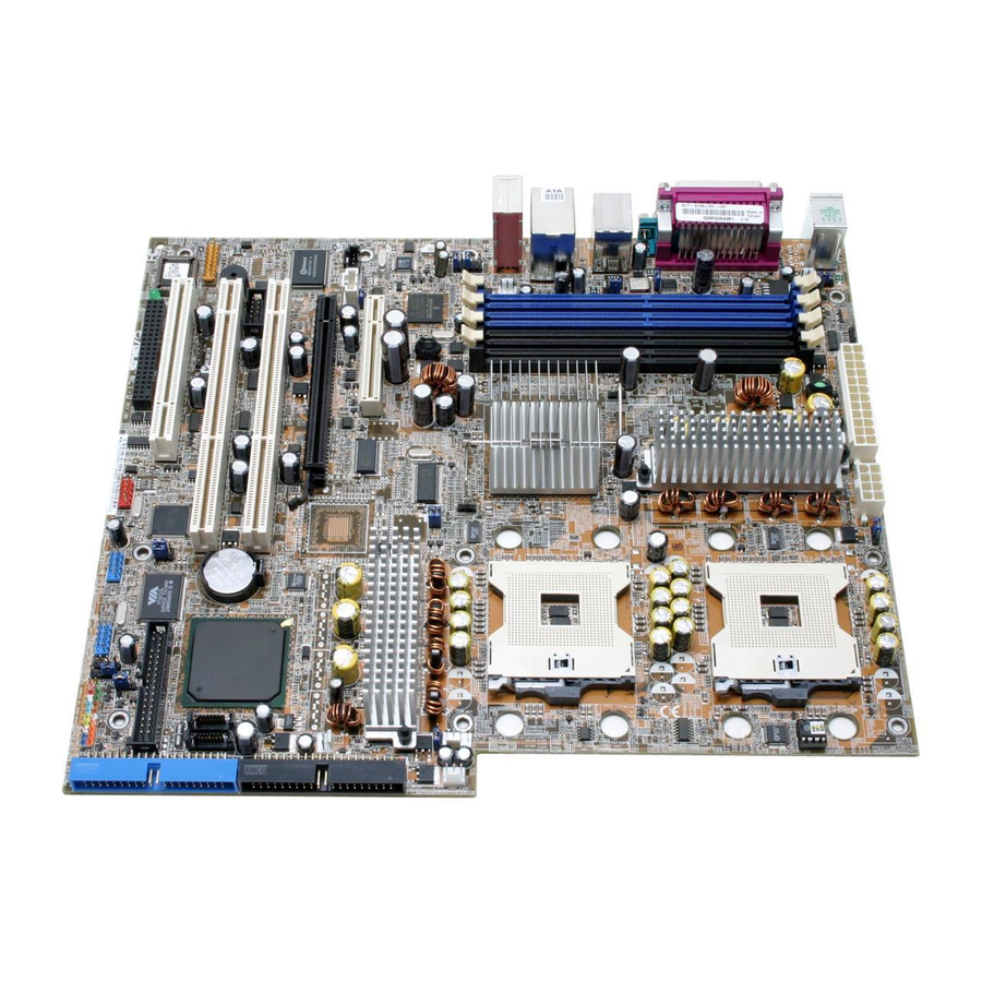
Page 29: Motherboard Layout
2.2.4 2.2.4 2.2.4 Motherboard layout Motherboard layout Motherboard layout 2.2.4 2.2.4 Motherboard layout Motherboard layout 25cm (9.8in) ATXPWR1 ATX12V1 FM_CPU1 PS/2KBMS T: Mouse KBPWR1 B: Keyboard CPU_FAN1 REAR_FAN1 SPDIF CPU1 COM1 USBPW12 Bottom: Top: T:USB4 1394 B:USB3 USB2.0 Intel Top: T: USB1 RJ-45 E7525... -
Page 30: Layout Contents
2.2.5 2.2.5 2.2.5 Layout contents Layout contents Layout contents 2.2.5 2.2.5 Layout contents Layout contents S l o t s S l o t s S l o t s P a g e P a g e P a g e S l o t s S l o t s P a g e... - Page 31 I n t e r n a l c o n n e c t o r s I n t e r n a l c o n n e c t o r s I n t e r n a l c o n n e c t o r s P a g e P a g e P a g e...
-
Page 32: Central Processing Unit (Cpu)
Central Processing Unit (CPU) The motherboard comes with surface mount 604-pin Zero Insertion Force (ZIF) sockets. The sockets are designed for the Intel ® Xeon™ processor in the 604-pin package with 1 MB L2 cache. The new generation Intel ® Xeon™... - Page 33 Position the CPU above the socket as shown. Carefully insert the CPU into the socket until it fits in place. The CPU fits only in one correct orientation. DO NOT force the CPU into the socket to prevent bending the pins and damaging the CPU! M a r k e d c o r n e r M a r k e d c o r n e r...
-
Page 34: Installing The Cpu Heatsink And Fan
2.3.2 2.3.2 2.3.2 Installing the CPU heatsink and fan Installing the CPU heatsink and fan Installing the CPU heatsink and fan 2.3.2 2.3.2 Installing the CPU heatsink and fan Installing the CPU heatsink and fan The Intel ® Xeon™ processors require an Intel ®... - Page 35 Use a Phillips screwdriver to tighten the four heatsink screws in a diagonal sequence. Connect the fan cable to the 4-pin connector labeled CPU_FAN1. Do not forget to connect the CPU fan connector! Hardware monitoring errors may occur if you fail to plug this connector. Repeat steps 1 to 3 to install the other heatsink if you have installed a second CPU, then...
-
Page 36: System Memory
Always install DIMMs with the same CAS latency. For optimum compatibility, it is recommended that you obtain memory modules from the same vendor. Refer to the DDR2 Qualified Vendors List on the ASUS website (www.asus.com) for details. • This motherboard does not support memory modules made up of 128 Mb chips or double sided x16 memory modules. -
Page 37: Installing A Dimm
2.4.3 2.4.3 2.4.3 Installing a DIMM Installing a DIMM Installing a DIMM 2.4.3 2.4.3 Installing a DIMM Installing a DIMM Unplug the power supply before adding or removing DIMMs or other system components. Failure to do so can cause severe damage to both the motherboard and the components. -
Page 38: Expansion Slots
Expansion slots In the future, you may need to install expansion cards. The following sub-sections describe the slots and the expansion cards that they support. Make sure to unplug the power cord before adding or removing expansion cards. Failure to do so may cause you physical injury and damage motherboard components. -
Page 39: Interrupt Assignments
2.5.3 2.5.3 2.5.3 Interrupt assignments Interrupt assignments Interrupt assignments 2.5.3 2.5.3 Interrupt assignments Interrupt assignments Standard interrupt assignments Standard interrupt assignments Standard interrupt assignments Standard interrupt assignments Standard interrupt assignments I R Q I R Q I R Q I R Q I R Q P r i o r i t y P r i o r i t y... -
Page 40: Pci/Pci-X Slots
Wi-Fi slot Wi-Fi slot Wi-Fi slot The Wi-Fi (Wireless Fidelity) slot supports the ASUS WiFi-b module. Visit the ASUS website (www.asus.com) for product details. The Wi-Fi slot conforms to the Institute of Electrical and Electronics Engineers (IEEE) 802.11b standard for wireless devices operating in the 2.4 GHz frequency band. -
Page 41: Jumpers
Jumpers 1 . 1 . C l e a r R T C R A M ( C L R T C 1 ) C l e a r R T C R A M ( C L R T C 1 ) C l e a r R T C R A M ( C L R T C 1 ) C l e a r R T C R A M ( C L R T C 1 ) C l e a r R T C R A M ( C L R T C 1 ) - Page 42 2 . 2 . C P U f a n p i n s e l e c t i o n ( 3 - p i n F M _ C P U 1 , F M _ C P U 2 ) C P U f a n p i n s e l e c t i o n ( 3 - p i n F M _ C P U 1 , F M _ C P U 2 ) C P U f a n p i n s e l e c t i o n ( 3 - p i n F M _ C P U 1 , F M _ C P U 2 ) C P U f a n p i n s e l e c t i o n ( 3 - p i n F M _ C P U 1 , F M _ C P U 2 )
- Page 43 4 . 4 . K e y b o a r d p o w e r ( 3 - p i n K B P W R 1 ) K e y b o a r d p o w e r ( 3 - p i n K B P W R 1 ) K e y b o a r d p o w e r ( 3 - p i n K B P W R 1 ) K e y b o a r d p o w e r ( 3 - p i n K B P W R 1 ) K e y b o a r d p o w e r ( 3 - p i n K B P W R 1 )
- Page 44 6 . 6 . G i g a b i t L A N c o n t r o l l e r s e t t i n g ( 3 - p i n L A N _ E N 1 ) G i g a b i t L A N c o n t r o l l e r s e t t i n g ( 3 - p i n L A N _ E N 1 ) G i g a b i t L A N c o n t r o l l e r s e t t i n g ( 3 - p i n L A N _ E N 1 ) G i g a b i t L A N c o n t r o l l e r s e t t i n g ( 3 - p i n L A N _ E N 1 )
- Page 45 8 . 8 . U S B c o n t r o l l e r s e t t i n g ( 3 - p i n U S B _ E N 1 ) U S B c o n t r o l l e r s e t t i n g ( 3 - p i n U S B _ E N 1 ) U S B c o n t r o l l e r s e t t i n g ( 3 - p i n U S B _ E N 1 ) U S B c o n t r o l l e r s e t t i n g ( 3 - p i n U S B _ E N 1 ) U S B c o n t r o l l e r s e t t i n g ( 3 - p i n U S B _ E N 1 )
-
Page 46: Connectors
Connectors 2.7.1 2.7.1 2.7.1 2.7.1 2.7.1 Rear panel connectors Rear panel connectors Rear panel connectors Rear panel connectors Rear panel connectors 1 . 1 . P S / 2 m o u s e p o r t ( g r e e n ) . P S / 2 m o u s e p o r t ( g r e e n ) . - Page 47 Audio 2/4/6-channel configurations Audio 2/4/6-channel configurations Audio 2/4/6-channel configurations Audio 2/4/6-channel configurations Audio 2/4/6-channel configurations P o r t P o r t P o r t 2 - c h a n n e l 2 - c h a n n e l 2 - c h a n n e l 4 - c h a n n e l 4 - c h a n n e l...
-
Page 48: Internal Connectors
2.7.2 2.7.2 2.7.2 Internal connectors Internal connectors Internal connectors 2.7.2 2.7.2 Internal connectors Internal connectors 1 . 1 . F l o p p y d i s k d r i v e c o n n e c t o r ( 3 4 - 1 p i n F L O P P Y ) F l o p p y d i s k d r i v e c o n n e c t o r ( 3 4 - 1 p i n F L O P P Y ) F l o p p y d i s k d r i v e c o n n e c t o r ( 3 4 - 1 p i n F L O P P Y ) F l o p p y d i s k d r i v e c o n n e c t o r ( 3 4 - 1 p i n F L O P P Y ) -
Page 49: Hard Disk Drives
3 . 3 . S e r i a l A T A c o n n e c t o r s ( 7 - p i n S A T A 1 , S A T A 2 ) S e r i a l A T A c o n n e c t o r s ( 7 - p i n S A T A 1 , S A T A 2 ) S e r i a l A T A c o n n e c t o r s ( 7 - p i n S A T A 1 , S A T A 2 ) S e r i a l A T A c o n n e c t o r s ( 7 - p i n S A T A 1 , S A T A 2 ) - Page 50 4 . 4 . S e r i a l A T A R A I D c o n n e c t o r s ( 7 - p i n S A T A _ R A I D 1 , S e r i a l A T A R A I D c o n n e c t o r s ( 7 - p i n S A T A _ R A I D 1 , S e r i a l A T A R A I D c o n n e c t o r s ( 7 - p i n S A T A _ R A I D 1 , S e r i a l A T A R A I D c o n n e c t o r s ( 7 - p i n S A T A _ R A I D 1 ,...
- Page 51 6 . 6 . I n t e r n a l a u d i o c o n n e c t o r s ( 4 - p i n C D 1 , A U X 1 ) I n t e r n a l a u d i o c o n n e c t o r s ( 4 - p i n C D 1 , A U X 1 ) I n t e r n a l a u d i o c o n n e c t o r s ( 4 - p i n C D 1 , A U X 1 ) I n t e r n a l a u d i o c o n n e c t o r s ( 4 - p i n C D 1 , A U X 1 )
- Page 52 8 . 8 . F r o n t p a n e l a u d i o c o n n e c t o r ( 1 0 - 1 p i n F P _ A U D I O 1 ) F r o n t p a n e l a u d i o c o n n e c t o r ( 1 0 - 1 p i n F P _ A U D I O 1 ) F r o n t p a n e l a u d i o c o n n e c t o r ( 1 0 - 1 p i n F P _ A U D I O 1 ) F r o n t p a n e l a u d i o c o n n e c t o r ( 1 0 - 1 p i n F P _ A U D I O 1 )
- Page 53 1 0 . 1 0 . 1 0 . I E E E 1 3 9 4 I E E E 1 3 9 4 I E E E 1 3 9 4a p o r t I E E E 1 3 9 4 a p o r t a p o r t a p o r t connector (10-1 pin IE1394_...
- Page 54 1 2 . 1 2 . 1 2 . S S I S S I S S I power connectors (24-pin EATXPWR1, S S I power connectors (24-pin EATXPWR1, power connectors (24-pin EATXPWR1, power connectors (24-pin EATXPWR1, 1 2 . 1 2 .
- Page 55 1 3 . 1 3 . 1 3 . S e r i a l p o r t c o n n e c t o r ( 1 0 - 1 p i n C O M 2 ) S e r i a l p o r t c o n n e c t o r ( 1 0 - 1 p i n C O M 2 ) S e r i a l p o r t c o n n e c t o r ( 1 0 - 1 p i n C O M 2 ) S e r i a l p o r t c o n n e c t o r ( 1 0 - 1 p i n C O M 2 )
- Page 56 1 5 . 1 5 . 1 5 . B a c k p l a n e S M B u s c o n n e c t o r ( 6 - 1 p i n B P S M B 1 ) B a c k p l a n e S M B u s c o n n e c t o r ( 6 - 1 p i n B P S M B 1 ) B a c k p l a n e S M B u s c o n n e c t o r ( 6 - 1 p i n B P S M B 1 ) B a c k p l a n e S M B u s c o n n e c t o r ( 6 - 1 p i n B P S M B 1 )
- Page 57 • H a r d d i s k d r i v e a c t i v i t y L E D ( R e d 2 - p i n I D E _ L E D ) H a r d d i s k d r i v e a c t i v i t y L E D ( R e d 2 - p i n I D E _ L E D ) H a r d d i s k d r i v e a c t i v i t y L E D ( R e d 2 - p i n I D E _ L E D ) H a r d d i s k d r i v e a c t i v i t y L E D ( R e d 2 - p i n I D E _ L E D )
- Page 58 2 - 3 6 2 - 3 6 C h a p t e r 2 : H a r d w a r e i n f o r m a t i o n C h a p t e r 2 : H a r d w a r e i n f o r m a t i o n 2 - 3 6 2 - 3 6 2 - 3 6...
-
Page 59: Chapter 3: Powering Up
This chapter describes the power up sequence, the vocal POST messages, and ways of shutting down the system. Powering up... - Page 60 Chapter summary Starting up for the first time ..........3-1 Powering off the computer ..........3-2 ASUS POST Reporter™ ............3-3 A S U S N C T - D A S U S N C T - D A S U S N C T - D...
-
Page 61: Starting Up For The First Time
Starting up for the first time After making all the connections, replace the system case cover. Be sure that all switches are off. Connect the power cord to the power connector at the back of the system chassis. Connect the power cord to a power outlet that is equipped with a surge protector. -
Page 62: Powering Off The Computer
Powering off the computer 3.2.1 3.2.1 3.2.1 3.2.1 3.2.1 Using the OS shut down function Using the OS shut down function Using the OS shut down function Using the OS shut down function Using the OS shut down function If you are using Windows ®... -
Page 63: Asus Post Reporter
ASUS POST Reporter™ This motherboard includes the Winbond speech controller to support a special feature called the ASUS POST Reporter™. This feature lets you hear vocal messages during POST that alerts you of system events and boot status. In case of a boot failure, you will hear the specific cause of the problem. - Page 64 • No action required system You can enable or disable the ASUS POST Reporter™ in the S p e e c h S p e e c h S p e e c h S p e e c h...
-
Page 65: Winbond Voice Editor
The Winbond Voice Editor software allows you to customize the vocal POST messages. You can install this application from the support CD. To avoid conflicts, do not run the Winbond Voice Editor while running the ASUS PC Probe application. Launching the Voice Editor Launching the Voice Editor... - Page 66 Y e s Y e s to confirm. Y e s Y e s The next time you boot your computer, the ASUS Post Reporter announces the messages in the selected language. 3 - 6 3 - 6 C h a p t e r 3 : P o w e r i n g u p...
- Page 67 Customizing your POST messages Customizing your POST messages Customizing your POST messages Customizing your POST messages Customizing your POST messages The Voice Editor application allows you to record your own POST messages if your language is not supported or if you wish to to replace the pre-installed wave files.
- Page 68 Select a POST event on the Voice Editor main window, then E d i t E d i t click the E d i t E d i t E d i t button. The E v e n t S o u n d E d i t o r E v e n t S o u n d E d i t o r E v e n t S o u n d E d i t o r E v e n t S o u n d E d i t o r window...
-
Page 69: Chapter 4: Bios Setup
This chapter tells how to change the system settings through the BIOS Setup menus. Detailed descriptions of the BIOS parameters are also provided. BIOS setup... - Page 70 Chapter summary Managing and updating your BIOS ........4-1 BIOS setup program ............4-11 Main menu ................4-14 Advanced menu ..............4-18 Power menu ................ 4-27 Boot menu ................4-32 Exit menu ................4-37 ASUS NCT-D...
-
Page 71: Managing And Updating Your Bios
Refer to the corresponding sections for details on these utilities. Save a copy of the original motherboard BIOS file to a bootable floppy disk in case you need to restore the BIOS in the future. Copy the original motherboard BIOS using the ASUS Update or AFUDOS utilities. 4.1.1 4.1.1... -
Page 72: Afudos Utility
Windows ® 2000 environment To create a set of boot disks for Windows ® 2000: a. Insert a formatted, high density 1.44 MB floppy disk into the drive. b. Insert the Windows ® 2000 CD to the optical drive. c. Click S t a r t S t a r t S t a r t S t a r t... - Page 73 Updating the BIOS file To update the BIOS file using the AFUDOS utility: Visit the ASUS website (www.asus.com) and download the latest BIOS file for the motherboard. Save the BIOS file to a bootable floppy disk. Write the BIOS filename on a piece of paper. You need to type the exact BIOS filename at the DOS prompt.
- Page 74 The utility verifies the file and starts updating the BIOS. A:\>afudos /iNCTD.ROM /pbnc AMI Firmware Update Utility - Version 1.19(ASUS V2.07(03.11.24BB)) Copyright (C) 2002 American Megatrends, Inc. All rights reserved. WARNING!! Do not turn off power during flash BIOS Reading file ..done Reading flash ..
-
Page 75: Asus Crashfree Bios 2 Utility
ASUS CrashFree BIOS 2 utility ASUS CrashFree BIOS 2 utility The ASUS CrashFree BIOS 2 is an auto recovery tool that allows you to restore the BIOS file when it fails or gets corrupted during the updating process. You can update a corrupted BIOS file using the motherboard support CD or the floppy disk that contains the updated BIOS file. - Page 76 Restart the system after the utility completes the updating process. The recovered BIOS may not be the latest BIOS version for this motherboard. Visit the ASUS website (www.asus.com) to download the latest BIOS file. 4 - 6...
-
Page 77: Asus Ez Flash Utility
ASUS EZ Flash utility ASUS EZ Flash utility The ASUS EZ Flash feature allows you to update the BIOS without having to go through the long process of booting from a floppy disk and using a DOS-based utility. The EZ Flash utility is built-in the BIOS chip so it is accessible by pressing <Alt>... -
Page 78: Asus Update Utility
ASUS Update utility 4.1.5 4.1.5 ASUS Update utility ASUS Update utility The ASUS Update is a utility that allows you to manage, save, and update the motherboard BIOS in Windows ® environment. The ASUS Update utility allows you to: • Save the current BIOS file •... - Page 79 Updating the BIOS through the Internet Updating the BIOS through the Internet Updating the BIOS through the Internet To update the BIOS through the Internet: Launch the ASUS Update utility from the Windows ® desktop by clicking S t a r t S t a r t >...
- Page 80 A S U S U p d a t e A S U S U p d a t e A S U S U p d a t e. The ASUS Update main window appears. A S U S U p d a t e...
-
Page 81: Bios Setup Program
• Visit the ASUS website (www.asus.com) to download the latest BIOS file for this motherboard. A S U S N C T - D A S U S N C T - D... -
Page 82: Bios Menu Screen
Legacy Diskette A [1.44M, 3.5 in] Use [+] or [-] to Primary IDE Master [ST320413A] configure system time. Primary IDE Slave [ASUS CD-S520/A] Third IDE Master [Not Detected] Third IDE Slave [Not Detected] Fourth IDE Master [Not Detected] Fourth IDE Slave... -
Page 83: Menu Items
M a i n M a i n Primary IDE Master : [ST320413A] configure system time. Primary IDE Slave : [ASUS CD-S520/A Third IDE Master : [Not Detected] shows the Main menu items. Third IDE Slave : [Not Detected] Fourth IDE Master... -
Page 84: Main Menu
Legacy Diskette A [1.44M, 3.5 in] Use [+] or [-] to Primary IDE Master [ST320413A] Primary IDE Slave [ASUS CD-S520/A] configure system time. Third IDE Master [Not Detected] Third IDE Slave [Not Detected] Fourth IDE Master [Not Detected]... -
Page 85: Primary, Third And Fourth Ide Master/Slave
4.3.4 4.3.4 4.3.4 Primary, Third and Fourth IDE Master/Slave Primary, Third and Fourth IDE Master/Slave Primary, Third and Fourth IDE Master/Slave 4.3.4 4.3.4 Primary, Third and Fourth IDE Master/Slave Primary, Third and Fourth IDE Master/Slave The BIOS automatically detects the connected IDE devices. There is a separate sub-menu for each IDE device. -
Page 86: Ide Configuration
PIO Mode [Auto] PIO Mode [Auto] PIO Mode [Auto] PIO Mode [Auto] PIO Mode [Auto] Selects the PIO mode. Configuration options: [Auto] [0] [1] [2] [3] [4] SMART Monitoring [Auto] SMART Monitoring [Auto] SMART Monitoring [Auto] SMART Monitoring [Auto] SMART Monitoring [Auto] Sets the Smart Monitoring, Analysis, and Reporting Technology. -
Page 87: System Information
O n b o a r d I D E O n b o a r d I D E The following item appears only when you set the O n b o a r d I D E O n b o a r d I D E O n b o a r d I D E O p e r a t e M o d e O p e r a t e M o d e... -
Page 88: Advanced Menu
Advanced menu The Advanced menu items allow you to change the settings for the CPU and other system devices. Take caution when changing the settings of the Advanced menu items. Incorrect field values can cause the system to malfunction. Instant Music Configuration Configure Instant Speech Configuration Music... -
Page 89: Speech Configuration
Speech POST Reporter [Enabled] Speech POST Reporter [Enabled] Speech POST Reporter [Enabled] Allows you to enable or disable the ASUS Speech POST Reporter™ feature. Configuration options: [Disabled] [Enabled] The following items appear only when Speech POST Reporter is set to Enabled. -
Page 90: Usb Configuration
4.4.4 4.4.4 4.4.4 USB Configuration USB Configuration USB Configuration 4.4.4 4.4.4 USB Configuration USB Configuration The items in this menu allows you to change the USB-related features. Select an item then press <Enter> to display the configuration options. Enables USB host USB Configuration controllers. -
Page 91: Mps Configuration
4.4.5 4.4.5 4.4.5 MPS Configuration MPS Configuration MPS Configuration 4.4.5 4.4.5 MPS Configuration MPS Configuration The items in this menu allows you to configure the Multi-Processor Table. Select an item then press <Enter> to display the configuration options. Select MPS Revision. MPS Configuration MPS Revision [1.4]... -
Page 92: Chipset
Hyper-Threading Technology [Enabled] Hyper-Threading Technology [Enabled] Hyper-Threading Technology [Enabled] Hyper-Threading Technology [Enabled] Hyper-Threading Technology [Enabled] Allows you to enable or disable the processor Hyper-Threading Technology. Configuration options: [Disabled] [Enabled] Max CPUID Value Limit [Disabled] Max CPUID Value Limit [Disabled] Max CPUID Value Limit [Disabled] Max CPUID Value Limit [Disabled] Max CPUID Value Limit [Disabled] Setting this item to [Enabled] allows legacy operating systems to boot... - Page 93 NorthBridge Configuration NorthBridge Configuration NorthBridge Configuration NorthBridge Configuration NorthBridge Configuration The NorthBridge Configuration menu allows you to change the Northbridge settings. NorthBridge Chipset Configuration ENABLE: Allow remapping of DIMM Speed DDR2 400 overlapped PCI memory Memory Remap Feature [Enabled] above the total physical memory.
-
Page 94: Onboard Devices Configuration
4.4.8 4.4.8 4.4.8 Onboard Devices Configuration Onboard Devices Configuration Onboard Devices Configuration 4.4.8 4.4.8 Onboard Devices Configuration Onboard Devices Configuration Allows BIOS to Select Configure Win627EHF Super IO Chipset Serial Port1 Base Serial Port1 Address [3F8/IRQ4] Addresses. Serial Port2 Address [2F8/IRQ3] Parallel Port Address [378]... -
Page 95: Pci Pnp
4.4.9 4.4.9 4.4.9 PCI PnP PCI PnP PCI PnP 4.4.9 4.4.9 PCI PnP PCI PnP The PCI PnP menu items allow you to change the advanced settings for PCI/PnP devices. The menu includes setting IRQ and DMA channel resources for either PCI/PnP or legacy ISA devices, and setting the memory size block for legacy ISA devices. - Page 96 PCI IDE BusMaster [Enabled] PCI IDE BusMaster [Enabled] PCI IDE BusMaster [Enabled] PCI IDE BusMaster [Enabled] PCI IDE BusMaster [Enabled] Allows BIOS to use PCI bus mastering when reading/writing to IDE devices. Configuration options: [Disabled] [Enabled] Offboard PCI/ISA IDE Card [Auto] Offboard PCI/ISA IDE Card [Auto] Offboard PCI/ISA IDE Card [Auto] Offboard PCI/ISA IDE Card [Auto]...
-
Page 97: Power Menu
Power menu The Power menu items allow you to change the settings for the ACPI and Advanced Power Management (APM) features. Select an item then press <Enter> to display the configuration options. Suspend Mode [S3 only] Select the ACPI state Repost Video on S3 Resume [No] used for System... -
Page 98: Apm Configuration
4.5.5 4.5.5 4.5.5 APM Configuration APM Configuration APM Configuration 4.5.5 4.5.5 APM Configuration APM Configuration APM Configuration Enable or disable APM. Power Management/APM [Enabled] Video Power Down Mode [suspend] Hard Disk Power Down Mode [Suspend] Suspend Time Out [Disabled] Throttle Slow Clock Ratio [50%] Power Button Mode [On/Off]... - Page 99 Restore on AC Power Loss [Power Off] Restore on AC Power Loss [Power Off] Restore on AC Power Loss [Power Off] Restore on AC Power Loss [Power Off] Restore on AC Power Loss [Power Off] When set to Power Off, the system goes into off state after an AC power loss.
-
Page 100: Hardware Monitor
Smart Fan Control [Disabled] Smart Fan Control [Disabled] Smart Fan Control [Disabled] Allows you to enable or disable the ASUS Q-Fan feature that smartly adjusts the fan speeds for more efficient system operation. Configuration options: [Disabled] [Enabled] The C P U 1 T e m p e r a t u r e... - Page 101 Use the arrow down key to display additional items. VBAT Voltage [ 3.120V] 12V Voltage [12.053V] VCORE1 Voltage, VCORE1 Voltage, 3.3V Voltage, 5V VCORE1 Voltage, VCORE1 Voltage, 3.3V Voltage, 5V VCORE1 Voltage, VCORE1 Voltage, 3.3V Voltage, 5V VCORE1 Voltage, VCORE1 Voltage, 3.3V Voltage, 5V VCORE1 Voltage, VCORE1 Voltage, 3.3V Voltage, 5V Voltage, 5VSB Voltage, VBAT Voltage, 12V Voltage Voltage, 5VSB Voltage, VBAT Voltage, 12V Voltage...
-
Page 102: Boot Menu
1st Boot Device [1st FLOPPY DRIVE] available devices. 2nd Boot Device [PM-ST330620A] 3rd Boot Device [PS-ASUS CD-S360] A device enclosed in 4th Boot Device [MBA v7.5.12 Slot 0] parenthesis has been disabled in the corresponding type menu. -
Page 103: Boot Settings Configuration
Allows you to enable or disable the full screen logo display feature. Configuration options: [Disabled] [Enabled] Set this item to [Enabled] to use the ASUS MyLogo2™ feature. Add On ROM Display Mode [Force BIOS] Add On ROM Display Mode [Force BIOS]... -
Page 104: Security
Interrupt 19 Capture [Enabled] Interrupt 19 Capture [Enabled] Interrupt 19 Capture [Enabled] Interrupt 19 Capture [Enabled] Interrupt 19 Capture [Enabled] When set to [Enabled], this function allows the option ROMs to trap Interrupt 19. Configuration options: [Disabled] [Enabled] Quiet Boot Progress Bar [Disabled] Quiet Boot Progress Bar [Disabled] Quiet Boot Progress Bar [Disabled] Quiet Boot Progress Bar [Disabled]... - Page 105 To clear the supervisor password, select the Change Supervisor Change Supervisor Change Supervisor Change Supervisor Change Supervisor Password Password Password then press <Enter>. The message “Password Uninstalled” appears. Password Password If you forget your BIOS password, you can clear clear it by erasing the CMOS Real Time Clock (RTC) RAM.
- Page 106 To set a User Password: Select the Change User Password item and press <Enter>. On the password box that appears, type a password composed of at least six letters and/or numbers, then press <Enter>. Confirm the password when prompted. The message “Password Installed” appears after you set your password successfully.
-
Page 107: Exit Menu
Exit menu The Exit menu items allow you to load the optimal or failsafe default values for the BIOS items, and save or discard your changes to the BIOS items. Exit Options Exit system setup after saving the Exit & Save Changes changes. - Page 108 Load Setup Defaults Load Setup Defaults Load Setup Defaults Load Setup Defaults Load Setup Defaults Allows you to load the default values for each of the parameters on the Setup menus. When you select this option or if you press <F5>, a confirmation window appears.
-
Page 109: Reference Information
This chapter describes the power up sequence, the vocal POST messages, and ways of shutting down the system. Reference information... - Page 110 Appendix summary NCT-D block diagram ............A-1 A S U S N C T - D A S U S N C T - D A S U S N C T - D A S U S N C T - D A S U S N C T - D...
-
Page 111: Nct-D (A) Block Diagram
NCT-D block diagram Intel Xeon Processor Intel Xeon Processor with 800MHz system bus with 800MHz system bus System Bus 64bit, 800 MHz Four DDRII400 4xDDR 400 DIMM slots (max. 8GB) Intel DIMM Slots E7525 X4 PCI Express X16 PCI Express (for Graphics) X1 PCI Express Gigabit LAN... - Page 112 A - 2 A - 2 A p p e n d i x A : R e f e r e n c e i n f o r m a t i o n A p p e n d i x A : R e f e r e n c e i n f o r m a t i o n A - 2 A - 2 A - 2...