Asus M5A97 EVO User Manual
Amd 970/sb950 chipset
Hide thumbs
Also See for M5A97 EVO:
- Guía de inicio rápido (8 pages) ,
- User manual (178 pages) ,
- Manual (66 pages)
Table of Contents
Advertisement
Quick Links
Advertisement
Table of Contents

Related Manuals for Asus M5A97 EVO


Summary of Contents for Asus M5A97 EVO
- Page 1 M5A97...
- Page 2 Product warranty or service will not be extended if: (1) the product is repaired, modified or altered, unless such repair, modification of alteration is authorized in writing by ASUS; or (2) the serial number of the product is defaced or missing.
-
Page 3: Table Of Contents
Product highlights................ 1-2 1.3.2 Dual Intelligent Processors 2 with DIGI+ VRM ......1-2 1.3.3 ASUS Exclusive Features ............1-3 1.3.4 ASUS Quiet Thermal Solution ............. 1-4 1.3.5 ASUS EZ DIY ................1-4 1.3.6 Other special features ..............1-5 Chapter 2: Hardware information Before you proceed ................... - Page 4 Exit menu ....................3-28 3.10 Updating BIOS ..................3-29 3.10.1 ASUS Update utility..............3-29 3.10.2 ASUS EZ Flash 2 utility ............. 3-32 3.10.3 ASUS BIOS Updater ..............3-34 Chapter 4: Software support Installing an operating system ..............4-1 Support DVD information ................4-1 4.2.1...
- Page 5 Contents 4.3.5 FAN Xpert.................. 4-10 4.3.6 Probe II..................4-11 4.3.7 Sensor Recorder ............... 4-12 4.3.8 Ai Charger+ ................4-13 4.3.9 Monitor ..................4-14 4.3.10 System Information ..............4-15 4.3.11 Audio configurations..............4-16 RAID configurations ................4-17 4.4.1 RAID definitions ................ 4-17 4.4.2 Installing Serial ATA hard disks ..........
-
Page 6: Notices
Complying with the REACH (Registration, Evaluation, Authorisation, and Restriction of Chemicals) regulatory framework, we published the chemical substances in our products at ASUS REACH website at http://csr.asus.com/english/REACH.htm. DO NOT throw the motherboard in municipal waste. This product has been designed to enable proper reuse of parts and recycling. -
Page 7: Safety Information
Safety information Electrical safety • To prevent electrical shock hazard, disconnect the power cable from the electrical outlet before relocating the system. • When adding or removing devices to or from the system, ensure that the power cables for the devices are unplugged before the signal cables are connected. If possible, disconnect all power cables from the existing system before you add a device. -
Page 8: About This Guide
Where to find more information Refer to the following sources for additional information and for product and software updates. ASUS websites The ASUS website provides updated information on ASUS hardware and software products. Refer to the ASUS contact information. Optional documentation Your product package may include optional documentation, such as warranty flyers, that may have been added by your dealer. -
Page 9: Conventions Used In This Guide
Conventions used in this guide To ensure that you perform certain tasks properly, take note of the following symbols used throughout this manual. DANGER/WARNING: Information to prevent injury to yourself when trying to complete a task. CAUTION: Information to prevent damage to the components when trying to complete a task. -
Page 10: M5A97 Evo Specifications Summary
® recognize less than 3GB. Hence, a total installed memory of less than 3GB is recommended. *** Refer to www.asus.com or this user manual for the Memory QVL (Qualified Vendors Lists) Expansion slots 2 x PCI Express 2.0 x16 slots (blue at x16 mode,black at x4 mode) mode) 2 x PCI Express 2.0 x1 slots... - Page 11 ASUS EPU - EPU, EPU switch ASUS TPU - Auto Tuning, TurboV, TPU switch ASUS Exclusive Features: - ASUS UEFI BIOS EZ Mode featuring friendly graphics user interface - Front Panel USB 3.0 Support - MemOK! - AI Suite II...
- Page 12 1 x TPU switch BIOS features 32 Mb Flash ROM, UEFI BIOS, PnP, DMI 2.0, WfM 2.0, SM BIOS 2.6, ACPI 2.0a, Multi-language BIOS, ASUS EZ Flash 2 Manageability WfM 2.0, DMI 2.0, WOL by PME, WOR by PME, PXE Support DVD contents...
-
Page 13: Chapter 1: Product Introduction
® The motherboard delivers a host of new features and latest technologies, making it another standout in the long line of ASUS quality motherboards! Before you start installing the motherboard, and hardware devices on it, check the items in your package with the list below. -
Page 14: Special Features
Complete USB 3.0 Integration ASUS facilitates strategic USB 3.0 accessibility for both the front and rear panel – 4 USB 3.0 ports in total. Experience the latest plug & play connectivity at speeds up to 10 times faster than USB 2.0. -
Page 15: Asus Exclusive Features
ASUS DIGI+ VRM adjusts frequencies dynamically, cutting radiation by half to enhance system stability through enabling spread spectrum. Unleash your performance with ASUS’ simple onboard switch or AI Suite II utility. The TPU chip offers precise voltage control and advanced monitoring through Auto Tuning and TurboV functions. -
Page 16: Asus Quiet Thermal Solution
ASUS EZ-Flash 2 ASUS EZ Flash 2 is a user-friendly utility that allows you to update the BIOS without using a bootable floppy disk or an OS-based utility. Chapter 1: Product Introduction... -
Page 17: Other Special Features
The motherboard is European Union’s Energy-related Products (ErP) ready, and ErP requires products to meet certain energy efficiency requirement in regards to energy consumptions. This is in line with ASUS vision of creating environment-friendly and energy-efficient products through product design and innovation to reduce carbon footprint of the product and thus mitigate environmental impacts. - Page 18 Chapter 1: Product Introduction...
-
Page 19: Chapter 2: Hardware Information
Before you install or remove any component, ensure that the ATX power supply is switched off or the power cord is detached from the power supply. Failure to do so may cause severe damage to the motherboard, peripherals, or components. ASUS M5A97 EVO... -
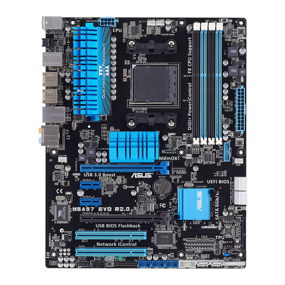
Page 20: Motherboard Overview
Motherboard overview 2.2.1 Motherboard layout Refer to 2.2.8 Internal connectors and 2.3.10 Rear panel connection for more information about rear panel connectors and internal connectors. Chapter 2: Hardware information... -
Page 21: Layout Contents
USB 2.0 connectors (10-1 pin USB910, USB1112, USB1314) 2-23 Standby power LED (SB_PWR) 2-20 IEEE 1394a port connector (10-1 pin IE1394_2) 2-24 Front panel audio connector (10-1 pin AAFP) 2-25 Digital audio connector (4-1 pin SPDIF_OUT) 2-24 ASUS M5A97 EVO... -
Page 22: Central Processing Unit (Cpu)
2.2.2 Central Processing Unit (CPU) The motherboard comes with an AM3+ socket designed for AMD FX / Phenom™ II / Athlon ® ™ II / Sempron™ 100 Series Processors. Ensure that all power cables are unplugged before installing the CPU. Chapter 2: Hardware information... -
Page 23: System Memory
The motherboard comes with four Double Data Rate 3 (DDR3) Dual Inline Memory Modules (DIMM) slots. A DDR3 module is notched differently from a DDR or DDR2 module. DO NOT install a DDR or DDR2 memory module to the DDR3 slot. Recommended memory configurations ASUS M5A97 EVO... -
Page 24: Memory Configurations
Always install DIMMs with the same CAS latency. For optimum compatibility, we recommend that you obtain memory modules from the same vendor. • Due to CPU spec., AMD 100 series CPUs support up to DDR3 1066MHz. With ASUS design, this motherboard can support up to DDR3 1333MHz. •... - Page 25 1 DIMM 2 DIMM 4 DIMM G.SKILL F3-14400CL6D-4GBFLS(XMP) 4GB(2 x 2GB) DS 6-8-6-24 1.65 • • • G.SKILL F3-14400CL9D-4GBRL(XMP) 4GB(2 x 2GB) DS 9-9-9-24 1.6 • • KINGSTON KHX1800C9D3T1K3/6GX(XMP) 6GB(3 x 2GB) DS 1.65 • • • ASUS M5A97 EVO...
- Page 26 M5A97 EVO Motherboard Qualified Vendors Lists (QVL) DDR3 2000 MHz capability for AMD AM3 CPU DIMM socket support Chip (Optional) Vendor Part No. Size Chip NO. Timing Voltage Brand 1 DIMM 2 DIMM 4 DIMM A-DATA AX3U2000GC4G9B(XMP) DS - 9-11-9-27 1.55~1.75 • Apacer 78.AAGD5.9KD(XMP) 6GB(3 x 2GB)
- Page 27 • • • 4GB ) KINGSTON KHX1600C7D3K2/4GX(XMP) 4GB ( 2x 1.65 • • • 2GB ) KINGSTON KHX1600C8D3K2/4GX(XMP) 4GB ( 2x 1.65 • • 2GB ) KINGSTON KHX1600C9D3K2/4GX(XMP) 4GB ( 2x 1.65 • • • 2GB ) ASUS M5A97 EVO...
- Page 28 M5A97 EVO Motherboard Qualified Vendors Lists (QVL) DDR3 1600 MHz capability for AMD AM3 CPU (continued) DIMM socket support (Optional) Vendor Part No. Size Chip Brand Chip NO. Timing Voltage 1 DIMM 2 DIMM 4 DIMM Kingston KHX1600C9D3LK2/4GX(XMP) 4GB ( 2x 1.65 •...
- Page 29 OCZ3RPR13332GK 2GB ( 2x SS - 6-6-6 1.75 • • 1GB ) OCZ3P1333LV3GK 3GB(3 x SS - 7-7-7 1.65 • • • 1GB) OCZ3G1333LV4GK 4GB ( 2x DS - 9-9-9 1.65 • • • 2GB ) ASUS M5A97 EVO 2-11...
- Page 30 M5A97 EVO Motherboard Qualified Vendors Lists (QVL) DDR3 1333 MHz capability for AMD AM3 CPU (continued) DIMM socket support (Optional) Vendor Part No. Size Chip Brand Chip NO. Timing Voltage DIMM DIMM DIMM OCZ3RPR13334GK 4GB ( 2x DS - 6-6-6 1.75 •...
- Page 31 4 DIMMs: Supports four (4) modules inserted into both the blue and black slots as two pairs of Dual-channel memory configuration. • When overclocking, some AMD CPU models may not support DDR3 1600 or higher frequency DIMMs. • Visit the ASUS website for the latest QVL. ASUS M5A97 EVO 2-13...
-
Page 32: Expansion Slots
2.2.4 Expansion slots Ensure to unplug the power cord before adding or removing expansion cards. Failure to do so may cause you physical injury and damage motherboard components. Slot No. Slot Description PCIe 2.0 x16_1 slot [blue] (at x16 mode) PCIe 2.0 x1_1 slot PCIe 2.0 x1_2 slot PCIe 2.0 x16_2 slot [black] (at x4 mode) - Page 33 – – – – – – PCIE x16_2 – – – – shared – – – PCIE x1_1 – – – shared – – – – PCIE x1_2 – – shared – – – – – ASUS M5A97 EVO 2-15...
-
Page 34: Jumper
2.2.5 Jumper Clear RTC RAM (CLRTC) This jumper allows you to clear the Real Time Clock (RTC) RAM in CMOS. You can clear the CMOS memory of date, time, and system setup parameters by erasing the CMOS RTC RAM data. The onboard button cell battery powers the RAM data in CMOS, which include system setup information such as system passwords. -
Page 35: Onboard Switches
BIOS default settings. A messgae will appear during POST reminding you that the BIOS has been restored to its default settings. • We recommend that you download and update to the latest BIOS version from the ASUS website at www.asus.com after using the MemOK! function. ASUS M5A97 EVO 2-17... - Page 36 TPU switch Turning this switch to Enable will automatically optimize the system for fast, yet stable clock speeds. For ensuring the system performance, turn the switch setting to Enable when the system is powered off. • The TPU LED (O2LED1) near the TPU switch lights when the switch setting is turned to Enable.
- Page 37 • You may change the EPU settings in the software application or BIOS setup program, and enable the EPU function at the same time. However, the system will use the last setting you have made. ASUS M5A97 EVO 2-19...
-
Page 38: Onboard Leds
2.2.7 Onboard LEDs POST State LEDs The POST State LEDs of CPU, DRAM, VGA card, and HDD indicate key components status during POST (Power-on Self Test). If an error is found , the LED next to the error device will continue lighting until the problem is solved. This user-friendly design provides an intuitional way to locate the root problem within a second. - Page 39 TPU LED The TPU LED lights when the TPU switch is turned to Enable. EPU LED The EPU LED lights when the EPU switch is turned to Enable. ASUS M5A97 EVO 2-21...
-
Page 40: Internal Connectors
2.2.8 Internal connectors SB950 Serial ATA 6.0 Gb/s connectors (7-pin SATA6G_1-6 [gray]) ® These connectors connect to Serial ATA 6.0 Gb/s hard disk drives via Serial ATA 6.0 Gb/s signal cables. If you installed Serial ATA hard disk drives, you can create a RAID 0, 1, 5, and 10 configuration through the onboard AMD ®... - Page 41 Never connect a 1394 cable to the USB connectors. Doing so will damage the motherboard! You can connect the front panel USB cable to the ASUS Q-Connector (USB, blue) first, and then install the Q-Connector (USB) to the USB connector onboard if your chassis supports front panel USB ports.
- Page 42 IEEE 1394a port connector (10-1 pin IE1394_2) This connector is for an IEEE 1394a port. Connect the IEEE 1394a module cable to this connector, then install the module to a slot opening at the back of the system chassis. Never connect a USB cable to the IEEE 1394a connector. Doing so will damage the motherboard! The IEEE 1394 bracket is purchased separately.
-
Page 43: Front Panel Audio Connector
The connector is for a serial (COM) port. Connect the serial port module cable to the connector, then install the module to a slot opening at the back of the system chassis. The serial port bracket (COM1) is purchased separately. ASUS M5A97 EVO 2-25... - Page 44 • The CPU_FAN connector supports the CPU fan of maximum 1A (12 W) fan power. • Only the CPU_FAN, CHA_FAN 1 and CHA_FAN 2 connectors support the ASUS FAN Xpert feature. • If you install two VGA cards, we recommend that you plug the rear chassis fan cable to the motherboard connector labeled CHA_FAN1 or CHA_FAN2 for better thermal environment.
- Page 45 1000W power or above to ensure the system stability. • If you are uncertain about the minimum power supply requirement for your system, refer to the Recommended Power Supply Wattage Calculator at http://support.asus. com/PowerSupplyCalculator/PSCalculator.aspx?SLanguage=en-us for details. ASUS M5A97 EVO 2-27...
-
Page 46: System Panel Connector
System panel connector (20-8 pin PANEL) This connector supports several chassis-mounted functions. • System power LED (2-pin PLED) This 2-pin connector is for the system power LED. Connect the chassis power LED cable to this connector. The system power LED lights up when you turn on the system power, and blinks when the system is in sleep mode. -
Page 47: Building Your Computer System
AMD AM3+ CPU AMD AM3+ compatible CPU Fan DIMM SATA hard disk drive SATA optical disc drive (optional) Graphics card (optional) The tools and components in the table above are not included in the motherboard package. ASUS M5A97 EVO 2-29... -
Page 48: Cpu Installation
2.3.2 CPU installation The AMD AM3+ socket is compatible with AMD AM3+ and AM3 processors. Ensure you use a CPU designed for the AM3+ socket. The CPU fits in only one correct orientation. DO NOT force the CPU into the socket to prevent bending the connectors on the socket and damaging the CPU! 2-30 Chapter 2: Hardware information... -
Page 49: Cpu Heatsink And Fan Assembly Installation
2.3.3 CPU heatsink and fan assembly installation Apply the Thermal Interface Material to the CPU heatsink and CPU before you install the heatsink and fan if necessary. ASUS M5A97 EVO 2-31... - Page 50 To install the CPU heatsink and fan assembly 2-32 Chapter 2: Hardware information...
- Page 51 ASUS M5A97 EVO 2-33...
-
Page 52: Dimm Installation
2.3.4 DIMM installation To remove a DIMM 2-34 Chapter 2: Hardware information... -
Page 53: Motherboard Installation
2.3.5 Motherboard installation The diagrams in this section are for reference only. The motherboard layout may vary with models, but the installation steps remain the same. ASUS M5A97 EVO 2-35... - Page 54 DO NOT overtighten the screws! Doing so can damage the motherboard. 2-36 Chapter 2: Hardware information...
-
Page 55: Atx Power Connection
2.3.6 ATX Power connection ASUS M5A97 EVO 2-37... -
Page 56: Sata Device Connection
2.3.7 SATA device connection 2-38 Chapter 2: Hardware information... -
Page 57: Front I/O Connector
2.3.8 Front I/O Connector To install ASUS Q-Connector To install USB 2.0 Connector To install front panel audio connector AAFP USB 2.0 To install USB 3.0 Connector USB 3.0 ASUS M5A97 EVO 2-39... -
Page 58: Expension Card Installation
2.3.9 Expension Card installation To install PCIe x16 cards To install PCIe x1 cards To install PCI cards 2-40 Chapter 2: Hardware information... -
Page 59: Rear Panel Connection
11. USB 2.0 ports 7 and 8 ® 6. USB 2.0 ports 1 and 2 12. Audio I/O ports** * and **: Refer to the tables on the next page for LAN port LED and audio port definitions. ASUS M5A97 EVO 2-41... - Page 60 • DO NOT insert a different connector to the external SATA port. • Due to USB 3.0 controller limitation, USB 3.0 devices can only be used under Windows ® OS environment and after the USB 3.0 driver installation. • USB 3.0 devices can only be used as data storage only. •...
-
Page 61: Audio I/O Connections
2.3.11 Audio I/O connections Audio I/O ports Connect to Headphone and Mic Connect to Stereo Speakers Connect to 2.1 channel Speakers ASUS M5A97 EVO 2-43... - Page 62 Connect to 4.1 channel Speakers Connect to 5.1 channel Speakers Connect to 7.1 channel Speakers When the DTS Surround Sensation UltraPC function is enabled, ensure to connect the rear speaker to the gray port. 2-44 Chapter 2: Hardware information...
-
Page 63: Starting Up For The First Time
While the system is ON, pressing the power switch for less than four seconds puts the system on sleep mode or soft-off mode, depending on the BIOS setting. Pressing the power switch for more than four seconds lets the system enter the soft-off mode regardless of the BIOS setting. ASUS M5A97 EVO 2-45... - Page 64 2-46 Chapter 2: Hardware information...
-
Page 65: Chapter 3: Bios Setup
BIOS setup Knowing BIOS The new ASUS UEFI BIOS is an Unified Extensible Firmware Interface, offering a user- friendly interface that goes beyond traditional keyboard-only BIOS controls to enable more flexible and convenient mouse input. Users can easily navigate the new UEFI BIOS with the same smoothness as their operating system. -
Page 66: Ez Mode
Default(F5) Selects the boot device priority Power Saving mode Loads optimized default Normal mode ASUS Optimal mode Displays the system properties of the selected mode on the right hand side Selects the boot device priority • The boot device options vary depending on the devices you installed to the system. -
Page 67: Advanced Mode
The Advanced Mode provides advanced options for experienced end-users to configure the BIOS settings. The figure below shows an example of the Advanced Mode. Refer to the following sections for the detailed configurations. To access the EZ Mode, click Exit, then select ASUS EZ Mode. Back button Menu items... -
Page 68: Menu Items
Menu items The highlighted item on the menu bar displays the specific items for that menu. For example, selecting Main shows the Main menu items. The other items (Ai Tweaker, Advanced, Monitor, Boot, Tool, and Exit) on the menu bar have their respective menu items. -
Page 69: Main Menu
RAM to clear the BIOS password. See section 2.2.5 Jumper for information on how to erase the RTC RAM. The Administrator or User Password items on top of the screen show the default • Not Installed. After you set a password, these items show Installed. ASUS M5A97 EVO... -
Page 70: Administrator Password
Administrator Password If you have set an administrator password, we recommend that you enter the administrator password for accessing the system. Otherwise, you might be able to see or change only selected fields in the BIOS setup program. To set an administrator password: Select the Administrator Password item and press <Enter>. -
Page 71: Ai Tweaker Menu
1.100V Auto CPU VDDA Voltage 2.500V Auto DRAM Voltage 1.550V Auto NB Voltage 1.100V Auto NB HT Voltage 1.200V Auto NB 1.8V Voltage 1.800V Auto SB Voltage 1.800V Auto Version 2.00.1201. Copyright (C) 2010 American Megatrends, Inc. ASUS M5A97 EVO... - Page 72 Ai Overclock Tuner [Auto] Allows you to select the CPU overclocking options to achieve the desired CPU internal frequency. Select any of these preset overclocking configuration options: [Auto] Loads the optimal settings for the system. [Manual] Allows you to individually set overclocking parameters. [D.O.C.P.] CPU Bus, CPU ratio and memory parameters will be auto optimized.
- Page 73 Configuration options: [Auto] [2 CLK] – [10 CLK] DRAM READ to READ Timing [Auto] Configuration options: [Auto] [2 CLK] – [10 CLK] DRAM Refresh Rate [Auto] Configuration options: [Auto] [Every 7.8ms] [Every 3.9ms] DRAM Command Rate [Auto] Configuration options: [Auto] [1T] [2T] ASUS M5A97 EVO...
- Page 74 DRAM Driving Control CKE drive strength [Auto] Configuration options: [Auto] [1x] [1.25x] [1.5x] [2x] CS/ODT drive strength [Auto] Configuration options: [Auto] [1x] [1.25x] [1.5x] [2x] ADDR/CMD drive strength [Auto] Configuration options: [Auto] [1x] [1.25x] [1.5x] [2x] MEMCLK drive strength [Auto] Configuration options: [Auto] [0.75x] [1x] [1.25x] [1.5x] Data drive strength [Auto] Configuration options: [Auto] [0.75x] [1x] [1.25x] [1.5x]...
- Page 75 Reducing phase number under light system loading to increase VRM efficiency [Standard] Proceeds phase control depending on the CPU loading. [Optimized] Loads the ASUS optimized phase tuning profile. [Extreme] Proceeds the full phase mode. [Manual Adjustment] Allows manual adjustment.
- Page 76 CPU/NB Offset Mode Sign [+] To offset the voltage by a positive value. [–] To offset the voltage by a negative value. CPU/NB Offset Voltage [Auto] This item appears only when you set the CPU & NB Voltage Mode item to [Offset] and allows you to set the CPU/NB Offset voltage.
-
Page 77: Advanced Menu
> APM →←: Select Screen ↑↓: Select Item Enter: Select +/-: Change Opt. F1: General Help F2: Previous Values F5: Optimized Defaults F10: Save ESC: Exit F12: Print Screen Version 2.00.1201. Copyright (C) 2010 American Megatrends, Inc. ASUS M5A97 EVO 3-13... -
Page 78: Cpu Configuration
3.5.1 CPU Configuration The items in this menu show the CPU-related information that the BIOS automatically detects. The items shown in this screen may be different due to the CPU you installed. UEFI BIOS Utility - Advanced Mode Exit Ai Tweaker Main Advanced Monitor... -
Page 79: North Bridge Configuration
Memory Hole Remapping [Enabled] Configuration options: [Disabled] [Enabled] DCT Unganged Mode [Enabled] Configuration options: [Disabled] [Enabled] Initiate Graphic Adapter [PEG/PCI] Allows you to decide which graphics controller to use as the primary boot device. Configuration options: [PCI/PEG] [PEG/PCI] ASUS M5A97 EVO 3-15... -
Page 80: Sata Configuration
3.5.3 SATA Configuration While entering Setup, the BIOS automatically detects the presence of SATA devices. The SATA Port items show Not Present if no SATA device is installed to the corresponding SATA port. UEFI BIOS Utility - Advanced Mode Exit Ai Tweaker Main Advanced... - Page 81 SATA Hot Plug on PORT3 [Disabled] Configuration options: [Enabled] [Disabled] SATA Hot Plug on PORT4 [Disabled] Configuration options: [Enabled] [Disabled] SATA Hot Plug on PORT5 [Disabled] Configuration options: [Enabled] [Disabled] SATA Hot Plug on PORT6 [Disabled] Configuration options: [Enabled] [Disabled] ASUS M5A97 EVO 3-17...
-
Page 82: Usb Configuration
3.5.4 USB Configuration The items in this menu allow you to change the USB-related features. UEFI BIOS Utility - Advanced Mode Exit Main Ai Tweaker Advanced Monitor Boot Tool Back Advanced\ USB Configuration > USB Configuration Enables Legacy USB support. AUTO option disables legacy support if no USB Devices: USB devices are connected. -
Page 83: Cpu Core On/Off Function
Auto System might become unstable due to different CPU margins. ASUS Core Unlocker [Disabled] [Enabled] Enables the ASUS Core Unlocker to get the full computing power of the processor. [Disabled] Disables this function. CPU Core Activation [Auto] This item lets user turn off core except core 1, user can turn off 2nd, 3rd, 4th, 5th, etc core manually. -
Page 84: Serial Port Configuration
JMB Storage Controller [Enabled] Allows you to enable or disable the JMB storage controller. Configuration options: [Disabled] [Enabled] If you want to use the full functin of the JMB storage contorller (ex. AHCI), we recommend that you set this item to [Enabled] and install the JMicron JMB36X Controller Driver from the motherboard support DVD. -
Page 85: Apm
Allows BIOS to switch off some power at S5 state to get system ready for the ErP requirement. When set to [Enabled], power for WOL, WO_USB, audio and onboard LEDs will be switched off at S5 state. ASUS M5A97 EVO 3-21... -
Page 86: Monitor Menu
Monitor menu The Monitor menu displays the system temperature/power status, and allows you to change the fan settings. UEFI BIOS Utility - Advanced Mode Exit Main Ai Tweaker Advanced Monitor Boot Tool CPU Temperature +69ºC / +181ºF +69ºC / +181ºF MB Temperature +35ºC / +120ºF VCORE Voltage... - Page 87 CPU fan warning speed. Configuration options: [Ignore] [200 RPM] [300 RPM] [400 RPM] [500 RPM] [600 RPM] Chassis Q-Fan Control [Disabled] [Disabled] Disables the Chassis Q-Fan control feature. [Enabled] Enables the Chassis Q-Fan control feature. ASUS M5A97 EVO 3-23...
-
Page 88: Boot Menu
[Disabled] Disables the full screen logo display feature. Set this item to [Enabled] to use the ASUS MyLogo 2™ feature. Wait for ‘F1’ If Error [Enabled] When set to [Enabled], the system waits for the F1 key to be pressed when error occurs. -
Page 89: Tools Menu
> ASUS O.C. Profile 3.8.1 ASUS EZ Flash 2 Allows you to run ASUS EZ Flash 2. When you press <Enter>, a confirmation message appears. Use the left/right arrow key to select between [Yes] or [No], then press <Enter> to confirm your choice. -
Page 90: Asus Spd Information
UEFI BIOS Utility - Advanced Mode Exit Ai Tweaker Main Advanced Monitor Boot Tool Back Tool\ ASUS SPD Information > DIMM Slot number DIMM Slot # Slot 2 Manufacturer Micron Module Size 2048 MBytes Maximum Bandwidth 1333 Mhz Part Number... -
Page 91: Asus O.c. Profile
Exit Ai Tweaker Main Advanced Monitor Boot Tool Back Tool\ ASUS O.C. Profile > O.C. Profile Configuration Save BIOS settings to Profile Setup Profile1 Status : Not Installed Setup Profile2 Status : Not Installed Setup Profile3 Status : Not Installed... -
Page 92: Exit Menu
Load Optimized Defaults Save Changes & Reset Discard Changes & Exit ASUS EZ Mode Launch EFI Shell from filesystem device Load Optimized Defaults This option allows you to load the default values for each of the parameters on the Setup menus. -
Page 93: Updating Bios
BIOS in the future. Copy the original motherboard BIOS using the ASUS Update or BIOS Updater utilities. 3.10.1 ASUS Update utility The ASUS Update is a utility that allows you to manage, save, and update the motherboard BIOS in Windows environment. The ASUS Update utility allows you to: ®... - Page 94 To update the BIOS through the Internet: From the ASUS Update screen, select Update BIOS from Internet, and then click Next. Select the ASUS FTP site nearest you to avoid network traffic. If you want to enable the BIOS downgradable function and auto BIOS backup function, check the checkboxs before the two items on the screen.
- Page 95 The screenshots in this section are for reference only. The actual BIOS information vary by models. • Refer to the software manual in the support DVD or visit the ASUS website at www.asus.com for detailed software configuration. ASUS M5A97 EVO...
-
Page 96: Asus Ez Flash 2 Utility
3.10.2 ASUS EZ Flash 2 utility The ASUS EZ Flash 2 feature allows you to update the BIOS without having to use a bootable floppy disk or an OS-based utility. Before you start using this utility, download the latest BIOS from the ASUS website at www.asus.com. - Page 97 DO NOT shut down or reset the system while updating the BIOS to prevent system boot failure! Ensure to load the BIOS default settings to ensure system compatibility and stability. Select the Load Optimized Defaults item under the Exit menu. See section 3.9 Exit Menu for details. ASUS M5A97 EVO 3-33...
-
Page 98: Asus Bios Updater
3.10.3 ASUS BIOS Updater The ASUS BIOS Updater allows you to update BIOS in DOS environment. This utility also allows you to copy the current BIOS file that you can use as a backup when the BIOS fails or gets corrupted during the updating process. - Page 99 ASUSTek BIOS Updater for DOS V1.18 [2010/04/29] Current ROM Update ROM BOARD: M5A97 EVO BOARD: Unknown VER: 0204 VER: Unknown DATE: 08/05/2010 DATE: Unknown PATH: BIOS backup is done! Press any key to continue. Note Saving BIOS: ASUS M5A97 EVO 3-35...
- Page 100 Updating the BIOS file To update the BIOS file using BIOS Updater At the FreeDOS prompt, type bupdater /pc /g and press <Enter>. D:\>bupdater /pc /g The BIOS Updater screen appears as below. ASUSTek BIOS Updater for DOS V1.18 [2010/04/29] Current ROM Update ROM BOARD:...
-
Page 101: Chapter 4: Software Support
The contents of the support DVD are subject to change at any time without notice. Visit the ASUS website at www.asus.com for updates. 4.2.1 Running the support DVD Place the support DVD into the optical drive. -
Page 102: Obtaining The Software Manuals
The software manual files are in Portable Document Format (PDF). Install the Adobe ® Acrobat Reader from the Utilities menu before opening the files. ® Click the Manual tab. Click ASUS Motherboard Utility Guide from the manual list on the left. The Manual folder of the support DVD appears. Double-click the folder of your selected software. -
Page 103: Software Information
4.3.1 AI Suite II AI Suite II is an all-in-one interface that integrates several ASUS utilities and allows users to launch and operate these utilities simultaneously. Installing AI Suite II To install AI Suite II on your computer Place the support DVD to the optical drive. -
Page 104: Digi+ Vrm
4.3.2 DIGI+ VRM ASUS DIGI+ VRM allows you to adjust VRM voltage and frequency modulation to enhance reliability and stability. It also provides the highest power efficiency, generating less heat to longer component lifespan and minimize power loss. After installing AI Suite II from the motherboard support DVD, launch DIGI+ VRM by clicking Tool >... -
Page 105: Turbov Evo
4.3.3 TurboV EVO ASUS TurboV EVO introduces TurboV that allows you to manually adjust the CPU frequency and related voltages as well as Auto Tuning function that offers automatic and easy overlocking and system level up. After installing AI Suite II from the motherboard support DVD, launch TurboV EVO by clicking Tool >... -
Page 106: Cpu Ratio
Using Advanced Mode Click More Settings, and then click the Advanced Mode tab to adjust the advanced voltage settings. Advanced mode Voltage Target values Adjustment bars Undoes all changes Current values without applying Applies all changes Click to restore immediately all start-up settings CPU Ratio... - Page 107 Auto Tuning ASUS TurboV EVO includes two auto tuning modes, providing the most flexible auto-tuning options. • The overclocking result varies with the CPU model and the system configuration. • To prevent overheating from damaging the motherboard, a better thermal environment is strongly recommended.
- Page 108 TurboV automatically overclocks the CPU and memory and restarts the system. After re-entering Windows, a message appears indicating the current overclocking result. To keep the result, click Stop. If you did not click Stop in the previous step, TurboV automatically starts further system overclocking and stability test.
-
Page 109: Epu
Select From EPU Installation to show the CO2 that has been reduced since you *• installed EPU. *• Select From the Last Reset to show the total CO2 that has been reduced since you click the Clear button ASUS M5A97 EVO... -
Page 110: Fan Xpert
4.3.5 FAN Xpert Fan Xpert intelligently allows you to adjust both the CPU and chassis fan speeds according to different ambient temperatures caused by different climate conditions in different geographic regions and your PC’s system loading. The built-in variety of useful profiles offer flexible controls of fan speed to achieve a quiet and cool environment. -
Page 111: Probe Ii
The Preference tab allows you to customize the time interval of sensor alerts, or change the temperature unit. Saves your configuration Loads your saved Loads the default Applies your configuration threshold values for changes each sensor ASUS M5A97 EVO 4-11... -
Page 112: Sensor Recorder
4.3.7 Sensor Recorder Sensor Recorder allows you to monitor the changes in the system voltage, temperature, and fan speed, as well as recording the changes. Launching Sensor Recorder After installing AI Suite II from the motherboard support DVD, click Tool > Sensor Recorder on the AI Suite II main menu bar to launch Sensor Recorder. -
Page 113: Ai Charger
* Check your USB device manufacturer if it fully supports the BC 1.1 function. • ** The actual charging speed may vary with your USB device’s conditions. • Ensure to remove and reconnect your USB device after enabling or disabling Ai Charger+ to ensure normal charging function. ASUS M5A97 EVO 4-13... -
Page 114: Monitor
4.3.9 Monitor The Monitor section includes the Sensor and CPU Frequency panels. Sensor The Sensor panel displays the current value of a system sensor such as fan rotation, CPU temperature, and voltages. Click Monitor > Sensor on the AI Suite II main menu bar to launch the Sensor panel. -
Page 115: System Information
Click the CPU tab to see the details on • the processor and the Cache. Click the SPD tab and then select • the memory slot to see the details on the memory module installed on the corresponding slot. ASUS M5A97 EVO 4-15... -
Page 116: Audio Configurations
Realtek HD Audio Manager for Windows XP Exit button Configuration options Minimize button Control settings window Information button Refer to the software manual in the support DVD or visit the ASUS website at www.asus.com for detailed software configuration. 4-16 Chapter 4: Software support... -
Page 117: Raid Configurations
With the RAID 10 configuration you get all the benefits of both RAID 0 and RAID 1 configurations. Use four new hard disk drives or use an existing drive and three new drives for this setup. ASUS M5A97 EVO 4-17... -
Page 118: Installing Serial Ata Hard Disks
4.4.2 Installing Serial ATA hard disks The motherboard supports Serial ATA hard disk drives. For optimal performance, install identical drives of the same model and capacity when creating a disk array. To install the SATA hard disks for a RAID configuration: Install the SATA hard disks into the drive bays. -
Page 119: Amd ® Option Rom Utility
The RAID BIOS setup screens shown in this section are for reference only, and may not exactly match the items on your screen. To create a RAID volume using more than four hard disk drives, ensure that the SATA connectors 5/6 are set to [RAID] mode. ASUS M5A97 EVO 4-19... -
Page 120: Creating A Raid Volume
Creating a RAID volume To create a RAID volume: In the Main Menu, press <2> to enter the LD View / LD Define Menu function. Press <Ctrl> + <C>, and the following screen appears. Option ROM Utility (c) 2009 Advanced Micro Devices, Inc. [ LD Define Menu ] LD No LD Name... -
Page 121: Deleting A Raid Configuration
LD Name RAID Mode Capacity(GB) xxxxx RAID 0 157.99 Strip Block 64 KB Cache Mode WriteThru [ Drives Assignments ] Port:ID Drive Model Capabilities Capacity(GB) 01:00 xxxxxxxxx xxxxxxx xxxxxx 02:00 xxxxxxxxx xxxxxxx xxxxxx Any Key To Continue..ASUS M5A97 EVO 4-21... -
Page 122: Creating A Raid Driver Disk
Creating a RAID driver disk A floppy disk with the RAID driver is required when installing Windows XP operating system ® on a hard disk drive that is included in a RAID set. For Windows Vista or later operating ® systems, use either a USB flash drive with the RAID driver or the support DVD. -
Page 123: Installing The Raid Driver During Windows ® Os Installation
Follow the succeeding screen instructions to complete the installation. Before loading the RAID driver from a USB flash drive, you have to use another computer to copy the RAID driver from the support DVD to the USB flash drive. ASUS M5A97 EVO 4-23... -
Page 124: Using A Usb Floppy Disk Drive
4.5.4 Using a USB floppy disk drive Due to OS limitation, Windows XP may not recognize the USB floppy disk drive when you ® install the RAID driver from a floppy disk during the OS installation. To solve this issue, add the USB floppy disk drive’s Vendor ID (VID) and Product ID (PID) to the floppy disk containing the RAID driver. - Page 125 “PCI\VEN_1002&DEV_4391&CC_0106”,”ahcix86” id= “PCI\VEN_1002&DEV_4393&CC_0104”,”ahcix86” id= “USB\VID_03EE&PID_6901”, “usbstor” [HardwareIds.SCSI.Napa_amd64_ahci] id= “PCI\VEN_1002&DEV_4392&CC_0104”,”ahcix64” id= “PCI\VEN_1002&DEV_4391&CC_0106”,”ahcix64” id= “PCI\VEN_1002&DEV_4393&CC_0104”,”ahcix64” id= “USB\VID_03EE&PID_6901”, “usbstor” Add the same line to both sections. The VID and PID vary with different vendors. Save and exit the file. ASUS M5A97 EVO 4-25...
- Page 126 4-26 Chapter 4: Software support...
-
Page 127: Multiple Gpu Technology Support
For Windows XP, go to Control Panel > Add/Remove Programs. For Windows Vista, go to Control Panel > Programs and Features. Select your current graphics card driver/s. For Windows XP, select Add/Remove. For Windows Vista, select Uninstall. Turn off your computer. ASUS M5A97 EVO... -
Page 128: Installing Two Crossfirex™ Graphics Cards
5.1.3 Installing two CrossFireX™ graphics cards The following pictures are for reference only. The graphics cards and the motherboard layout may vary with models, but the installation steps remain the same. Prepare two CrossFireX-ready graphics cards. Insert the two graphics card into the PCIEX16 slots. -
Page 129: Installing The Device Drivers
In the Catalyst Control Center window, click Graphics Settings > CrossFireX > Configure. From the Graphics Adapter list, select the graphics card to act as the display GPU. Select Enable CrossFireX. Click Apply, and then click OK to exit the window. ASUS M5A97 EVO... - Page 130 Chapter 5: ATI CrossFireX™ technology support ®...
-
Page 131: Asus Contact Information
+1-812-282-3777 +1-510-608-4555 Web site usa.asus.com Technical Support Telephone +1-812-282-2787 Support fax +1-812-284-0883 Online support support.asus.com ASUS COMPUTER GmbH (Germany and Austria) Address Harkort Str. 21-23, D-40880 Ratingen, Germany +49-2102-959911 Web site www.asus.de Online contact www.asus.de/sales Technical Support Telephone +49-1805-010923* Support Fax...