Table of Contents
Advertisement
Advertisement
Table of Contents

Related Manuals for Asus M4A77TD - Motherboard - ATX


Summary of Contents for Asus M4A77TD - Motherboard - ATX
- Page 1 M4A77TD...
- Page 2 Product warranty or service will not be extended if: (1) the product is repaired, modified or altered, unless such repair, modification of alteration is authorized in writing by ASUS; or (2) the serial number of the product is defaced or missing.
-
Page 3: Table Of Contents
Welcome! ..................1-1 Package contents ................. 1-1 Special features ................1-1 1.3.1 Product highlights ............1-1 1.3.2 Innovative ASUS features ..........1-3 Before you proceed ..............1-5 Motherboard overview ..............1-6 1.5.1 Placement direction ............1-6 1.5.2 Screw holes ..............1-6 1.5.3... - Page 4 Chapter 2: BIOS information Managing and updating your BIOS ..........2-1 2.1.1 ASUS Update utility ............2-1 2.1.2 ASUS EZ Flash 2 utility ........... 2-3 2.1.3 ASUS CrashFree BIOS utility ......... 2-4 BIOS setup program ..............2-5 2.2.1 BIOS menu screen ............2-6 2.2.2...
- Page 5 Boot Device Priority ............2-19 2.6.2 Boot Settings Configuration .......... 2-20 2.6.3 Security ................. 2-21 Tools menu ................. 2-22 2.7.1 ASUS EZ Flash 2 ............2-23 2.7.2 Express Gate ..............2-23 2.7.3 AI NET 2................ 2-23 Exit menu ..................2-24...
-
Page 6: Notices
Complying with the REACH (Registration, Evaluation, Authorisation, and Restriction of Chemicals) regulatory framework, we published the chemical substances in our products at ASUS REACH website at http://green.asus.com/english/REACH.htm. DO NOT throw the motherboard in municipal waste. This product has been designed to enable proper reuse of parts and recycling. -
Page 7: Safety Information
Safety information Electrical safety • To prevent electric shock hazard, disconnect the power cable from the electric outlet before relocating the system. • When adding or removing devices to or from the system, ensure that the power cables for the devices are unplugged before the signal cables are connected. If possible, disconnect all power cables from the existing system before you add a device. -
Page 8: About This Guide
Operation safety • Before installing the motherboard and adding devices on it, carefully read all the manuals that came with the package. • Before using the product, ensure that all cables are correctly connected and the power cables are not damaged. If you detect any damage, contact your dealer immediately. •... -
Page 9: Conventions Used In This Guide
Refer to the following sources for additional information and for product and software updates. ASUS websites The ASUS website provides updated information on ASUS hardware and software products. Refer to the ASUS contact information. Optional documentation Your product package may include optional documentation, such as warranty flyers, that may have been added by your dealer. -
Page 10: M4A77Td Specifications Summary
4 x 240-pin DIMM slots support maximum 16GB unbuffered ECC and non-ECC DDR3 1800(O.C.) / 1600(O.C.) / 1333 / 1066MHz memory modules * Refer to www.asus.com for the latest Memory QVL (Qualified Vendors List). ** When you install a total memory of 4GB or more,... - Page 11 – FSB tuning from 200MHz to 550MHz at 1MHz increment – PCIe frequency tuning from 100MHz to 150MHz at 1MHz increment ASUS C.P.R. (CPU Parameter Recall) Accessories 2 x Serial ATA cables 1 x Ultra DMA 133/100/66 cable 1 x I/O shield...
-
Page 13: Chapter 1: Product Introduction
® The motherboard delivers a host of new features and latest technologies, making it another standout in the long line of ASUS quality motherboards! Before you start installing the motherboard, and hardware devices on it, check the items in your package with the list below. - Page 14 770 Chipset ® The AMD 770 Chipset is designed to support up to 5200MT/s ® HyperTransport™ 3.0 (HT 3.0) interface speed and PCI Express 2.0 x16 graphics. It is optimized with AMD’s latest AM3 multi-core CPUs to provide excellent system performance and overclocking capabilities. HyperTransport™...
-
Page 15: Innovative Asus Features
USB port before turning on the computer. • The actual boot time depends on the system configuration. • ASUS Express Gate supports file uploading from SATA HDDs, ODDs and USB drives. It supports file downloading to USB drives only. -
Page 16: Asus Mylogo2
BIOS file using the bundled support DVD or a USB flash disk that contains the BIOS file. ASUS EZ Flash 2 ASUS EZ Flash 2 allows you to update the BIOS from a USB flash disk before entering the OS. ASUS Q-Fan... -
Page 17: Before You Proceed
ON, in sleep mode, or in soft-off mode. This is a reminder that you should shut down the system and unplug the power cable before removing or plugging in any motherboard component. The illustration below shows the location of the onboard LED. SB_PWR M4A77TD Standby Power Powered Off M4A77TD Onboard power LED ASUS M4A77TD... -
Page 18: Motherboard Overview
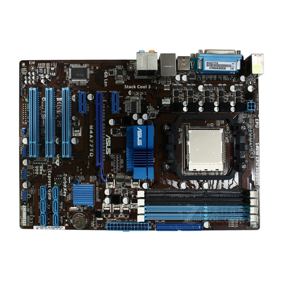
Motherboard overview 1.5.1 Placement direction When installing the motherboard, ensure that you place it into the chassis in the correct orientation. The edge with external ports goes to the rear part of the chassis as indicated in the image below. 1.5.2 Screw holes Place six screws into the holes indicated by circles to secure the motherboard to the chassis. -
Page 19: Motherboard Layout
10. Onboard power LED (SB_PWR) IDE connector (40-1 pin PRI_IDE) 1-22 11. Digital audio connector (4-1 pin SPDIF_OUT) 1-26 SATA connectors (7-pin SATA1, SATA2, SATA3, SATA4, 1-23 12. Front panel audio connector (10-1 pin AAFP) 1-26 SATA5, and SATA6) ASUS M4A77TD... -
Page 20: Central Processing Unit (Cpu)
Central Processing Unit (CPU) This motherboard comes with an AM3 socket designed for Phenom™ II / Athlon™ II / Sempron™ 100 series processors. The AM3 socket has a different pinout from the AM2+/AM2 socket. Ensure that you use a CPU designed for the AM3 socket. The CPU fits in only one correct orientation. DO NOT force the CPU into the socket to prevent bending the pins and damaging the CPU! 1.6.1 Installing the CPU... - Page 21 Connect the CPU fan cable to the CPU_FAN connector on the motherboard. CPU_FAN CPU FAN PWR CPU FAN IN CPU FAN PWM M4A77TD M4A77TD CPU fan connector DO NOT forget to connect the CPU fan connector! Hardware monitoring errors can occur if you fail to plug this connector. ASUS M4A77TD...
-
Page 22: Installing The Heatsink And Fan
1.6.2 Installing the heatsink and fan Ensure that you use only AMD-certified heatsink and fan assembly. To install the CPU heatsink and fan: Place the heatsink on top of the installed CPU, ensuring that the heatsink fits properly on the retention module base. •... -
Page 23: System Memory
DDR2 DIMM socket. DDR3 modules are developed for better performance with less power consumption. The figure illustrates the location of the DDR3 DIMM sockets: Channel Sockets Channel A DIMM_A1 and DIMM_A2 Channel B DIMM_B1 and DIMM_B2 M4A77TD M4A77TD 240-pin DDR3 DIMM sockets ASUS M4A77TD 1-11... -
Page 24: Memory Configurations
1.7.2 Memory configurations You may install 512MB, 1GB, 2GB, and 4GB unbuffered ECC and non-ECC DDR3 DIMMs into the DIMM sockets. • You may install varying memory sizes in Channel A and Channel B. The system maps the total size of the lower-sized channel for the dual-channel configuration. Any excess memory from the higher-sized channel is then mapped for single-channel operation. - Page 25 • 3072MB(Kit G.SkiLL F3-10666CL7T-3GBPK Heat-Sink Package 7-7-7-18 • • • of 3) 3072MB(Kit G.SkiLL F3-10666CL9T-3GBNQ Heat-Sink Package 9-9-9-24 • • • of 3) G.SKILL F3-10600CL7D-2GBPI 1024MB G.SKILL Heat-Sink Package • • • (continued on the next page) ASUS M4A77TD 1-13...
- Page 26 DDR3-1333MHz capability DIMM support Vendor Part No. Size Chip Brand Chip NO. G.SKILL F3-10600CL9D-2GBNQ 1024MB G.SKILL Heat-Sink Package • • • G.SKILL F3-10666CL9D-4GBPK 2048MB G.SKILL Heat-Sink Package • • • 6144MB(Kit G.SkiLL F3-10666CL7T-6GBPK Heat-Sink Package 7-7-7-18 • • • of 3 ) 6144MB(Kit G.SKILL F3-1066CL9T-6GBNQ...
- Page 27 • C*: Supports two pairs of modules inserted into both the blue slots and the black slots as two pairs of dual-channel memory configuration. Visit the ASUS website at www.asus.com for the latest QVL. ASUS M4A77TD 1-15...
-
Page 28: Installing A Dimm
1.7.3 Installing a DIMM Unplug the power supply before adding or removing DIMMs or other system components. Failure to do so can cause severe damage to both the motherboard and the components. Press the retaining clips outward to DIMM notch unlock a DIMM socket. -
Page 29: Expansion Slots
This motherboard supports PCI Express x1 network cards, SCSI cards, and other cards that comply with the PCI Express specifications. 1.8.5 PCI Express x16 slot This motherboard supports a PCI Express x16 graphics card that comply with the PCI Express specifications. ASUS M4A77TD 1-17... -
Page 30: Jumpers
Jumpers Clear RTC RAM (CLRTC) This jumper allows you to clear the Real Time Clock (RTC) RAM in CMOS. You can clear the CMOS memory of date, time, and system setup parameters by erasing the CMOS RTC RAM data. The onboard button cell battery powers the RAM data in CMOS, which include system setup information such as system passwords. -
Page 31: Connectors
Side Speaker Out port (gray). This port connects to the side speakers in the 8-channel audio configuration. Refer to the audio configuration table on the next page for the function of the audio ports in the 2, 4, 6, or 8-channel configuration. ASUS M4A77TD 1-19... - Page 32 Audio 2, 4, 6, or 8-channel configuration Headset Port 4-channel 6-channel 8-channel 2-channel Light Blue Line In Line In Line In Line In Lime Line Out Front Speaker Out Front Speaker Out Front Speaker Out Pink Mic In Mic In Mic In Mic In Orange...
-
Page 33: Internal Connectors
The system may become unstable or may not boot up if the power is inadequate. • If you are uncertain about the minimum power supply requirement for your system, refer to the Recommended Power Supply Wattage Calculator at http://support.asus. com/PowerSupplyCalculator/PSCalculator.aspx?SLanguage=en-us for details. ASUS M4A77TD... - Page 34 IDE connector (40-1 pin PRI_IDE) The onboard IDE connector is for Ultra DMA 133/100/66 signal cable. There are three connectors on each Ultra DMA 133/100/66 signal cable: blue, black, and gray. Connect the blue connector to the motherboard’s IDE connector, then select one of the following modes to configure your devices: Drive jumper setting Mode of device(s)
- Page 35 XP limitation, Windows XP may not recognize the USB floppy disk ® ® drive. • For more details on RAID/AHCI, refer to the RA ID/AHCI Supplementary Guide included in the folder named Manual in the support DVD. ASUS M4A77TD 1-23...
-
Page 36: System Panel Connector
System panel connector (20-8 pin PANEL) This connector supports several chassis-mounted functions. PLED SPEAKER PANEL PIN 1 M4A77TD IDE_LED PWRSW RESET * Requires an ATX power supply M4A77TD System panel connector • System power LED This 2-pin connector is for the system power LED. Connect the chassis power LED cable to this connector. - Page 37 480Mbps connection speed. USB78 USB1112 USB910 M4A77TD PIN 1 PIN 1 PIN 1 M4A77TD USB2.0 connectors Never connect a 1394 cable to the USB connectors. Doing so will damage the motherboard! The USB 2.0 module is purchased separately. ASUS M4A77TD 1-25...
-
Page 38: Front Panel Audio Connector
Digital audio connector (4-1 pin SPDIF_OUT) This connector is for an additional Sony/Philips Digital Interface (S/PDIF) port. M4A77TD SPDIF_OUT M4A77TD Digital audio connector Ensure that the audio device of Sound playback is VIA High Definition Audio (the name may be different based on the OS). Go to Start > Control Panel > Sounds and Audio Devices >... - Page 39 DO NOT forget to connect the fan cables to the fan connectors. Insufficient air flow inside the system may damage the motherboard components. These are not jumpers! DO NOT place jumper caps on the fan connectors. Only the 4-pin CPU fan supports the ASUS Q-Fan feature. ASUS M4A77TD 1-27...
-
Page 40: Software Support
The contents of the Support DVD are subject to change at any time without notice. Visit the ASUS website at www.asus.com for updates. To run the Support DVD Place the Support DVD into the optical drive. -
Page 41: Chapter 2: Bios Information
BIOS in the future. Copy the original motherboard BIOS using the ASUS Update utility. 2.1.1 ASUS Update utility The ASUS Update is a utility that allows you to manage, save, and update the motherboard BIOS in Windows environment. ®... -
Page 42: Updating The Bios
Updating from the Internet Select Update BIOS from the Internet, then click Next. Select the ASUS FTP site nearest you to avoid network traffic, or click Auto Select then click Next. From the FTP site, select the BIOS version that you want to download then click Next. -
Page 43: Asus Ez Flash 2 Utility
2.1.2 ASUS EZ Flash 2 utility The ASUS EZ Flash 2 feature allows you to update the BIOS without using an OS-based utility. Before you start using this utility, download the latest BIOS file from the ASUS website at www.asus.com. -
Page 44: Asus Crashfree Bios Utility
2.1.3 ASUS CrashFree BIOS utility The ASUS CrashFree BIOS is an auto recovery tool that allows you to restore the BIOS file when it fails or gets corrupted during the updating process. You can restore a corrupted BIOS file using the motherboard support DVD or a removable device that contains the updated BIOS file. -
Page 45: Bios Setup Program
• The BIOS setup screens in this chapter are for reference only. They may not exactly match what you see on your screen. • Visit the ASUS website at www.asus.com to download the latest BIOS file for this motherboard. ASUS M4A77TD... -
Page 46: Bios Menu Screen
2.2.1 BIOS menu screen Menu items Menu bar Configuration fields General help BIOS SETUP UTILITY Main Advanced Power Boot Tools Exit Main Settings Use [ENTER], [TAB] System Time [19:34:30] or [SHIFT-TAB] to System Date [Fri 07/31/2009] select a field. Primary IDE Master :[Not Detected] Use [+] or [-] to Primary IDE Slave... -
Page 47: Menu Items
Press the <Up> / <Down> arrow keys or <Page Up> /<Page Down> keys to display the other items on the screen. 2.2.9 General help At the top right corner of the menu screen is a brief description of the selected item. ASUS M4A77TD... -
Page 48: Main Menu
Main menu When you enter the BIOS Setup program, the Main menu screen appears, giving you an overview of the basic system information. Refer to section 2.2.1 BIOS menu screen for information on the menu screen items and how to navigate through them. BIOS SETUP UTILITY Main Advanced... -
Page 49: Sata Configuration
OS. Ensure to install the AHCI driver, so that you can use SATA 1/2/3/4/5/6 in AHCI mode under OS. • When SATA 1/2/3/4 are configured as [AHCI] and SATA 5/6 are configured as [IDE], you can access the devices on SATA 5/6 before entering OS. ASUS M4A77TD... -
Page 50: System Information
2.3.5 System Information This menu gives you an overview of the general system specifications. The BIOS automatically detects the items in this menu. BIOS Information Displays the auto-detected BIOS information. Processor Displays the auto-detected CPU specification. System Memory Displays the auto-detected system memory. Advanced menu The Advanced menu items allow you to change the settings for the CPU and other system devices. - Page 51 HT Over Voltage [Auto] Sets the HT over voltage. The values range from 1.25000V to 1.38500V with a 0.01500V increment. Use the <+> / <-> keys to adjust the value. Configuration options: [Auto] [Max. = 1.38500V] [Min. = 1.25000V] ASUS M4A77TD 2-11...
- Page 52 DRAM Frequency [Auto] Selects the DRAM frequency programming method. If this item is set to [Auto], the DRAM speed depends on the SPDs. Configuration options: [Auto] [800MHz] [1067MHz] [1333MHz] [1600MHz] Memory Over Voltage [Auto] Sets the memory over voltage. The values range from 1.5000V to 2.2050V with a 0.0150V increment.
-
Page 53: Cpu Configuration
Enables or disables Secure Virtual Machine Mode (SVM). Configuration options: [Disabled] [Enabled] Cool ‘n’ Quiet [Enabled] Enables or disables the AMD Cool ‘n’ Quiet technology. Configuration options: [Enabled] ® [Disabled] ACPI SRAT Table [Enabled] Enables or disables the building of ACPI SRAT table. Configuration options: [Enabled] [Disabled] ASUS M4A77TD 2-13... -
Page 54: Chipset
C1E Configuration [Disabled] Enables or disables the CPU Enhanced Halt (C1E) function, a CPU power-saving function in system halt state. When this item is enabled, the CPU core frequency and voltage will be reduced during the system halt state to decrease power consumption. Configuration options: [Disabled] [Enabled] Advanced Clock Calibration [Disabled] Adjusts the processor’s overclocking capability. -
Page 55: Onboard Device Configuration
When this item is set to [No], BIOS configures all the devices in the system. When this item is set to [Yes] and if you install a Plug and Play operating system, the operating system configures the Plug and Play devices not required for boot. Configuration options: [No] [Yes] ASUS M4A77TD 2-15... -
Page 56: Usb Configuration
2.4.6 USB Configuration The items in this menu allows you to change the USB-related features. Select an item then press <Enter> to display the configuration options. The Module Version and USB Devices Enabled items show the auto-detected values. If no USB device is detected, the item shows None. -
Page 57: Power Menu
Power on From S5 By PME# [Disabled] Enables or disables PME wake from sleep states. Configuration options: [Disabled] [Enabled] Power on From S5 By Ring [Disabled] Enables or disables ring to generate a wake event. Configuration options: [Disabled] [Enabled] ASUS M4A77TD 2-17... -
Page 58: Hw Monitor Configuration
The onboard hardware monitor automatically detects the voltage output through the onboard voltage regulators. Smart Q-Fan Function [Enabled] Enables or disables the ASUS Q-Fan feature that smartly adjusts the CPU fan speeds for more efficient system operation. Configuration options: [Disabled] [Enabled] Fan Auto Mode Start Voltage [5.0V] Selects the fan auto mode start voltage. -
Page 59: Boot Menu
Configuration options: [Removable Dev.] [Hard Drive] [ATAPI CD-ROM] [Disabled] • To select the boot device during system startup, press <F8> when ASUS logo appears. • To access Windows OS in Safe Mode, do any of the following: •... -
Page 60: Boot Settings Configuration
Enables or disables the full screen logo display feature. Configuration options: [Disabled] [Enabled] Set this item to [Enabled] to use the ASUS MyLogo2™ feature. AddOn ROM Display Mode [Force BIOS] Sets the display mode for option ROM. Configuration options: [Force BIOS] [Keep Current] Bootup Num-Lock [On] Selects the power-on state for the NumLock. -
Page 61: Security
View Only allows access but does not allow change to any field. Limited allows changes only to selected fields, such as Date and Time. Full Access allows viewing and changing all the fields in the Setup utility. ASUS M4A77TD 2-21... -
Page 62: Tools Menu
<Enter> to display the sub-menu. BIOS SETUP UTILITY Main Advanced Power Boot Tools Exit Press ENTER to run ASUS EZ Flash 2 the utility to select and update BIOS. This utility supports: Express Gate [Auto] 1.FAT 12/16/32 (r/w) Enter OS Timer [10 Seconds] 2.NTFS (read only) -
Page 63: Asus Ez Flash 2
2.7.1 ASUS EZ Flash 2 Allows you to run ASUS EZ Flash 2. When you press <Enter>, a confirmation message appears. Use the left/right arrow key to select between [Yes] or [No], then press <Enter> to confirm your choice. 2.7.2 Express Gate [Auto] Allows you to enable or disable the ASUS Express Gate feature. -
Page 64: Exit Menu
Exit menu The Exit menu items allow you to load the optimal or failsafe default values for the BIOS items, and save or discard your changes to the BIOS items. BIOS SETUP UTILITY Main Advanced Power Boot Tools Exit Exit Options Exit system setup after saving the Exit &...