Panasonic AW-PH300 Operating Instructions Manual
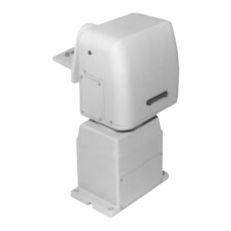
Indoor pan/tilt head
Hide thumbs
Also See for AW-PH300:
- Operating instructions manual (24 pages) ,
- Operating instructions manual (24 pages)

Related Manuals for Panasonic AW-PH300


Summary of Contents for Panasonic AW-PH300
- Page 1 Indoor Pan/Tilt Head AW-PH300 Before attempting to connect or operate this product, please read these instructions completely.
- Page 2 CAUTION For U.S.A Warning: RISK OF ELECTRIC SHOCK Do not install this product near any object that burns easily. DO NOT OPEN In case of using a halogen lamp, installation of it near such an object could cause a fire due to the heat generated by the lamp.
-
Page 3: Table Of Contents
CONTENTS FEATURES ......................................2 PRECAUTIONS ....................................3 MAJOR OPERATING CONTROLS AND THEIR FUNCTIONS ......................4 INSTALLATION ....................................6 SPECIFICATIONS ....................................21 ACCESSORIES ....................................22... -
Page 4: Features
FEATURES • The AW-PH300 is a compact pan/tilt head capable of • The pan/tilt head can be controlled from a personal tilting up to 95° up or 95° down and panning up to computer via an RS-232C. However, simultaneous 300°. It is mounted upright or suspended. control with a personal computer and a control panel is •... -
Page 5: Precautions
PRECAUTIONS • Avoid using the pan/tilt head in the kitchen or other Be sure to dispose of a removed battery, or an old bat- tery removed to be replaced, according to the applica- places full of steam and oil fume. ble provisions of law. -
Page 6: Major Operating Controls And Their Functions
MAJOR OPERATING CONTROLS AND THEIR FUNCTIONS... - Page 7 q Tilting Arm (supplied) !1 Wire Rod Mounting Hole This arm tilts the head. To pass a wire to prevent the pan/tilt head from falling. w Tilting Arm Fixing Screws (supplied) !2 Control Connector Panel 4 screws are supplied to fasten the tilting arm. To connect a Control Panel (AW-RP301, RP305, or RP501) or the Multiport Hub (AW-HB505) and Pan/tilt e Camera Mounting Plate (supplied)
-
Page 8: Installation
INSTALLATION Assembling the Pan/tilt Head <Mounting suspended> Tilting Arm In handling the pan/tilt head, be sure to hold it by the base. Installing the Tilting Arm Fasten the Tilting Arm q (supplied) with the Tilting Arm Fixing Screws w (supplied). The way of mounting the arm differs depending on the direction of pan/tilt head installation. - Page 9 The position of the Camera Mounting Plate e differs Fastening the Camera Mounting Plate depending on the camera and lens used. To mount the pan/tilt head upright, pull out the Camera It is recommended that the position of the Camera Guide Pin r from the Camera Mounting Plate e, Mounting Plate e be so adjusted that the gravity cen- which is packed together with the pan/tilt head, and...
- Page 10 For Reference Examples of screw positions on Camera Mounting Plate e are shown below. q Example of mounting position of camera WV-E550 or AW-E560 and lens S18 (FUJINON) or lens YH18 (CANON) w Example of mounting position of camera WV-E550 or AW-E560 and lens S14 (FUJINON) or lens YH14 (CANON) <Mounting suspended>...
- Page 11 Before Installing Before installing the pan/tilt head, be sure to make the following settings and changes. Setting the Mounting Direction Switches and Setting Others in Case of Using Contact Type Controller, RS232C To mount the pan/tilt head upright, or to control the pan/tilt head with a contact type controller or RS-232C, make the following settings.
- Page 12 Setting the Cable Compensation Circuit Changing Others If the pan/tilt head is connected to the controller with Changing the Position of Control Connector Panil The position of Control Connector Panel !2 can be coaxial cables (5C-2V), the maximum allowable dis- tance between them is 500 meters.
- Page 13 • Turn the panel 180°, and place it back in position. • Use plain and spring washers and hex nuts with the • Fasten the panel with the screws. hex bolts as shown in the figure. • Use a wrench of the size that fits the hex bolt head to tighten the hex bolts.
- Page 14 Mounting a Camera Mounting a Camera Mounting a Lens • Turn the lens lock ring knob fully counterclockwise. • Remove the lens mount cap if any. • Mount the lens with the lens positioning pin up. • Turn the lens lock ring knob clockwise to securely fas- ten the lens.
- Page 15 Connecting Camera Connector Panel q CAMERA I/F Control connector for camera WV-E550 or AW-E560 Connect it to the camera’s REMOTE connector with the Connect the camera and lens control cables. camera cable AW-CA20T15 (option). w ND/EXT Control connector for motor-driven lens unit’s ND filter and lens extender In case of using a motor-driven lens unit having ND fil- ters and lens extender function, connect it to that unit.
- Page 16 Connecting Control Connector Panel Connecting to Multiport Hub or Control Panel Connect this panel to the Multiport Hub AW-HB505 or the Control Panel AW-RP301, RP305 or RP501. For 2nd Pan/tilt Head and Camera For 3rd Pan/tilt Head and Camera For 4th Pan/tilt Head and Camera For 5th Pan/tilt Head and Camera TO C A M E R A PA M / T I LT H E A D TO C O N T R O L PA N E L...
- Page 17 Connecting the Pan/tilt Head AC Adapter q G/L IN Genlock signal input connector Connect the Pan/tilt Head AC Adapter AW-PS300. Connect it to the G/L OUT connector on the Multiport Hub (AW-HB505) or Control Panel (AW-RP501) with a BNC coaxial cable. P/T CONTROL IN (CONTACT/RS-232C) w CAMERA CONTROL IN...
- Page 18 Make sure that the positive (+) end and negative ( ) end of the wire are connected to the same signs on the terminal. Use a DC cable with a nominal cross section of 1.25 or more that meets the UL specifications. Terminal Board LAMP CONTROL (Wire w) Connect it only in case of supplying power from LAMP AC OUT on the Pan/tilt Head AC Adapter AW-PS300 to...
- Page 19 Connecting Other Controllers It is recommended that the limiters (operating range) be set before use. P/T CONTROL IN (CONTACT/RS-232C) Depending on where the pan/tilt head is installed, the Connect it in case of controlling the pan/tilt head with a camera might contact an obstacle present in the oper- contact type controller, or via an RS-232C.
-
Page 20: Setting The Limiters
Switch and PRESET-6 Switch for 5 seconds or more. Setting the Limiters • When the LED for PRESET-5 Switch lights to indicate Setting the Operating Range Upper Limit that the left limit has been set, release the switches. • Check on the control panel that the left limit has been •... - Page 21 Resetting the Operating Range Lower Limit Setting the Limiters Again • Keep the MEMORY Switch on the control panel The same operation alternately applies to setting the depressed, then simultaneously press PRESET-7 limiters and resetting the limiters. Switch and PRESET-8 Switch for 5 seconds or more. To set the limiters again, reset the limiters and repeat •...
- Page 22 • Push the battery in the arrow direction (shown in Replacement of Expendables the figure) to slide it. Battery Replacement • Raise the sliding battery from the bottom indicated by the arrow. The battery has a life of about 5 years. •...
-
Page 23: Specifications
SPECIFICATIONS Source Voltage: 12 V DC (DC jack) Power Consumption: 12V, 1.7A (with camera AW-E560) 0.7 A (pan/tilt head only) Genlock Input: 1.0 V[p-p] composite/75Ω (BNC connector) Camera Video Output: 1.0 V[p-p] composite/75Ω (BNC connector) Camera Control: Two-way serial communication (BNC connector) Pan/tilt Control: RS485 or equivalent (8-pin modular jack) Pan/tilt Control:... -
Page 24: Accessories
ACCESSORIES ............. 1 Camera mounting plate ....2 Camera mounting plate fixing screw (M4 x 10 mm) ................ 1 Tilting arm ......... 4 Tilting arm fixing screw (M4 x 12 mm) -22-... - Page 25 Broadcast & Television Systems Company Division of Matsushita Electric Corporation of America Executive Office: One Panasonic Way 2E-6, Secaucus, NJ 07094 Regional Offices: EASTERN ZONE: 43 Hartz Way, Secaucus, NJ 07094 (201) 348-7620 CENTRAL ZONE: 1707 North Randall Road, Elgin, IL 60123 (847) 468-5200...