Echo SRM - 260S Operator's Manual
Echo grass trimmer/brush cutter operator's manual
Hide thumbs
Also See for SRM - 260S:
- Operator's manual (40 pages) ,
- Operator's manual (28 pages) ,
- Operator's manual (28 pages)
Table of Contents
Advertisement
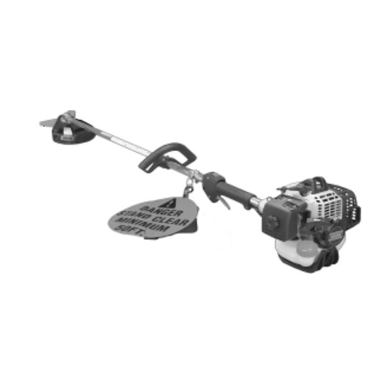
Grass Trimmer/Brush Cutter
Operator's Manual
MODELS
Read rules for safe operation and instructions carefully. ECHO provides an
Operator's Manual and a Safety Manual. Both must be read and understood for
proper and safe operation. Failure to do so could result in serous injury.
X7502095601
SRM - 260
SRM - 260S
Serial Number 03001001 - 03999999
WARNING
DANGER
X750001841
07/01
Advertisement
Table of Contents

Related Manuals for Echo SRM - 260S


Summary of Contents for Echo SRM - 260S
-
Page 1: Serial Number
Operator's Manual MODELS Read rules for safe operation and instructions carefully. ECHO provides an Operator's Manual and a Safety Manual. Both must be read and understood for proper and safe operation. Failure to do so could result in serous injury. - Page 3 If a decal cannot be read, a new one can be ordered from your ECHO dealer. See PARTS ORDERING instructions for specific information. Shaft Decal...
-
Page 4: International Symbols
• Beware of KICKOUT (blade thrust) when using blades. Special precautions are necessary for blade operation, see your Operator's and Safety Manuals. ONLY install ECHO approved blades on Brush Cutters (SRM) models equipped with proper blade shield, U-handles, harness, blade collar, nut and cotter pin. -
Page 5: Extended Operation
PERSONAL CONDITION AND SAFETY EQUIPMENT WARNING Trimmer/Brush Cutter users risk injury to themselves and others if the trimmer/brush cutter is used improperly and or safety precautions are not followed. Proper clothing and safety gear must be worn when operating a trimmer. -
Page 6: Repetitive Stress Injuries
Read and comply with all safety instructions listed in this manual and safety manual. ECHO, INC. will not be responsible for the failure of cutting devices, attachments or accessories which have not been tested and approved by ECHO. -
Page 7: Safe Operation
SAFE OPERATION WARNING Do not operate this product indoors or in inadequately ventilated areas. Engine exhaust contains poisonous emissions and can cause serious injury or death. • Provide all operators of this equipment with the Operator's Manual and instructions for safe operation. Keep A Firm Grip •... - Page 8 The ECHO product you purchased has been factory pre-assembled for your convenience. Due to packaging restrictions, shield installation and other assembly may be necessary. After opening the carton, check for damage. Immediately notify your retailer or ECHO Dealer of damaged or missing parts. Use the contents list to check for missing parts.
- Page 9 CUT-OFF KNIFE - Automatically trims line to the correct length: 5" after head is tapped on the ground. If trimmer is operated without a cut-off knife, the line will become too long, the engine will overheat, and engine damage may occur.
-
Page 10: Assembly Specifications
SSEMBLY SPECIFICATIONS i t i * Install and use U-Handle when operating any model with blade. i l - . l f ™... -
Page 11: Plastic Shield Installation
PLASTIC SHIELD INSTALLATION (for Nylon Line Operation) Tools Required: Screwdriver. Parts Required: Plastic Shield, Shield Plate, three (3) 5mm x 15mm screws. NOTE The plastic shield is for use with the Nylon Line Head only. Install Metal Shield when using plastic or metal blades. Remove plastic threaded shaft sleeve and adapter plate (C) from PTO shaft (A). -
Page 12: Operation With Blades
OPERATION WITH BLADES Preparing the Trimmer/Brush Cutter for Blade Use Blade use DEMANDS specific Brush Cutter configuration. Operation without specified shield and harness can result in serious personal injury. Plastic and Nylon Blades Require "Blade Conversion Kit," P/N 99944200415 (TRI-CUT [A] and shoulder harness [B]). -
Page 13: Harness Clamp Installation
76 mm (3 in.) diameter. Use Shoulder/Waist Harness (P/N 30100052131) Use of the Shoulder/ Waist Harness reduces operator fatigue and the possibility of blade contact with the operator's hands and feet by restricting trimmer movement. HARNESS CLAMP INSTALLATION (Plastic or Nylon Blade Use) Tools Required: Screwdriver, 8mm x 10mm Open-End Wrench. -
Page 14: Metal Shield Installation
Remove front handle. a. Remove four (4) screws and nuts and handle support from handle. b. Remove handle. Install clamp and front handle. Install gear housing with metal shield and blade. (See Metal Shield and Blade Installation Instructions below.) Balance unit. a. -
Page 15: U - Handle Installation
Install upper plate (D) on splined shaft. Blade installation requires use of Upper Plate (D) with 20mm pilot. Upper plate with 37mm pilot of the SRM-260/260S should be retained for use with nylon line head. Place Blade (E) over upper plate pilot, install the Lower Plate (F) and 10mm LH nut (G). - Page 16 14. Attach inner cable to swivel (C). Check throttle for freedom of movement and that wide open throttle / low idle extremes are adjusted properly. If adjustment cannot be achieved with adjusting nuts, consult with your Echo Dealer for correct adjustment procedure. 15. Connect ignition leads (A) and (B).
-
Page 17: Mixing Instructions
EPA Emission Defect Warranty Explanation.) IMPORTANT Echo Premium 2-Stroke Oil may be mixed at 50:1 ratio for application in all Echo engines sold in the past regardless of ratio specified in those manuals. Mixing Instructions Fill an approved fuel container with half of the required amount of gasoline. -
Page 18: Starting Cold Engine
WARNING The cutting attachment should not rotate at idle. If attachment rotates, readjust carburetor according to "Carburetor Adjustment" instructions in this manual or see your ECHO Dealer, otherwise serious personal injury may result. Stop Switch Move stop switch button (A) forward away from the STOP position. -
Page 19: Starting Warm Engine
WARNING If engine does not stop when stop switch is moved to STOP position, close choke - COLD START position - to stall engine. Have your ECHO dealer repair stop switch before using trimmer again. NOTE Refer to Grass Trimmer/Brush Cutter Safety Manual for proper and safe trimming techniques. -
Page 20: Skill Levels
ECHO Service Dealer for maintenance. To help you decide whether you want to DO-IT-YOURSELF or have the ECHO Dealer do it, each maintenance task has been graded. If a task is not listed, see your ECHO Dealer for repairs. -
Page 21: Air Filter
AIR FILTER Level 1. Tools required: Cleaning brush, 25 or 50 mm (1 or 2 in.) medium bristle paint brush. Parts required: 90030 REPOWER Close choke (Cold Start Position). This prevents dirt from entering the carburetor throat when the air filter is removed. Brush accumulated dirt from the air cleaner area. -
Page 22: Cooling Systems Cleaning
SPARK PLUG Level 2. Tools Required: T-Wrench (combination socket wrench and screw driver supplied with unit), Feeler gauge, preferably a wire gauge, Soft Metal Brush. Parts Required: REPOWER TUNE-UP KIT 90065 Remove spark plug and check for fouling, worn and rounded center electrode. -
Page 23: Exhaust System
Remove spark plug lead. Remove two (2) muffler cover screws and muffler cover (A). Remove screw and arm rest (B). Remove engine cover (C). IMPORTANT DO NOT use a metal scraper to remove dirt from the cylinder fins. Use brush to remove dirt from the cylinder fins. Remove grass and leaves from the grid between the recoil starter and fuel tank. -
Page 24: Carburetor Adjustment
The cylinder exhaust port must be inspected and cleaned of excess carbon every 3 months or 90 hours of operation in order to maintain this engine within the emissions durability period. ECHO strongly recommends that you return your unit to your ECHO dealer for this important maintenance service. CARBURETOR ADJUSTMENT... -
Page 25: Gear Housing
When carburetor adjustment is completed, the cutting attachment should not turn at idle, otherwise serious personal injury may result. LUBRICATION Level 1. Tools Required: 8 mm Open End Wrench, Screwdriver, Clean Rag. Parts Required: ECHO LUBE 8 oz. (P/N 91014) or Lithium Base ® Grease. Gear Housing Clean all loose debris from gear box. -
Page 26: Nylon Line Replacement
Level 1. Tools Required: Head locking tool (if head is to be removed) Parts Required: ECHO 0.095" Nylon Trimmer Line 12 m (40 feet) long. Hold drum (A) and turn spool (B) CW (clockwise) until it stops. Pull spool from drum. DO NOT push in on spool when turning. -
Page 27: Sharpening Metal Blades
SHARPENING METAL BLADES Three styles of metal blades are approved for use on the ECHO Brush Cutter. The 8-tooth blade can be sharpened during normal maintenance. The clearing blade and 80 tooth blade require professional service. Before sharpening, CLOSELY inspect blade for cracks (look at the bottom of each tooth and the center mounting hole closely), missing teeth and bending. -
Page 28: Troubleshooting
ROUBLESHOOTING t l i t l i Fuel vapors are extremely flammable and may cause fire and/or explosion. Never test for ignition spark near an open spark plug opening, otherwise serious personal injury may result. l f f t l i t l i t r i t r i... -
Page 29: Long Term Storage (Over 30 Days)
TORAGE Long Term Storage (over 30 days) During operation the muffler or catalytic muffler and surrounding cover become hot. Always keep exhaust area clear of flammable debris during transportation or when storing, otherwise serious property damage or personal injury may result. - Page 30 NOTES...
- Page 31 RASS RIMMER RUSH UTTER PERATOR ANUAL NOTES...
-
Page 32: Echo Consumer Product Support
• Purchasing from your Echo Dealer. • Sending a check or money order for $2.00 per Parts Catalog or $1.50 per Operator's Manual made payable to ECHO, INCORPORATED. State on a sheet of paper the model number and serial number of the ECHO unit you have, part number of the manual (if known), your name and address, and mail to address below. - Page 33 Some Echo units may be factory pre-assembled. The nylon line head, plastic debris shield, and mounting hardware shown in the contents list are pre-assembled to the unit. No assembly tools are needed. The front handle may need to be re-positioned for comfortable operation.