3Com OfficeConnect 3CRWE53172 User Manual
Wireless 11b cable/dsl gateway
Hide thumbs
Also See for OfficeConnect 3CRWE53172:
- Installation manual (2 pages) ,
- Datasheet (2 pages)

Related Manuals for 3Com OfficeConnect 3CRWE53172


Summary of Contents for 3Com OfficeConnect 3CRWE53172
- Page 1 OfficeConnect ® Wireless 11b Cable/DSL Gateway User Guide 3CRWE53172 http://www.3com.com/ Part No. DUA5317-2AAA02 Published July 2003...
- Page 2 3Com Corporation reserves the right to revise this documentation and to make changes in content from time 95052-8145 to time without obligation on the part of 3Com Corporation to provide notification of such revision or change. 3Com Corporation provides this documentation without warranty, term, or condition of any kind, either implied or expressed, including, but not limited to, the implied warranties, terms or conditions of merchantability, satisfactory quality, and fitness for a particular purpose.
-
Page 3: Table Of Contents
ONTENTS BOUT UIDE Naming Convention Conventions Feedback about this User Guide Related Documentation Product Registration NTRODUCING THE ATEWAY OfficeConnect Wireless 11b Cable/DSL Gateway Gateway Advantages Package Contents Minimum System and Component Requirements Front Panel Rear Panel ARDWARE NSTALLATION Introduction Safety Information Positioning the Gateway Using the Rubber Feet Wall Mounting... - Page 4 Macintosh Disabling PPPoE and PPTP Client Software Disabling Web Proxy UNNING THE ETUP IZARD Accessing the Wizard Password Time Zone WAN Settings LAN Settings DHCP Wireless Settings Summary ATEWAY ONFIGURATION Navigating Through the Gateway Configuration Pages Main Menu Option Tabs Welcome Screen Notice Board Password...
- Page 5 Special Applications PC Privileges URL Filter Security System Tools Restart Time Zone Configuration Upgrade Status and Logs Status Usage Logs Support/Feedback Support Feedback ROUBLESHOOTING Basic Connection Checks Browsing to the Gateway Configuration Screens Connecting to the Internet Forgotten Password and Reset to Factory Defaults Wireless Networking Alert LED Recovering from Corrupted Software...
- Page 6 DHCP Addressing Static Addressing Auto-IP Addressing ECHNICAL PECIFICATIONS Standards AFETY NFORMATION OFTWARE ICENSE GREEMENT ISP I NFORMATION LOSSARY NDEX 11B C /DSL EGULATORY OTICES FOR THE IRELESS ABLE ATEWAY...
-
Page 7: About This Guide
Cable/DSL Gateway and contains information that differs from the information in this guide, follow the information in the release note. Most user guides and release notes are available in Adobe Acrobat Reader Portable Document Format (PDF) on the 3Com World Wide Web site: http://www.3com.com... -
Page 8: Conventions
Feedback about this Your suggestions are very important to us. They will help make our User Guide documentation more useful to you. Please e-mail comments about this document to 3Com at: pddtechpubs_comments@3com.com Please include the following information when commenting: Document title... -
Page 9: Related Documentation
In addition to this guide, each Gateway document set includes one Documentation Installation Guide. This guide contains the instructions you need to install and configure your Gateway. Product Registration You can now register your Gateway on the 3Com web site and receive up-to-date information on your product: http://www.3com.com/register/... - Page 10 BOUT UIDE...
-
Page 11: Introducing The Gateway
NTRODUCING THE ATEWAY ® Welcome to the world of networking with 3Com . In the modern business environment, communication and sharing information is crucial. Computer networks have proved to be one of the fastest modes of communication but, until recently, only large businesses could afford the ®... - Page 12 1: I HAPTER NTRODUCING THE ATEWAY Figure 1 Example Network Without a Gateway When you use the Gateway in your network (Figure 2), it becomes your connection to the Internet. Connections can be made directly to the Gateway, or to an OfficeConnect Switch or Hub, expanding the number of computers you can have in your network.
-
Page 13: Gateway Advantages
Gateway Advantages Gateway The advantages of the Gateway include: Advantages Shared Internet connection for both wired and wireless computers 802.11b wireless networking No need for a dedicated, “always on” computer serving as your Internet connection Cross-platform operation for compatibility with Windows, Unix and Macintosh computers Easy-to-use, Web-based setup and configuration Provides centralization of all network address settings (DHCP) -
Page 14: Minimum System And Component Requirements
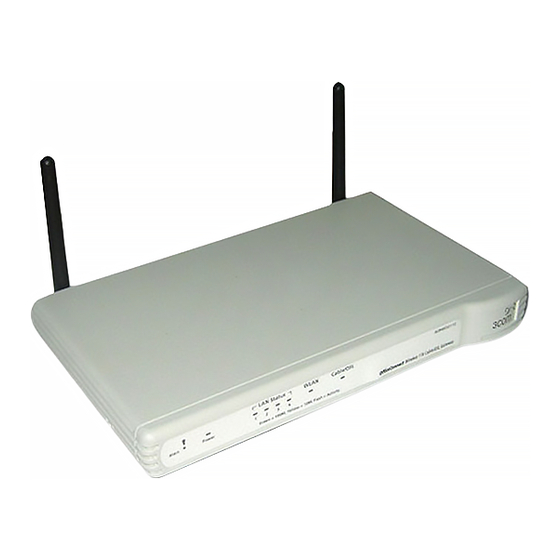
Front Panel The front panel of the Gateway contains a series of indicator lights (LEDs) that help describe the state of various networking and connection operations. Figure 3 Gateway - Front Panel 3CRWE53172 LAN Status WLAN Cable/DSL Alert OfficeConnect Wireless 11b Cable/DSL Gateway... - Page 15 Front Panel The administrator has invoked the Reset to Factory Defaults command, or The system software is in the process of being upgraded In each of these cases, wait until the Gateway has completed the current operation and the alert LED is Off. Flashing slowly - The Gateway has completed the Reset to Factory Defaults process, and is waiting for you to reset the unit.
-
Page 16: Rear Panel
1: I HAPTER NTRODUCING THE ATEWAY 5 Cable/DSL Status LED Green (100Mbps link) / yellow (10Mbps link) If the LED is on, the link between the Gateway and the cable or DSL modem is OK. If the LED is flashing, the link is OK and data is being transmitted or received. - Page 17 Rear Panel example, a hub or a switch). The LAN ports will automatically set themselves to MDI or MDIX depending on the device to which they are connected and the type of cable used.
- Page 18 1: I HAPTER NTRODUCING THE ATEWAY...
-
Page 19: Hardware Installation
ARDWARE NSTALLATION Introduction This chapter will guide you through a basic installation of the Gateway, including: Connecting the Gateway to the Internet. Connecting the Gateway to your network. Setting up your computers for networking with the Gateway. Safety Information WARNING: Please read the “Safety Information”... -
Page 20: Using The Rubber Feet
Water or moisture cannot enter the case of the unit. Air flow around the unit and through the vents in the side of the case is not restricted. 3Com recommends you provide a minimum of 25 mm (1 in.) clearance. -
Page 21: Before You Install Your Gateway
Before you Install your Gateway Before you Install Before you install and configure your Gateway, you need the following your Gateway additional information. If you do not have this information, contact your Internet Service Provider (ISP). Space is provided below for you to record this information. -
Page 22: Powering Up The Gateway
Internet. See Figure Figure 5 Connecting the Gateway Power Supply Unit Your existing Cable/DSL Modem 3Com OfficeConnect Wireless 11g Cable/DSL Gateway Wireless Users Your PC To use your Gateway to connect to the Internet through an external cable... - Page 23 Next you need to set up your computers so that they can make use of the Gateway to communicate with the Internet. 3Com recommends that you perform the initial Gateway configuration from a computer that is directly connected to one of the LAN ports.
- Page 24 2: H HAPTER ARDWARE NSTALLATION...
-
Page 25: Setting
ETTING OMPUTERS The Gateway has the ability to dynamically allocate network addresses to the computers on your network, using DHCP. However, your computers need to be configured correctly for this to take place. To change the configuration of your computers to allow this, follow the instructions in this chapter. - Page 26 3: S HAPTER ETTING OMPUTERS Figure 6 Local Area Properties Screen 6 Ensure that the options Obtain an IP Address automatically, and Obtain DNS server address automatically are both selected as shown in Figure Click OK. Figure 7 Internet Protocol (TCP/IP) Properties Screen 7 Restart your computer.
-
Page 27: Windows Xp
Obtaining an IP Address Automatically Windows XP 1 From the Windows Start menu, select Control Panel. 2 Click on Network and Internet Connections. 3 Click on the Network Connections icon. 4 Double click on LAN or High Speed Connection icon. A screen titled Local Area Connection Status will appear. -
Page 28: Disabling Pppoe And Pptp Client Software
3: S HAPTER ETTING OMPUTERS Disabling PPPoE If you have PPPoE or PPTP client software installed on your computer, you and PPTP Client will need to disable it. To do this: Software 1 From the Windows Start menu, select Settings > Control Panel. 2 Double click on Internet Options. -
Page 29: Running The Setup Wizard
UNNING THE ETUP IZARD Accessing the The Gateway setup program is Web-based, which means that it is Wizard accessed through your Web browser (Netscape Navigator 4.7 or higher, Internet Explorer 5.0 or higher, or Mozilla 1.2.1 or higher). To use the Setup Wizard: 1 Ensure that you have at least one computer connected to the Gateway. - Page 30 4: R HAPTER UNNING THE ETUP IZARD Figure 10 Gateway Login Screen 5 If the password is correct, the Country Selection screen will appear. Select the country you wish to configure the Gateway for, then click Apply. (Figure Figure 11 Country Selection Screen 6 When you have selected a country either: The Welcome screen will appear (Figure...
- Page 31 Accessing the Wizard If your Gateway has not been configured before, the Wizard will launch automatically (refer to Figure 13). 7 Click Next. 8 You will be guided step by step through a basic setup procedure. Figure 12 Welcome Screen Figure 13 Wizard Screen...
-
Page 32: Password
Old Password, then a new password in both the New Password and Confirm Password boxes. 3Com recommends entering a new password when setting up the Gateway for the first time. The Gateway is shipped from the factory with a default password, admin. -
Page 33: Wan Settings
Accessing the Wizard The Daylight Savings option advances the system clock by one hour. It does not cause the system clock to be updated for daylight savings time automatically. WAN Settings Figure 16 Internet Settings Screen This Internet Addressing Mode window allows you to set up the Gateway for the type of Internet connection you have. - Page 34 4: R HAPTER UNNING THE ETUP IZARD PPPoE Mode Figure 17 PPPoE Screen To setup the gateway for use with a PPP over Ethernet (PPPoE) connection, use the following procedure: 1 Enter your PPP over Ethernet user name in the PPPoE User Name text box. 2 Enter your PPP over Ethernet password in the PPPoE Password text box.
- Page 35 Accessing the Wizard Dynamic IP Address Mode To setup the Gateway for use with a dynamic IP address connection: 1 Select the ISP provides configuration dynamically (via DHCP) and then click Next. See Figure Figure 18 Hostname Screen 2 Some ISPs require a host name. If your ISP has this requirement, enter the host name in the Host Name text box (Figure 18) and click Next.
- Page 36 4: R HAPTER UNNING THE ETUP IZARD Static IP Mode To setup the Gateway for use with a static IP address connection, use the following procedure: 1 Select ISP has provided a static IP address, (see Figure 16) and then click Next.
- Page 37 Accessing the Wizard PPTP Mode Figure 21 PPTP Mode Screen To setup the gateway for use with a PPTP connection, use the following procedure: 1 Enter your PPTP server address in the PPTP Server Address text box. 2 Enter your PPTP user name in the PPTP User Name text box. 3 Enter your PPTP password in the PPTP Password text box.
-
Page 38: Lan Settings
4: R HAPTER UNNING THE ETUP IZARD 6 IP settings must be used when establishing a PPTP connection. Fill in the Initial IP Address and the Initial Subnet Mask fields if your ISP has provided you with these settings. Alternatively, if the PPTP server is located in your DSL modem, click Suggest to select an IP address on the same subnet as the PPTP server. -
Page 39: Wireless Settings
Selecting Clear Channel Select allows the Gateway to automatically select an available channel when first powered on. The Service Area Name default for 3Com products is “3Com”. Up to 32 (case sensitive) characters can be entered for the Service Area Name. -
Page 40: Summary
When you complete the Setup Wizard, a configuration summary will display. Verify the configuration information of the Gateway and then click Finish to save your settings. 3Com recommends that you print this page for your records. If you have made changes to the LAN Settings or wireless configuration options, you may need to reconfigure the computer you are using in order to make contact with the Gateway again. -
Page 41: Gateway Configuration
ATEWAY ONFIGURATION Navigating This chapter describes all the screens available through the Gateway Through the configuration pages, and is provided as a reference. To get to the Gateway configuration pages, browse to the Gateway by entering the URL in the location bar of your browser. -
Page 42: Option Tabs
Status and Logs — displays the current status and activity logs of the Gateway. Support/Feedback — contains a comprehensive online help system and allows you to provide 3Com with feedback on your Gateway. Option Tabs Each corresponding menu page may also provide sub-sections which are... -
Page 43: Password
Welcome Screen Password Figure 28 Password Screen Changing the Administration Password You can change the password to prevent unauthorized access to the Administration System. To do this: 1 Enter the current password in the Old Password field 2 Enter the new password in the New Password field 3 Enter the new password again in the Confirm Password field 4 Click Apply to save the new password The password is case sensitive. -
Page 44: Wizard
5: G HAPTER ATEWAY ONFIGURATION Wizard Figure 29 Wizard Screen Click WIZARD... to launch the configuration wizard. Refer to Chapter 4 for information on how to run the wizard. LAN Settings The LAN Settings menu provides the following options: Unit Configuration Figure 30 Unit Configuration Screen... -
Page 45: Dhcp Clients List
LAN Settings The LAN Settings screen is used to specify the LAN IP address of your Gateway, and to configure the DHCP server. 1 Select Unit Configuration and then specify the Gateway IP Address and Subnet Mask in the LAN Settings field. The default IP address of the Gateway is 192.168.1.1. - Page 46 5: G HAPTER ATEWAY ONFIGURATION client’s network card. Client Type — Whether the client is connected to the Gateway by wired or wireless connection. Fix — This box is checked if the IP address is fixed to the MAC address of the client’s network card.
-
Page 47: Wireless Settings
Wireless Settings Wireless Settings To improve the security of your wireless network, 3Com recommends that you: 1. Change the SSID from its default value - see page 48 2. Enable Encryption - see page 49 3. Enable Connection Control - see... - Page 48 The Service Area Name may also be referred to as “ESSID” depending on your networking vendor. By default the Gateway uses the name “3Com”. 3Com recommends that you change the default name. In order that your wireless computers can connect to the Gateway, you must: Use Infrastructure Mode not Adhoc Mode.
-
Page 49: Encryption
WPA provides a higher level of security, provided by its longer key and dynamic changes made to the key over time. 3Com recommends that you use WPA with any clients which support it. -
Page 50: Configuring Wep Encryption
5: G HAPTER ATEWAY ONFIGURATION Figure 33 Encryption Keys Screen showing WPA configuration To enter the pre-shared key as hexadecimal digits: 1 Select Enabled - Manual Pre-shared Key from the WPA Encryption Type drop-down box. 2 Enter a pair of hexadecimal digits in each of the 32 Key fields. Each field can contain a hexadecimal number from 00 to ff, for example 1a. - Page 51 Hexadecimal numbers are formed from 0-9 and A-F. 3Com Encryption String - This method is supported by 3Com Wireless products. The string can contain any alphanumeric characters and must be between 6 and 30 characters long. A single string will automatically generate 4 unique keys for 64 or 128 bit WEP.
- Page 52 4 Keys. You can leave a string blank provided this Key is not selected as the Active Transmit Key. Passphrase - This is another common method and similar to the 3Com Encryption string. In 64 bit WEP, the passphrase will generate 4 different keys.
-
Page 53: Connection Control
Wireless Settings Connection Control Figure 35 Connection Control Screen A higher level of security can be achieved for your wireless network if you use both encryption and you specify only certain wireless computers can connect to the Gateway. By default, any wireless computer that has the same Service Area Name/SSID, channel and encryption settings as the Gateway can connect to it. - Page 54 5: G HAPTER ATEWAY ONFIGURATION To create a list of Wireless computers that can access the Gateway: 1 Press New. The screen shown in Figure 36 opens. 2 Select the MAC addresses of the Wireless PCs for which you want to allow access.
-
Page 55: Client List
Wireless Settings Once an entry has been deleted it cannot be undone. Please wait 30 seconds for changes to take effect. Client List Figure 38 Client List Screen The Wireless Client List provides details on the devices that are connected to the Wireless LAN. - Page 56 2 Your browser will then prompt you to enter a file name and folder location in which to save the profile. Once the profile has been saved it can be copied on to another PC and imported into the 3Com Wireless Network Adapter.
-
Page 57: Internet Settings
Internet Settings Internet Settings Before you can configure the Gateway, you need to know the IP information allocation method used by your ISP. There are four different ways that ISPs can allocate IP information, as described below: 1 Static IP Address (DSL or Cable) The ISP provides the IP addressing information for you to enter manually. -
Page 58: Connection To Isp
5: G HAPTER ATEWAY ONFIGURATION When you install the Gateway, you will not need to use the dialup VPN on your PC anymore. Connection to ISP Figure 40 Connection to ISP Screen Before beginning this section, ensure you have the required information from your ISP. - Page 59 Internet Settings Static IP Address Figure 41 Connection Parameters Screen - Static IP To setup the Gateway for use with a Static IP address connection: 1 Select Static IP Address (to be specified manually) in the IP Allocation Mode field (Figure 41).
- Page 60 5: G HAPTER ATEWAY ONFIGURATION Dynamic IP Address Figure 42 Connection Parameters Screen - Dynamic IP If this mode is selected, your IP Address, Subnet Mask, and DNS Address will be obtained automatically from your ISP. They are not displayed on this screen, but may be viewed on the Status screen (click on Status and Logs on the left hand menu bar).
- Page 61 Internet Settings Use this PC’s MAC address - This field is automatically filled in with the MAC address of the PC you are using to configure the Gateway. You should use this address only if you were previously using this computer to connect directly to your modem.
- Page 62 5: G HAPTER ATEWAY ONFIGURATION 6 Enter your PPP over Ethernet service name in the PPPoE Service Name text box. Not all ISPs require a PPPoE service name. Only enter a service name if your ISP requires this. 7 Select an idle time from the Maximum Idle Time drop-down list. This value will correspond to the amount of idle time (no Internet activity) that will pass before the Gateway automatically ends your PPP over Ethernet session.
-
Page 63: Firewall
Firewall 5 Enter your Primary DNS Address and Secondary DNS address. Your ISP may provide you with primary and secondary DNS addresses. If they have been provided, enter the addresses in the appropriate text boxes. If not, leave 0.0.0.0 in the boxes. 6 Select an idle time from the Maximum Idle Time drop-down list. - Page 64 5: G HAPTER ATEWAY ONFIGURATION DMZ (De-Militarized Zone) Host is a computer without the protection of the firewall. This feature allows a single computer to be exposed to unrestricted 2-way communication from outside of your network. This feature should be used only if the Virtual Server or Special Applications options do not provide the level of access needed for certain applications.
-
Page 65: Special Applications
Firewall Or select Custom to specify a suitable name for the service and then enter the port numbers required for that service. (Figure Figure 47 Custom Setup Screen 4 Click Add to save the settings. The port numbers are specified using a comma-separated list, with hyphens to denote port number ranges. - Page 66 5: G HAPTER ATEWAY ONFIGURATION trigger port and incoming port(s), where traffic on the trigger port tells the firewall to open the incoming ports. Each defined Special Application only supports a single computer user, and up to 10 Special Applications can be defined. Any incoming ports opened by a Special Application trigger will be closed after five minutes of inactivity.
-
Page 67: Pc Privileges
Firewall Figure 50 Other Applications Setup Screen 3 Click Add to save your settings. Only one computer on your network can use the special application at any one time. PC Privileges Figure 51 PC Privileges Screen Select PC Privileges to display the PC Privilege setup screen (Figure 51). - Page 68 5: G HAPTER ATEWAY ONFIGURATION To use access control for all computers: 1 Click PCs access authorized services only. 2 Select All PCs to setup the access rights for all computers connected to the Gateway. 3 Select authorized services by clicking in the appropriate check box(es) (Figure 52).
-
Page 69: Url Filter
Firewall Figure 53 PC Privileges Setup Screen Example 5 Click Modify to save the settings or Close to discard them. To assign different access rights for different computers: 1 If not already selected, click PCs access authorized services only. 2 Click New to display the PC Privileges setting screen. 3 Enter the last digit(s) of the IP address of the computer in the PC’s IP Address text box. - Page 70 5: G HAPTER ATEWAY ONFIGURATION Deny List To allow users access to all Web sites except for those you choose to block, choose Deny List in the URL Filter Type drop-down box (Figure 54). Figure 54 URL Filter Screen showing Deny List To filter a specific site, enter the URL for that site.
- Page 71 Firewall contained within other words. For example, filtering the word sex would filter the following example URLs: www.sussex.com www.thisexample.com You can filter up to 30 keywords and URLs. Computers that should not be subject to URL filtering can be excluded by ticking the Bypass URL Filter checkbox in the PC Privileges setup screen.
- Page 72 5: G HAPTER ATEWAY ONFIGURATION Allow them individually by entering this.goodsite.com in one field and that.goodsite.com in another. Allow them by entering the keyword goodsite.com into one of the fields. This will allow all URLs containing the string goodsite.com. As well as allowing this.goodsite.com and that.goodsite.com, the keyword goodsite.com would allow sites that had the string goodsite.com in their URL, for example xxxgoodsite.com.
-
Page 73: Security
Gateway’s firewall settings. This reduces the configuration required but lessens your control of the Gateway’s firewall. 3Com recommends that you leave this feature disabled for maximum security. Allow PING from the Internet PING is a utility, which is used to determine whether a device is active at the specified IP address. - Page 74 This feature is enabled by clicking on the check box so that a tick can be seen and then select Apply. 3Com recommends that you leave this disabled. Enabling Remote Administration It is possible to administer the Gateway remotely. This can be set to one of four different levels using the following options: 1 Disable Remote Administration - This option is set as default.
-
Page 75: System Tools
System Tools System Tools The main frame of the System Tools screen includes four administration items: Restart, Time Zone, Configuration, and Upgrade (Figure 57). Restart Figure 57 Restart Screen If your Gateway is not operating correctly, you can choose to restart the Gateway by selecting Restart the Gateway, simulating the effect of power cycling the unit. -
Page 76: Time Zone
5: G HAPTER ATEWAY ONFIGURATION Time Zone Figure 58 Time Zone Screen Choose the time zone that is closest to your actual location. The time zone setting is used by the system clock when displaying the correct time in the log files. If you use Daylight saving tick the Enable Daylight savings box, and then click Apply (Figure... -
Page 77: Configuration
System Tools Configuration Figure 59 Configuration Screen Select the Configuration tab to display the Configuration screen (Figure 59). Backup Configuration Click BACKUP to save the current Gateway configuration. You will be prompted to download and save a file to disk. Restore Configuration Data If you want to reinstate the configuration settings previously saved to a file, press Browse to locate the backup file on your computer, and then... -
Page 78: Upgrade
Figure 60 Upgrade Screen The Upgrade facility allows you to install on the Gateway any new releases of system software that 3Com may make available. To install new software, you first need to download the software from the 3Com support web site to a folder on your computer. Once you have done this, select Browse to tell your web browser where this file is on your computer, and then click Apply. -
Page 79: Status
Status and Logs Status The Status screen displays a tabular representation of your network and Internet connection. (Figure Figure 61 Status Screen Usage Usage displays an approximate count of the traffic since the Gateway was last reset. (Figure The counts are approximate and should be used as a guide only. Contact your ISP for accurate logging information. -
Page 80: Logs
5: G HAPTER ATEWAY ONFIGURATION Figure 62 Usage Screen Logs Logs will allow you to view both the normal events, and security threats logged by the Gateway. Figure 63 Logs Screen You may be asked to refer to the information on the Status and Logs screens if you contact your supplier for technical support. -
Page 81: Support
Support/Feedback Support Figure 64 Support Screen Selecting the Support option on the main menu displays the support links screen, which contains a list of Internet links that provide information and support concerning the Gateway (Figure 64). Feedback Figure 65 Feedback Screen... - Page 82 5: G HAPTER ATEWAY ONFIGURATION Selecting the Feedback option displays the Feedback screen and allows you to provide feedback to 3Com on the operation of your Gateway (Figure 65). This screen should not be used to obtain technical support.
-
Page 83: Basic Connection Checks
ROUBLESHOOTING Basic Connection Check that the Gateway is connected to your computers and to the Checks cable/DSL modem, and that all the equipment is powered on. Check that the LAN Status and Cable/DSL Status LEDs on the Gateway are illuminated, and that any corresponding LEDs on the cable/DSL modem and the NIC are also illuminated. -
Page 84: Connecting To The Internet
6: T HAPTER ROUBLESHOOTING Connections tab and click on the LAN Settings button at the bottom. Make sure that the Proxy Server option is unchecked. If you cannot browse to the Gateway, use the winipcfg utility in Windows 95/98/ME to verify that your computer has received the correct address information from the Gateway. -
Page 85: Forgotten Password And Reset To Factory Defaults
Forgotten Password and Reset to Factory Defaults Forgotten Password If you can browse to the Gateway configuration screen but cannot log on and Reset to because you do not know or have forgotten the password, follow the Factory Defaults steps below to reset the Gateway to it’s factory default configuration. CAUTION: All your configuration changes will be lost, and you will need to run the configuration wizard again before you can re-establish your Gateway connection to the Internet. - Page 86 6: T HAPTER ROUBLESHOOTING If you have a wired and a wireless NIC in the same computer, ensure that the wired NIC is disabled. Check the status of the Gateway Wireless LED, it should be lit if wireless is enabled and will flash when there is wireless activity. If not lit go to “Wireless Settings”...
-
Page 87: Alert Led
If the Alert LED comes on continuously again, then a fault has been detected. Locate the copy of the Gateway software on the accompanying CD-ROM or 3Com web site ( ) and upload it to the Gateway to see if http://www.3com.com... -
Page 88: Recovering From Corrupted Software
Ensure that one of your computers has a copy of the new software image file stored on its hard disk or available on CD-ROM. The latest software is available on 3Com’s Web site at: www.3com.com. 1 Remove power from the Gateway and disconnect the Cable/DSL modem and all your computers, except for the one computer with the software image. -
Page 89: Frequently Asked Questions
Internet can connect to, but this is not a recommended configuration. Where can I download software updates for the Gateway? Updates to the Gateway software are posted on the 3Com support web site, accessible by visiting: http://www.3com.com... - Page 90 HAPTER ROUBLESHOOTING The 3Com Knowledgebase at: http://knowledgebase.3com.com is a database of technical information covering all 3Com products. It is updated daily with information from 3Com technical support services, and it is available 24 hours a day, 7 days a week.
-
Page 91: Using
SING ISCOVERY Running the 3Com provides a user friendly Discovery application for detecting the Discovery Gateway on the network. Application Windows Installation (95/98/2000/Me/NT) 1 Insert the Gateway CD-ROM in the CD-ROM drive on your computer. A menu will appear; select Gateway Discovery. - Page 92 A: U PPENDIX SING ISCOVERY Figure 67 Discovered Gateway Screen Figure 68 shows an example Discovered Devices screen. Highlight the Wireless Cable/DSL Gateway by clicking on it, and press Next. Figure 68 Discovery Finish Screen 4 Click on Finish to launch a web browser and display the login page for the Gateway.
-
Page 93: Ip Addressing
IP A DDRESSING The Internet The Internet protocol suite consists of a well-defined set of Protocol Suite communications protocols and several standard application protocols. Transmission Control Protocol/Internet Protocol (TCP/IP) is probably the most widely known and is a combination of two of the protocols (IP and TCP) working together. - Page 94 B: IP A PPENDIX DDRESSING For your network to work correctly, all devices on the network must have: The same sub-network address. The same subnet mask. The only value that will be different is the specific host device number. This value must always be unique. An example IP address is ‘192.168.100.8’.
-
Page 95: How Does A Device Obtain An Ip Address And Subnet Mask
How does a Device Obtain an IP Address and Subnet Mask? This type of IP Address operates on a subnet mask of ‘255.255.0.0’. Table 4 for an example about how a network (only four computers represented) and a Gateway might be configured. Table 4 IP Addressing and Subnet Masking Device IP Address... - Page 96 B: IP A PPENDIX DDRESSING an IP address at random from the industry standard subnet of 169.254.x.x (with a subnet mask of 255.255.0.0). If two devices allocate themselves the same address, the conflict is detected and one of the devices allocates itself a new address. Automatic IP addressing support was introduced by Microsoft in the Windows 98 operating system and is also supported in Windows 2000.
-
Page 97: T Echnical S Pecifications
ECHNICAL PECIFICATIONS This section lists the technical specifications for the OfficeConnect Wireless 11b Cable/DSL Gateway. Wireless 11b Interfaces Cable/DSL Gateway Cable/DSL modem connection — 10Mbps/100Mbps dual speed Ethernet port (10BASE-T/100BASE-TX) LAN connection — four 10Mbps/100Mbps dual speed Ethernet ports (10BASE-T/100BASE-TX) WLAN Interfaces Standard IEEE 802.11b, Direct Sequence Spread Spectrum (DSSS) Transmission rate: 11bps, automatic fallback to 5.5, 2, or 1 Mbps... - Page 98 C: T PPENDIX ECHNICAL PECIFICATIONS Dimensions Width = 220 mm (8.7 in.) Depth = 135 mm (5.3 in.) Height = 24 mm (1 in.) Weight Approximately 500 g (1.1 lbs) Standards Functional: ISO 8802/3 IEEE 802.3 IEEE 802.11b, Wi-Fi Safety: UL60950 CSA 22.2 #60950 IEC 60950...
- Page 99 Windows 2000 Windows XP Mac OS 8.5 or higher Unix Ethernet Performance The Gateway complies to the IEEE 802.3i, u and x specifications. Wireless Performance The Gateway has been designed to conform to the Wi-Fi interoperability test standard. Cable Specifications The Gateway supports the following cable types and maximum lengths: Category 3 (Ethernet) or Category 5 (Fast Ethernet or Dual Speed Ethernet) Twisted Pair —...
- Page 100 C: T PPENDIX ECHNICAL PECIFICATIONS...
- Page 101 AFETY NFORMATION Important Safety Information WARNING: Warnings contain directions that you must follow for your personal safety. Follow all directions carefully. You must read the following safety information carefully before you install or remove the unit: WARNING: The Gateway generates and uses radio frequency (rf) energy. In some environments, the use of rf energy is not permitted.
- Page 102 D: S PPENDIX AFETY NFORMATION WARNING: Disconnect the power adapter before moving the unit. WARNING: RJ-45 ports. These are shielded RJ-45 data sockets. They cannot be used as telephone sockets. Only connect RJ-45 data connectors to these sockets. Wichtige Sicherheitshinweise VORSICHT: Warnhinweise enthalten Anweisungen, die Sie zu Ihrer eigenen Sicherheit befolgen müssen.
- Page 103 VORSICHT: Es sind keine von dem Benutzer zu ersetzende oder zu wartende Teile in dem Gerät vorhanden. Wenn Sie ein Problem mit dem Gateway haben, das nicht mittels der Fehleranalyse in dieser Anleitung behoben werden kann, setzen Sie sich mit Ihrem Lieferanten in Verbindung.
- Page 104 D: S PPENDIX AFETY NFORMATION AVERTISSEMENT: L’appareil fonctionne à une tension extrêmement basse de sécurité qui est conforme à la norme CEI 60950. Ces conditions ne sont maintenues que si l'équipement auquel il est raccordé fonctionne dans les mêmes conditions. AVERTISSEMENT: Il n’y a pas de parties remplaceables par les utilisateurs ou entretenues par les utilisateurs à...
-
Page 105: End User Software License Agreement
Subject to the restrictions set forth herein, the Software is licensed to be used on any workstation or any network server owned by or leased to you, for your internal use, provided that the Software is used only in connection with this 3Com product. You may reproduce and provide one (1) copy of the Software and Documentation for each such workstation or network server on which the Software is used as permitted hereunder. - Page 106 Software and Documentation, and may be amended only in a writing signed by both parties. Should you have any questions concerning this Agreement or if you desire to contact 3Com for any reason, please contact the 3Com subsidiary serving your country, or write: 3Com Corporation, 5500 Great America Parkway, P.O.
- Page 107 ISP I NFORMATION Information Regarding Popular ISPs WAN Types Characteristics Popular ISPs Dynamic IP Cable modem ISP, non-hostname MediaOne, RoadRunner, based. Need to clone the MAC Optimum Online, Time Warner, (Clone MAC) address in the Advanced tab of Charter, Adelphia, Metrocast. the Internet Settings page.
- Page 108 F: ISP I PPENDIX NFORMATION Static DSL Modem, always on. Need to CableSpeed, Cnet, Direct Link, enter ALL IP information from ISP Drizzle, DSL Extreme, Earthlink (DSL) in the Static IP address section of Wireless, Fast Point, Flashcom, the Internet Settings page. GTE-WhirlWind, Heavenet, HSA Corp, I-55, InterAccess, LinkLine, Mission, Nauticom, NAS, Omitel,...
- Page 109 LOSSARY 802.11b The IEEE specification for wireless Ethernet which allows speeds of up to 11 Mbps. The standard provides for 1, 2, 5.5 and 11 Mbps data rates. The rates will switch automatically depending on range and environment. 802.11g The IEEE specification for wireless Ethernet which allows speeds of up to 54 Mbps.
- Page 110 LOSSARY Auto-negotiation Some devices in the OfficeConnect range support auto-negotiation. Auto-negotiation is where two devices sharing a link, automatically configure to use the best common speed. The order of preference (best first) is: 100BASE-TX full duplex, 100BASE-TX half duplex, 10BASE-T full duplex, and 10BASE-T half duplex.
- Page 111 DNS Server Address DNS stands for Domain Name System, which allows Internet host computers to have a domain name (such as 3com.com) and one or more IP addresses (such as 192.34.45.8). A DNS server keeps a database of host computers and their respective domain names and IP addresses, so that when a domain name is requested (as in typing “3com.com”...
- Page 112 LOSSARY Half Duplex A system that allows packets to transmitted and received, but not at the same time. Contrast with full duplex. A device that regenerates LAN traffic so that the transmission distance of that signal can be extended. Hubs are similar to repeaters, in that they connect LANs of the same type;...
- Page 113 LOSSARY small geographic area (usually not larger than a floor or building). LANs are characterized by high transmission speeds over short distances (up to 1000 metres). Media Access Control. A protocol specified by the IEEE for determining which devices have access to a network at any one time. MAC Address Media Access Control Address.
- Page 114 LOSSARY Server A computer in a network that is shared by multiple end stations. Servers provide end stations with access to shared network services such as computer files and printer queues. SSID Service Set Identifier. Some vendors of wireless products use SSID interchangeably with ESSID.
- Page 115 LOSSARY URL Filter A URL Filter is a feature of a firewall that allows it to stop its clients form browsing inappropriate Web sites. Wide Area Network. A network that connects computers located in geographically separate areas (for example, different buildings, cities, or countries).
- Page 116 LOSSARY...
- Page 117 NDEX Internet addresses 93 Access Rights 69 Internet Addressing Mode 33 Addresses Internet Settings 57 IP 93 dynamic IP address 57 Administration Password 32, 43 PPPoE 57 Automatic Addressing 95 PPTP 57 static IP address 57 IP Address 21, 36, 38, 45, 93 IP Allocation 58 Cable Specifications 99 ISP Connection 58...
- Page 118 NDEX NIC 14 service area name 48 Remote Administration 74 settings 39, 47 Reset to Factory Defaults 77, 85 Restart 75 Safety Information 19 Security 73 Setup Wizard 29, 44 Special Applications 65 Specifications technical 97 Static Addressing 95 Static IP Address 57, 59 Status 79 Subnet Mask 36, 38, 93 Summary 40...
- Page 119 EGULATORY OTICES FOR THE 11B C /DSL IRELESS ABLE ATEWAY Channels Use of the Wireless Cable/DSL Gateway is only authorized for the channels approved by each country. For proper installation, login to the management interface and select your country from the drop down list. Table 5 below details the channels permitted by the local regulatory agencies:...
- Page 120 frequency energy and, if not installed and used in accordance with the instructions, may cause harmful interference to radio communications. However, there is no guarantee that interference will not occur in a particular installation. Information to the If this equipment does cause interference to radio or television reception, User which can be determined by turning the equipment off and on, the user is encouraged to try to correct the interference by one or more of the...
- Page 121 15.109 (g)Class B Radiated Emissions Limits Exposure to Radio Frequency Radiation: The radiated output power of the 3Com OfficeConnect Wireless Cable/DSL Gateway is far below the FCC radio frequency exposure limits. Nevertheless, the 3Com OfficeConnect Wireless Cable/DSL Gateway shall be used in such manner that the potential for human contact during normal operation is minimized.
- Page 122 FCC Section 2.1091. Statement (U.S.) In order to comply with the FCC RF exposure requirements, the 3Com OfficeConnect Wireless Cable/DSL Gateway must only be installed with approved antennas and a minimum separation distance of 20 cm (8 in) must be maintained from the antenna to any nearby persons.
- Page 124 3Com Corporation, Corporate Headquarters, Copyright © 2003 3Com Corporation. All rights reserved. 5500 Great America Parkway, Santa Clara, 3Com and OfficeConnect are registered trademarks of CA 95052-8145, USA. 3Com Corporation. All other company and product names may be trademarks of their respective companies.