Biostar MCP6P-M2 Setup Manual
Setup manual
Hide thumbs
Also See for MCP6P-M2:
- Manual (39 pages) ,
- Quick installation manual (2 pages) ,
- Setup manual (45 pages)
Table of Contents
Advertisement
MCP6P-M2 Setup Manual
FCC Information and Copyright
This equipment has been tes ted and found to comply with the limits of a Class
B digital devic e, purs uant to Part 15 of the FCC Rules . T hese limits are designed
to provide reasonable protec tion against harmful interference in a residential
installation. T his equipment generates , uses , and c an radiate radio frequency
energy and, if not ins talled and used in accordance with the instructions , may
cause harmful interference to radio communications . There is no guarantee
that interference will not occur in a particular ins tallation.
The vendor makes no representations or warranties with respec t to the
contents here and s pecially disclaims any implied warranties of merchantability
or fitness for any purpose. Further the vendor reserves the right to revise this
publication and to make c hanges to the c ontents here without obligation to
notify any party beforehand.
D uplication of this publication, in part or in whole, is not allowed without first
obtaining the vendor's approval in writing.
The content of this user's manual is subject to be c hanged without notice and
we will not be res ponsible for any mis takes found in this user's manual. All the
brand and produc t names are trademarks of their respec tive companies .
Advertisement
Table of Contents

Related Manuals for Biostar MCP6P-M2


Summary of Contents for Biostar MCP6P-M2
- Page 1 MCP6P-M2 Setup Manual FCC Information and Copyright This equipment has been tes ted and found to comply with the limits of a Class B digital devic e, purs uant to Part 15 of the FCC Rules . T hese limits are designed to provide reasonable protec tion against harmful interference in a residential installation.
-
Page 2: Table Of Contents
Table of Contents Chapter 1: Introduction.............3 Before You Start..............3 Package Checklist..............3 Motherboard Features............4 Rear Panel Connectors............5 Motherboard Layout ............6 Chapter 2: Hardware Installation........7 Installing Central Processing Unit (CPU) ........ 7 FAN Headers................ 9 Installing System Memory.............10 Connectors and Slots ............12 Chapter 3: Headers &... -
Page 3: Chapter 1: Introduction
MCP6P-M2 CHAPTER 1: INTRODUCTION EFORE T ART Thank you for choosing our product. Be fore you start installing the mothe rboard, please make sure you follow the instructions be low: Prepare a dry and stable work ing environment with sufficie nt lighting. -
Page 4: Motherboard Features
Motherboard Manual OT HERBOARD EAT URES SPEC Socket AM2 AMD 64 Architectu re enables 32 and 64 bit compu ting AMD Ath lon 64 / Ath lon 64 FX / Athlon 64 Supports Hyper Tran sport and Cool=n =Quiet x2 / Sempron processors Supports up to 1 GHz Bandwidth Support HyperTran sport Chipset... -
Page 5: Rear Panel Connectors
Board Size 190 mm(W) x 244 mm(L) Special RAID 0 / 1 / 0+1 / 5 support Features Biostar Reserves the righ t to add or remove support for OS Support Windows 2000 / XP / VISTA any OS With or without notice. ANEL... -
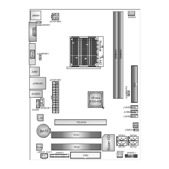
Page 6: Motherboard Layout
Motherboard Manual OT HERBOARD AYOUT JKBMS1 JCFA N1 JATXP WR4 JKBM SPWR1 J US BPWR1 JUSB1 JATXP WR1 JUSBLAN1 JA UDIO1 nForce 6100-430 J US B3 JA UDIOF 1 JCDIN1 JUSB2 J US B4 L AN PCI-EX16 BIOS J CMOS1 BAT1 PCI1 SATA 3... -
Page 7: Chapter 2: Hardware Installation
MCP6P-M2 CHAPTER 2: HARDWARE INSTALLATION (CPU) NST ALLING ENT RAL ROCESSING Step 1: Remove the socket protection cap. Step 2: Pull the lever toward direction A from the socket and then raise the lever up to a 90-degree angle. Step 3: Look for the white triangle on socket, and the gold triangle on CPU should point towards this white triangle. - Page 8 Motherboard Manual Step 4: Hold the CPU down firmly, and then close the lever toward direct B to complete the installation. Step 5: Put the CPU Fan on the CPU and buckle it. Connect the CPU FAN power cable to the JCFAN1. This completes the installation.
-
Page 9: Fan Headers
MCP6P-M2 FAN H EADERS These fan headers support cooling-fans built in the computer. The fan cable and connector may be different according to the fan manufacturer. Connect the fan cable to the connector while matching the black wire to pin#1. -
Page 10: Installing System Memory
Motherboard Manual NST ALLING YST EM EMORY A. Memory Modules Unlock a DIMM slot by pressing the retaining clips outward. Align a DIMM on the slot such that the notch on the DIMM matches the break on the Slot. Insert the DIMM vertically and firmly into the slot until the retaining chip snap back in place and the DIMM is properly seated. - Page 11 MCP6P-M2 B. Memory Capacity DIMM Socket Total Memory DDR2 Module Location Size DIMMA1 256MB/512MB/1GB/2GB Max is 4GB. DIMMB1 256MB/512MB/1GB/2GB C. Dual Channel Memory installation To trigger the Dual Channel f unction of the motherboard, the memory module must meet the following requirements: Install memory module of the same density in pair, shown in the f ollowing table.
-
Page 12: Connectors And Slots
Motherboard Manual ONNECT ORS AND LOT S FDD1: Floppy Disk Conne ctor The motherboard prov ides a standard floppy disk connector that supports 360K, 720K, 1.2M, 1.44M and 2.88M floppy disk ty pes. This connector supports the prov ided f loppy drive ribbon cables. IDE1: Hard Disk Conne ctor The motherboard has a 32-bit Enhanced PCI IDE Controller that prov ides PIO Mode 0~4, Bus Master, and Ultra DMA 33/66/100/133 f unctionality. - Page 13 MCP6P-M2 PCI-EX16: PCI-Express x16 Slot PCI-Express 1.0a compliant. Maximum theoretical realized bandwidth of 4GB/s simultaneously per direction, f or an aggregate of 8GB/s totally. PCI-Express supports a raw bit-rate of 2.5GB/s on the data pins. 2X bandwidth ov er the traditional PCI architecture.
-
Page 14: Chapter 3: Headers & Jumpers Setup
Motherboard Manual CHAPTER 3: HEADERS & JUMPERS SETUP OW T O ET UP UMPERS The illustration shows how to set up jumpers. When the jumper cap is placed on pins, the jumper is “close”, if not, that means the jumper is “open”. - Page 15 MCP6P-M2 JATXPWR1: ATX Powe r Source Conne ctor This connector allows user to connect 24-pin power connector on the ATX power supply. Assignment Assignment +3.3V +3.3V -12V +3.3V Ground Ground PS_ON Ground Ground Ground Ground Ground PW_OK Standby Voltage+5V +12V...
- Page 16 Motherboard Manual JUSB2/JUSB3/JUSB4: He ade rs for USB 2.0 Ports at Front Panel This header allows user to connect additional USB cable on the PC f ront panel, and also can be connected with internal USB devices, like USB card reader. Assignment +5V (fused) JUSB3...
-
Page 17: Front Panel Audio Header
MCP6P-M2 JAUDIO F1: Front Panel Audio Heade r This header allows user to connect the front audio output cable with the PC f ront panel. This header allows only HD audio front panel connector; AC’97 connector is not acceptable. Assignment... - Page 18 Motherboard Manual JSPDIF_O UT1: Digital Audio-out Conne ctor This connector allows user to connect the PCI bracket SPDIF output header. Assignment SPDIF_OUT Ground JCMO S1: Cle ar CMOS Heade r By placing the jumper on pin2-3, it allows user to restore the BIOS saf e setting and the CMOS data, please carefully f ollow the procedures to avoid damaging the motherboard.
- Page 19 MCP6P-M2 JPRNT1: Printe r Port Connector This header allows you to connector printer on the PC. Assignment Assignment -Strobe Ground -ALF Data 6 Data 0 Ground -Error Data 7 Data 1 Ground -Init -ACK Data 2 Ground -Scltin Busy Data 3...
-
Page 20: Power Source Headers For Usb Ports
Motherboard Manual JUSBPWR1/JUSBPWR2: Powe r Source Heade rs for USB Ports Pin 1-2 Close: JUSBPWR1: +5V for USB ports at JUSB1/JUSBLAN1. JUSBPWR2: +5V for USB ports at f ront panel (JUSB2/JUSB3/JUSB4). Pin 2-3 Close: JUSBPWR1: USB ports at JUSB1/JUSBLAN1 are powered by +5V standby v oltage. -
Page 21: Chapter 4: Raid Functions
MCP6P-M2 CHAPTER 4: RAID FUNCTIONS PERAT ION YST EM Supports Windows XP Home/Prof essional Edition, and Windows 2000 Prof essional. RRAYS RAID supports the following types of RAID arrays: RAID 0: RAID 0 defines a disk striping scheme that improves disk read and write times for many applications. - Page 22 Motherboard Manual RAID 1: Every read and write is actually carried out in parallel across 2 disk drives in a RAID 1 array system. The mirrored (backup) copy of the data can reside on the same disk or on a second redundant drive in the array.
- Page 23 MCP6P-M2 RAID 0+1: RAID 0 drives can be mirrored using RAID 1 techniques. Resulting in a RAID 0+1 solution for improved performance plus resiliency. Features and Benefits Drives: Minimum 4, and maximum is 6 or 8, depending on the platform.
- Page 24 Motherboard Manual RAID 5: RAID 5 stripes both data and parity information across three or more drives. It writes data and parity blocks across all the drives in the array. Fault tolerance is maintained by ensuring that the parity information for any given block of data is placed on a different drive from those used to store the data itself.
-
Page 25: Chapter 5: Useful Help
MCP6P-M2 CHAPTER 5: USEFUL HELP RIVER NST ALLAT ION OT E After you installed your operating system, please insert the Fully Setup Driver CD into your optical drive and install the driver for better system performance. You will see the following window after you insert the CD The setup guide will auto detect your motherboard and operating system. -
Page 26: Award Bios Beep Code
Motherboard Manual BIOS B WARD Beep Sound Meaning One long beep followed by two short Video card not found or v ideo card beeps memory bad High-low siren sound CPU overheated System will shut down automatically One Short beep when system boot-up No error found during POST Long beeps every other second No DRAM detected or install XT RA... -
Page 27: Troubleshooting
MCP6P-M2 ROUBLESHOOT ING Probable Solution No power to the system at all Make sure power cable is Power light don’t illuminate, f an securely plugged in. inside power supply does not turn Replace cable. Contact technical support. Indicator light on key board does not turn on. -
Page 28: Appendencies: Spec In Other Language
Motherboard Manual APPENDENCIES: SPEC IN OTHER LANGUAGE ERMAN Spezifikationen Sockel AM2 Die AMD 64-Architektur un terstü tzt eine 32-Bit- und AMD Ath lon 64 / Ath lon 64 FX / Athlon 64 64-Bit-Daten verarbeitung x2 / Sempron Prozessoren Unterstü tzt Hyper Tran sport und Cool’n’Qu iet Unterstü... - Page 29 190 mm (B) X 244 mm (L) Sonderfun kti Unterstü tzt RAID 0 / 1 / 0+1 / 5 onen Biostar behält sich das Recht vor , ohn e An kündigung OS-Un terstüt Windows 2000 / XP / VISTA die Un terstützung für ein Betriebssystem zung hinzu zufügen oder zu entfernen .
-
Page 30: France
Motherboard Manual RANCE SPEC Socket AM2 L'architecture AMD 64 permet le calcul 32 et 64 bits Processeu rs AMD Ath lon 64 / Athlon 64 FX Prend en charge Hyper Tran sport et Cool’n ’Quiet / Ath lon 64 x2 / Sempron Prend en charge Hyper Tran sport ju squ'à... - Page 31 Prise en charge RAID 0 / 1 / 0 +1 / 5 spéciales Biostar se réserve le droit d'ajouter ou de supprimer le Support SE Windows 2000 / XP / VISTA support de SE avec ou san s préavis.
-
Page 32: Italian
Motherboard Manual T ALIAN SPECIFICA Socket AM2 L’architettura AMD 64 abilita l a computazione 32 Processori AMD Athlon 64 / Athlo n 64 e 64 bit FX / Athlon 64 x 2 / Sempro n Supporto di Hyper Tra nsport e Cool’ n’Quiet Supporto di Hyper Transport fi no a1 GHz di larghezza di banda Chipset... - Page 33 Caratterist iche Supporto RAID 0 / 1 / 0+1 / 5 speciali Sistemi Biostar si riserva il diritto di aggiungere o operativi Windows 2000 / XP / VISTA rimuovere il supporto di qualsiasi sistema supportati operativo se nza pre avviso.
-
Page 34: Spanish
Motherboard Manual PANISH Especificación Conector AM2 La arqu itectu ra AMD 64 permite el procesado de 32 y Procesadores AMD Athlon 64 / Ath lon 64 64 bits FX / Ath lon 64 x2 / Sempron Soporta las tecnologías Hyper T ran sport y Cool’n’Qu iet Admite HyperTran sport con un an cho de banda de hasta1 GHz Conjunto de... - Page 35 Admite RAID 0 / 1 / 0 +1 / 5 especiales Soporte de Biostar se reserva el derecho de añ adir o retirar el sistema Windows 2000 / XP / VISTA soporte de cualquier SO con o sin aviso previo.
-
Page 36: Portuguese
Motherboard Manual ORT UGUESE ESPECIFICAÇÕES Socket AM2 A arquitectu ra AMD 64 permite uma compu tação de 32 Processadores AMD Ath lon 64 / Ath lon 64 e 64 bits FX / Ath lon 64 x2 / Sempron Suporta as tecn ologias Hyper Tran sport e Cool’n ’Qu iet Suporta a tecnologia HyperT ransport com uma largura de banda até1 GHz Chipset... - Page 37 Característi Suporta as funções RAID 0 / 1 / 0 +1 / 5 especiais Sistemas A Biostar reserva-se o direito de adicionar ou remover operativos Windows 2000 / XP / VISTA suporte para qualquer sistema operativo com ou sem suportados...
-
Page 38: Polish
Motherboard Manual OLISH SPEC Socket AM2 Architektu ra AMD 64 umożliwia przetwarzanie 32 i 64 Procesor AMD Ath lon 64 / Ath lon 64 FX / Athlon 64 bitowe x2 / Sempron Procesory Obsługa Hyper T ransport oraz Cool’n ’Qu iet Obsługa HyperT ran sport o szerokości pasma do1 GHz Chipset... - Page 39 190 mm (S) X 244 mm (W) płyty Funkcj e Obsługa RAID 0 / 1 / 0 +1 / 5 specjaln e Obsluga Biostar zastrzega sobie prawo dodawania lub systemu Windows 2000 / XP / VISTA odwoływania obsługi dowoln ego systemu operacyjne operacyjnego bez powiadomien ia.
-
Page 40: Russian
Motherboard Manual USSIAN СПЕЦ Гнездо AM2 Архитектура AMD 64 разрешат ь обработка данных (центральн Процессоры AMD Ath lon 64 / Athlon 64 на 32 и 64 бит ый FX / Ath lon 64 X2 / Sempron Поддержка Hyper Tran sport и Cool’n’Qu iet процессор) Поддержка... - Page 41 ые технически Поддержка RAID 0 / 1 / 0+1 / 5 е характери с тики Biostar сохран яет за собой право добавлять или Поддержка Windows 2000 / XP / VISTA удалять средства обеспечения для OS с или без предварительного уведомления.
-
Page 42: Arabic
Motherboard Manual RABIC اﻟﻤﻮاﺻﻔﺎت ﻡﻘﺒﺲAM2 ﺗﻤﻜﻦ ﺗﻘﻨﻴﺔAMD 64 ﺏﺖ و إﺝﺮاء اﻟﻌ ﻤ ﻠﻴﺎت ا ﻟﺤﺎﺳﻮﺏﻴﺔ ﺏﺴ ﺮﻋﺔ وﺣﺪة ا ﻟﻤﻌ ﺎ ﻟﺠﺔ ﻡﻌ ﺎ ﻟﺠﺎتAMD Athlon 64 / Athlon 64 FX / ﺗﺪﻋﻢ ﺗﻘﻨﻴﺔHyper T ransport وCool’n ’Quiet اﻟﻤﺮآ... - Page 43 ﺗﺪﻋﻢ ﺗﻘﻨﻴﺔRAID 0 / 1 / 0+1 / 5 ﻡﺰاﻳﺎ ﺥﺎﺹﺔ ارﺗﻔﺎع ﻡﻢ ﻋﺮض ﻡﻢ ﺣﺠﻢ اﻟﻠﻮﺣﺔ Windows 2000 / XP / VISTA ﺗﺤﺘﻔﻆBiostar ﺏﺤﻘﻬﺎ ﻓﻲ إﺿﺎﻓﺔ أو إز ا ﻟﺔ اﻟﺪﻋﻢ ﻷ ي ﻥﻈﺎم ﺗﺸﻐﻴﻞ ﺏﺈﺥﻄﺎ ر أو ﺏﺪون إﺥﻄﺎ ر دﻋﻢ أﻥﻈﻤﺔ ا ﻟﺘﺸﻐﻴﻞ...
-
Page 44: Japanese
Motherboard Manual APANESE 仕様 AMD 64 アーキテクチャでは、32 ビットと64 ビット計算が可 Socket AM2 能です AMD Ath lon 64 / Ath lon 64 FX / Athlon 64 ハイパートランスポートとクールアンドクワイアットをサポ x2/ Sempron プロセッサ ートします 1GHzのバンド幅までハイパートランスポート をサポートします チップセット nForce 6100-430 DDR2 DIMMスロット x 2 デュアル チャンネルモードDDR2 メモリモジュール 最大メモリ容量4GB DDR2 533 / 667 / 800をサポート... - Page 45 MCP6P-M2 仕様 SATAコネクタ 各コネクタは1 つのSATAデバイスをサポートします フロントパネルコネクタ フロントパネル機能をサポートします フロントオーディオコネクタ フロントパネルオーディオ機能をサポートします CDインコネクタ CDオーディオイン機能をサポートします S/PDIFアウトコネクタ デジタルオーディオアウト機能をサポートします CPUファンヘッダ CPUファン電源装置(スマートファン機能を搭載) システムファンヘッダ システムファン電源装置 CMOSクリアヘッダ 各コネクタは2 つのフロントパネルUSBポートをサポートし USBコネクタ ます 電源コネクタ(24 ピン) 電源コネクタ(4 ピン) PS/2 キーボード PS/2 マウス VGAポート 背面パネル シリアルポート LANポート USBポート オーディオジャック ボードサイズ 190 mm (幅) X 244 mm (高さ) RAID 0 / 1 / 0+1 / 5 のサポート...