Table of Contents
Advertisement
Available languages
Available languages
MCP6PB M2+/N68S Setup Manual
FCC Information and Copyright
This equipment has been tested and found to comply with the limits of a Class
B digital device, pursuant to Part 15 of the FCC Rules. These limits are designed
to provide reasonable protection against harmful interference in a residential
installation. This equipment generates, uses, and can radiate radio frequency
energy and, if not installed and used in accordance with the instructions, may
cause harmful interference to radio communications. There is no guarantee
that interference will not occur in a particular installation.
The vendor makes no representations or warranties with respect to the
contents here and specially disclaims any implied warranties of merchantability
or fitness for any purpose. Further the vendor reserves the right to revise this
publication and to make changes to the contents here without obligation to
notify any party beforehand.
Duplication of this publication, in part or in whole, is not allowed without first
obtaining the vendor's approval in writing.
The content of this user's manual is subject to be changed without notice and
we will not be responsible for any mistakes found in this user's manual. All the
brand and product names are trademarks of their respective companies.
Advertisement
Table of Contents

Related Manuals for Biostar MCP6PB M2 PLUS


Summary of Contents for Biostar MCP6PB M2 PLUS
- Page 1 MCP6PB M2+/N68S Setup Manual FCC Information and Copyright This equipment has been tested and found to comply with the limits of a Class B digital device, pursuant to Part 15 of the FCC Rules. These limits are designed to provide reasonable protection against harmful interference in a residential installation.
-
Page 2: Table Of Contents
Table of Contents Chapter 1: Introduction ........1 Before You Start ................1 Package Checklist ................1 Motherboard Features..............2 Rear Panel Connectors ..............3 Motherboard Layout................. 4 Chapter 2: Hardware Installation ......5 Installing Central Processing Unit (CPU)........5 FAN Headers.................. -
Page 3: Chapter 1: Introduction
MCP6PB M2+/N68S CHAPTER 1: INTRODUCTION EFORE TART Thank you for choosing our product. Before you start installing the motherboard, please make sure you follow the instructions below: Prepare a dry and stable working environment with sufficient lighting. Always disconnect the computer from power outlet before operation. -
Page 4: Motherboard Features
Motherboard Manual OTHERBOARD EATURES SPEC Socket AM2+ AMD 64 Architecture enables 32 and 64 bit AMD Phenom / Phenom II / Athlon / Athlon computing II / Sempron processors Supports Hyper Transport and PowerNow (Maximum Watt: 95W) Support HyperTransport 1.0 Ghz Supports up to 2 GT/s Bandwidth GeForce 6150 SE/nForce 430 (MCP6P M2+) Chipset... -
Page 5: Rear Panel Connectors
Board Size 170 mm(W) x 235 mm(L) MicroATX Special RAID 0 / 1 Features Biostar Reserves the right to add or remove support OS Support Windows XP / Vista / 7 for any OS With or without notice. ANEL ONNECTORS... -
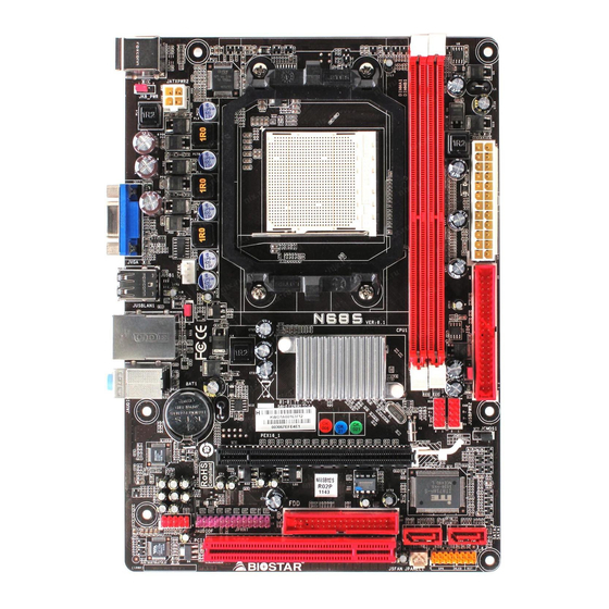
Page 6: Motherboard Layout
Motherboard Manual OTHERBOARD AYOUT JKB MS JKB_PWR JATXPWR2 JATXPWR1 JUSB1 JCFAN JUSBPWR1 JUSBLA N1 GeForce 6150SE/7025 nForce 430/630a JA UDIO1 JUSBPWR2 BAT1 JCOM JUSB2 JCMOS1 PEX16_1 BIOS Super I/O JPRNT JAUDIOF PCI1 SATA2 SATA1 Codec JPANEL1 JSFAN Note: represents the 1 pin. -
Page 7: Chapter 2: Hardware Installation
MCP6PB M2+/N68S CHAPTER 2: HARDWARE INSTALLATION (CPU) NSTALLING ENTRAL ROCESSING Step 1: Remove the socket protection cap. Step 2: Pull the lever toward direction A from the socket and then raise the lever up to a 90-degree angle. Step 3: Look for the white triangle on socket, and the gold triangle on CPU should point towards this white triangle. - Page 8 Motherboard Manual Step 4: Hold the CPU down firmly, and then close the lever toward direct B to complete the installation. Step 5: Put the CPU Fan on the CPU and buckle it. Connect the CPU FAN power cable to the JCFAN. This completes the installation. Note: Please update the BIOS to the latest version while using AM2+ CPUs.
-
Page 9: Fan Headers
MCP6PB M2+/N68S FAN H EADERS These fan headers support cooling-fans built in the computer. The fan cable and connector may be different according to the fan manufacturer. Connect the fan cable to the connector while matching the black wire to pin#1. -
Page 10: Installing System Memory
Motherboard Manual NSTALLING YSTEM EMORY A. Memory Modules Unlock a DIMM slot by pressing the retaining clips outward. Align a DIMM on the slot so that the notch on the DIMM matches the break on the Slot. Insert the DIMM vertically and firmly into the slot until the retaining chip snap back in place and the DIMM is properly seated. - Page 11 MCP6PB M2+/N68S B. Memory Capacity DIMM Socket Total Memory DDR2 Module Location Size DIMMA1 256MB/512MB/1GB/2GB Max is 4GB. DIMMB1 256MB/512MB/1GB/2GB C. Dual Channel Memory installation To trigger the Dual Channel function of the motherboard, the memory module must meet the following requirements: Install memory module of the same density in pairs, shown in the following table.
-
Page 12: Connectors And Slots
Motherboard Manual ONNECTORS AND LOTS FDD: Floppy Disk Connector The motherboard provides a standard floppy disk connector that supports 360K, 720K, 1.2M, 1.44M and 2.88M floppy disk types. This connector supports the provided floppy drive ribbon cable. IDE: IDE/ATAPI Connector The motherboard has a 32-bit Enhanced PCI IDE Controller that provides PIO Mode 0~4, Bus Master, and Ultra DMA 33/66/100/133 functionality. - Page 13 MCP6PB M2+/N68S PEX16_1: PCI-Express Gen2 x16 Slot PCI-Express 1.0a compliant. Maximum theoretical realized bandwidth of 4GB/s simultaneously per direction, for an aggregate of 8GB/s totally. PCI-Express supports a raw bit-rate of 2.5Gb/s on the data pins. 2X bandwidth over the traditional PCI architecture. PEX16_1 PCI1: Peripheral Component Interconnect Slot This motherboard is equipped with 1 standard PCI slot.
-
Page 14: Chapter 3: Headers & Jumpers Setup
Motherboard Manual CHAPTER 3: HEADERS & JUMPERS SETUP OW TO ETUP UMPERS The illustration shows how to set up jumpers. When the jumper cap is placed on pins, the jumper is “close”, if not, that means the jumper is “open”. Pin opened Pin closed Pin1-2 closed... - Page 15 MCP6PB M2+/N68S JATXPWR1: ATX Power Source Connector This connector allows user to connect 24-pin power connector on the ATX power supply. Assignment Assignment +3.3V +3.3V -12V +3.3V Ground Ground PS_ON Ground Ground Ground Ground Ground PW_OK Standby Voltage+5V +12V +12V Ground +3.3V JATXPWR2: ATX Power Source Connector...
- Page 16 Motherboard Manual JUSB2/JUSB3: Headers for USB 2.0 Ports at Front Panel These headers allow user to connect additional USB cable on the PC front panel, and also can be connected with internal USB devices, like USB card reader. Assignment +5V (fused) +5V (fused) USB- JU SB2 JU SB3...
- Page 17 MCP6PB M2+/N68S JAUDIOF: Front Panel Audio Header This header allows user to connect the front audio output cable with the PC front panel. This header allows only HD audio front panel connector; AC’97 connector is not acceptable. Assignment Mic Left in Ground Mic Right in GPIO...
-
Page 18: Clear Cmos Procedures
Motherboard Manual JCMOS1: Clear CMOS Header By placing the jumper on pin2-3, it allows user to restore the BIOS safe setting and the CMOS data, please carefully follow the procedures to avoid damaging the motherboard. Pin 1-2 Close: Normal Operation (default). Pin 2-3 Close: Clear CMOS data. - Page 19 MCP6PB M2+/N68S JPRNT: Printer Port Connector This header allows you to connect printer port on the PC. Assignment Assignment -Strobe Ground -ALF Data 6 Data 0 Ground -Error Data 7 Data 1 Ground -Init -ACK Data 2 Ground -Scltin Busy Data 3 Ground Ground...
- Page 20 Motherboard Manual JUSBPWR1/JUSBPWR2: Power Source Headers for USB Ports Pin 1-2 Close: JUSBPWR1: +5V for USB ports at JUSB1/JUSBLAN1. JUSBPWR2: +5V for USB ports at front panel (JUSB2/JUSB3). Pin 2-3 Close: JUSBPWR1: +5V STB for USB ports at JUSB1/JUSBLAN1. JUSBPWR2: +5V STB for USB ports at front panel (JUSB2/JUSB3). JUSBPWR1 Pin 1-2 close JUSBPWR2...
-
Page 21: Chapter 4: Raid Functions
MCP6PB M2+/N68S CHAPTER 4: RAID FUNCTIONS PERATING YSTEM Supports Windows XP and Windows Vista. RRAYS RAID supports the following types of RAID arrays: RAID 0: RAID 0 defines a disk striping scheme that improves disk read and write times for many applications. - Page 22 Motherboard Manual RAID 1: Every read and write is actually carried out in parallel across 2 disk drives in a RAID 1 array system. The mirrored (backup) copy of the data can reside on the same disk or on a second redundant drive in the array.
-
Page 23: Chapter 5: Useful Help
MCP6PB M2+/N68S CHAPTER 5: USEFUL HELP RIVER NSTALLATION After you installed your operating system, please insert the Fully Setup Driver CD into your optical drive and install the driver for better system performance. You will see the following window after you insert the CD The setup guide will auto detect your motherboard and operating system. -
Page 24: Software
Motherboard Manual OFTWARE Installing Software 1. Insert the Setup CD to the optical drive. The drivers installation program would appear if the Autorun function has been enabled. 2. Select Software Installation, and then click on the respective software title. 3. Follow the on-screen instructions to complete the installation. BIOScreen Utility This utility allows you to personalize your boot logo easily. -
Page 25: Award Bios Beep Code
MCP6PB M2+/N68S BIOS B WARD Beep Sound Meaning One long beep followed by two short Video card not found or video card beeps memory bad High-low siren sound CPU overheated System will shut down automatically One Short beep when system boot-up No error found during POST Long beeps every other second No DRAM detected or install... -
Page 26: Troubleshooting
Motherboard Manual ROUBLESHOOTING Probable Solution There is no power in the system. Make sure power cable is Power LED does not shine; the securely plugged in. fan of the power supply does not Replace cable. work Contact technical support. Indicator light on keyboard does not shine. - Page 27 MCP6PB M2+/N68S This page is intentionally left blank.
-
Page 28: Appendix: Spec In Other Languages
Motherboard Manual APPENDIX: SPEC IN OTHER LANGUAGES ERMAN Spezifikationen Sockel AM2+ Die AMD 64-Architektur unterstützt eine 32-Bit- und AMD Phenom / Phenom II / Athlon / Athlon 64-Bit-Datenverarbeitung II / Sempron Prozessoren Unterstützt Hyper Transport und PowerNow (Maximales Watt: 95W) Unterstützt HyperTransport 2.0 Ghz mit einer Bandbreite von bis zu 4 GT/s... - Page 29 Platinengröß 170 mm (B) X 235 mm (L) Sonderfunkti Unterstützt RAID 0 / 1 onen Biostar behält sich das Recht vor , ohne Ankündigung OS-Unterstü Windows XP / Vista / 7 die Unterstützung für ein Betriebssystem tzung hinzuzufügen oder zu entfernen.
-
Page 30: French
Motherboard Manual RENCH SPEC Socket AM2+ Processeurs AMD Phenom / Phenom II / L'architecture AMD 64 permet le calcul 32 et 64 bits Athlon / Athlon II / Sempron Prend en charge Hyper Transport et PowerNow (Watt maximum : 95W) Prend en charge Hyper Transport 2.0 Ghz Bus frontal jusqu'à... - Page 31 170 mm (l) X 235 mm (H) carte Fonctionnal ités Prise en charge RAID 0 / 1 spéciales Biostar se réserve le droit d'ajouter ou de supprimer le Support SE Windows XP / Vista / 7 support de SE avec ou sans préavis.
-
Page 32: Italian
Motherboard Manual TALIAN SPECIFICA Socket AM2+ L’architettura AMD 64 abilita la co mputazione 32 Processori AMD Phenom / Phenom II / e 64 bit Athlon / Athlon II / Sempron Supporto di Hyper Transport e PowerNow (Watt massimo: 95W) Supporto di HyperTransport 2.0 Ghz fino a 4 GT/s di larghezza di banda GeForce 6150 SE/nForce 430 (MCP6P M2+) Chipset... - Page 33 170 mm (larghezza) x 235 mm i scheda (altezza) Caratterist Supporto RAID 0 / 1 iche speciali Sistemi Biostar si riserva il diritto di aggiungere o operativi Windows XP / Vista / 7 rimuovere il supporto di qualsiasi sistema supportati operativo senza preavviso.
-
Page 34: Spanish
Motherboard Manual PANISH Especificación Conector AM2+ La arquitectura AMD 64 permite el procesado de 32 y Procesadores AMD Phenom / Phenom II / 64 bits Athlon / Athlon II / Sempron Soporta las tecnologías Hyper Transport y PowerNow (Vatio máximo: 95W) Admite HyperTransport 2.0 Ghz con un ancho de banda de hasta 4 GT/s Conjunto... - Page 35 170 mm. (A) X 235 Mm. (H) la placa Funciones Admite RAID 0 / 1 especiales Soporte de Biostar se reserva el derecho de añadir o retirar el Windows XP / Vista / 7 sistema soporte de cualquier SO con o sin aviso previo. operativo...
-
Page 36: Portuguese
Motherboard Manual ORTUGUESE ESPECIFICAÇÕES Socket AM2+ A arquitectura AMD 64 permite uma computação de Processadores AMD Phenom / Phenom II 32 e 64 bits / Athlon / Athlon II / Sempron Suporta as tecnologias Hyper Transport e PowerNow (Watt máximo: 95W) Suporta a tecnologia HyperTransport 2.0 Ghz com uma largura de banda até... - Page 37 170 mm (L) X 235 mm (A) da placa Característi Suporta as funções RAID 0 / 1 especiais Sistemas A Biostar reserva-se o direito de adicionar ou remover operativos Windows XP / Vista / 7 suporte para qualquer sistema operativo com ou sem suportados aviso prévio.
-
Page 38: Polish
Motherboard Manual OLISH SPEC Socket AM2+ Architektura AMD 64 umożliwia przetwarzanie 32 i 64 AMD Phenom / Phenom II / Athlon / Procesor bitowe Athlon II / Sempron Procesory Obsługa Hyper Transport oraz PowerNow (Maksymalny Watt: 95W) Obsługa HyperTransport 2.0 Ghz o szerokości pasma do 4 GT/s GeForce 6150 SE/nForce 430 (MCP6P M2+) Chipset... - Page 39 Gniazdo audio Wymiary 170 mm (S) X 235 mm (W) płyty Funkcje Obsługa RAID 0 / 1 specjalne Obsluga Biostar zastrzega sobie prawo dodawania lub systemu Windows XP / Vista / 7 odwoływania obsługi dowolnego systemu operacyjne operacyjnego bez powiadomienia.
-
Page 40: Russian
Motherboard Manual USSIAN СПЕЦ Гнездо AM2+ (централь Архитектура AMD 64 разрешать обработка данных Процессоры AMD Phenom / Phenom II / на 32 и 64 бит ный Athlon / Athlon II / Sempron процессор Поддержка Hyper Transport и PowerNow (Максимальный ватт: 95W) Поддержка... - Page 41 170 мм (Ш) X 235 мм (В) панели Специальн ые техническ Поддержка RAID 0 / 1 ие характери стики Biostar сохраняет за собой право добавлять или Поддержк Windows XP / Vista / 7 удалять средства обеспечения для OS с или без а OS предварительного уведомления.
-
Page 42: Arabic
Motherboard Manual RABIC اﻟﻤﻮاﺻﻔﺎت ﻡﻘﺒﺲAM2+ ﺗﻤﻜﻦ ﺗﻘﻨﻴﺔAMD 64 ﻡﻌﺎﻟﺠﺎتAMD Phenom / Phenom II / Athlon / ﺑﺖ و إﺟﺮاء اﻟﻌﻤﻠﻴﺎت اﻟﺤﺎﺳﻮﺑﻴﺔ ﺑﺴﺮﻋﺔ اﻟﻤﻌﺎﻟﺠﺔ وﺡﺪة ﺗﺪﻋﻢ ﺗﻘﻨﻴﺔHyper Transport و 3 PowerNow Athlon II / Sempron اﻟﻤﺮآﺰیﺔ ()و59 :ﻗﺼ ﻮى واط 4 GT/s ﺗﺪﻋﻢ... - Page 43 ﻡﻨﺎﻓﺬ ﻋﺪ ﻡﻘﺒﺲ ﺹﻮت ارﺗﻔﺎع ﻡﻢ ﻋﺮض ﻡﻢ اﻟﻠﻮﺡﺔ ﺡﺠﻢ ﺗﺪﻋﻢ ﺗﻘﻨﻴﺔRAID 0 / 1 ﻡﺰایﺎ ﺥﺎﺹﺔ ﺗﺤﺘﻔﻆBiostar ﺑﺤﻘﻬﺎ ﻓﻲ إﺿﺎﻓﺔ أو إزاﻟﺔ اﻟﺪﻋﻢ ﻷي ﻥﻈﺎم ﺗﺸﻐﻴﻞ ﺑﺈﺥﻄﺎر أو Windows XP / Vista / 7 اﻟﺘﺸﻐﻴﻞ أﻥﻈﻤﺔ دﻋﻢ ﺑﺪون إﺥﻄﺎر...
-
Page 44: Japanese
Motherboard Manual APANESE 仕様 Socket AM2+ AMD 64アーキテクチャでは、 32ビットと64ビット計算が可 AMD Phenom / Phenom II / Athlon / 能です Athlon II / Sempron プロセッサ ハイパートランスポートとクールアンドクワイアットをサポ (最高のワット: 95W) ートします 4 GT/sのバンド幅までハイパートランスポー ト2.0 GHzをサポートします GeForce 6150 SE/nForce 430 (MCP6P M2+) チップセッ GeForce 7025/nForce 630a (N68S) ト... - Page 45 各コネクタは2つのフロントパネルUSBポートをサポートし USBコネクタ ます 電源コネクタ(24ピン) 電源コネクタ(4ピン) プリンタポートコネクタ 各コネクタは1つのプリンタポートをサポートします シリアルポートコネクタ PS/2キーボード PS/2マウス VGAポート 背面パネル LANポート USBポート オーディオジャック ボードサイ 170 mm (幅) X 235 mm (高さ) ズ RAID 0 / 1 のサポート 特殊機能 Biostarは事前のサポートなしにOSサポートを追加または削 OSサポート Windows XP / Vista / 7 除する権利を留保します。 2010/05/04...