Table of Contents
Advertisement
Advertisement
Table of Contents

Related Manuals for Cisco AIR-BR350-A-K9 - Aironet 350 Wireless Bridge


Summary of Contents for Cisco AIR-BR350-A-K9 - Aironet 350 Wireless Bridge
- Page 1 Cisco Aironet 350 Series Bridge Hardware Installation Guide Corporate Headquarters Cisco Systems, Inc. 170 West Tasman Drive San Jose, CA 95134-1706 http://www.cisco.com Tel: 408 526-4000 800 553-NETS (6387) Fax: 408 526-4100 Text Part Number: OL-0658-01...
- Page 2 You can determine whether your equipment is causing interference by turning it off. If the interference stops, it was probably caused by the Cisco equipment or one of its peripheral devices. If the equipment causes interference to radio or television reception, try to correct the interference by using one or more of the following measures: •...
-
Page 3: Table Of Contents
Repeater Unit That Extends Wireless Range Bridge Operating as a Root Access Point Bridge Specifications Installation C H A P T E R Cautions and Warnings Installation Guidelines Basic Guidelines Antenna Options Cisco Aironet 350 Series Bridge Hardware Installation Guide OL-1412-01... - Page 4 Installation and Grounding Warning Declarations of Conformity and Regulatory Information A P P E N D I X Manufacturers Federal Communication Commission Declaration of Conformity Statement Department of Communications – Canada Canadian Compliance Statement Cisco Aironet 350 Series Bridge Hardware Installation Guide OL-1412-01...
- Page 5 European Community, Switzerland, Norway, Iceland, and Liechtenstein Declaration of Conformity with Regard to the R&TTE Directive 1999/5/EC Declaration of Conformity for RF Exposure Guidelines for Operating Cisco Aironet Access Points and Bridges in Japan Declaration of Conformity Statements Declaration of Conformity Statement for European Union Countries...
- Page 6 Contents Cisco Aironet 350 Series Bridge Hardware Installation Guide OL-1412-01...
-
Page 7: Preface
This section describes the objectives, audience, organization, and conventions of the Cisco Aironet 350 Series Bridge Hardware Installation Guide. Objectives This publication explains the steps for initial setup and configuration of the Cisco Aironet 350 Series Bridge (here after referred to as the bridge). This publication also provides troubleshooting information and detailed specifications. -
Page 8: Organization
Means reader take note. Notes contain helpful suggestions or references to materials not contained in Note this manual. Means reader be careful. In this situation, you might do something that could result in equipment Caution damage or loss of data. Cisco Aironet 350 Series Bridge Hardware Installation Guide viii OL-1412-01... -
Page 9: Related Publications
For more information about bridges and related products, refer to the following publications: • Quick Start Guide: Cisco Aironet 350 Series Bridge describes how to connect and power up the bridge, assign an IP address, and configure the bridge for basic operation. -
Page 10: Ordering Documentation
The Cisco TAC website is located at this URL: http://www.cisco.com/tac Accessing all the tools on the Cisco TAC website requires a Cisco.com user ID and password. If you have a valid service contract but do not have a login ID or password, register at this URL: http://tools.cisco.com/RPF/register/register.do... -
Page 11: Opening A Tac Case
TAC Case Open Tool automatically recommends resources for an immediate solution. If your issue is not resolved using the recommended resources, your case will be assigned to a Cisco TAC engineer. The online TAC Case Open Tool is located at this URL: http://www.cisco.com/tac/caseopen For P1 or P2 cases (P1 and P2 cases are those in which your production network is down or severely degraded) or if you do not have Internet access, contact Cisco TAC by telephone. - Page 12 Preface Obtaining Additional Publications and Information Cisco Press publishes a wide range of general networking, training and certification titles. Both new • and experienced users will benefit from these publications. For current Cisco Press titles and other information, go to Cisco Press online at this URL: http://www.ciscopress.com...
-
Page 13: Chapter 1 Overview
C H A P T E R Overview Cisco Aironet 350 Series Bridges are wireless LAN transceivers that connect two or more remote networks into a single LAN. The bridge can also be used as a rugged access point, providing network access to wireless client devices. -
Page 14: Key Features
• A power patch panel, such as the Cisco Catalyst Inline Power Patch Panel • Cisco Aironet 340 series bridges rely on a separate power supply plugged into the power port on the back Note of the bridge. Cisco Aironet power injectors are designed for use with 350 series access points and bridges only. Using Caution the power injector with other Ethernet-ready devices can damage the equipment. -
Page 15: Indicator Lights
• The radio indicator blinks green to indicate radio traffic activity. The light is normally off, but it blinks green whenever a packet is received or transmitted over the bridge’s radio. Cisco Aironet 350 Series Bridge Hardware Installation Guide OL-1412-01... -
Page 16: Network Configuration Examples
1-2, packets sent between the file server and Workstation B or Workstation C go through the non-root bridges over the wireless link. Data packets sent from Workstation A to the file server go through the wired LAN segment and do not go across the wireless link. Cisco Aironet 350 Series Bridge Hardware Installation Guide OL-1412-01... -
Page 17: Repeater Unit That Extends Wireless Range
LAN. When you configure a bridge as a repeater access point, the Spanning-Tree Protocol is deactivated. If you use a bridge as a repeater, the data throughput is cut in half. Cisco Aironet 350 Series Bridge Hardware Installation Guide OL-1412-01... -
Page 18: Bridge Operating As A Root Access Point
Bridge Operating as a Root Access Point File server LAN segment A LEFT SERI AL PORT RIGH T/PR IMAR Y ONLI NE POW ER ETHE RNET Bridge (root unit) Workstation A Workstation Laptop Workstation Cisco Aironet 350 Series Bridge Hardware Installation Guide OL-1412-01... -
Page 19: Bridge Specifications
Class B, EN 50082-1, UL1950, CSA 22.2 No. 950, EN 60950, IEC 60950, VCCI, and others (see Appendix B). 350 series bridge complies with UL 2043 for products installed in air handling spaces, such as above suspended ceilings. Cisco Aironet 350 Series Bridge Hardware Installation Guide OL-1412-01... - Page 20 Chapter 1 Overview Bridge Specifications Cisco Aironet 350 Series Bridge Hardware Installation Guide OL-1412-01...
-
Page 21: Chapter 2 Installation
This chapter describes the setup of the bridge and includes the following sections: Cautions and Warnings • Installation Guidelines • Unpacking the Bridge • Connecting the Antenna Cable • Connecting the Ethernet Cables • Cisco Aironet 350 Series Bridge Hardware Installation Guide OL-1412-01... -
Page 22: Cautions And Warnings
Cisco Aironet power injectors are designed for use with 350 series access points and bridges only. Using Caution the power injector with other Ethernet-ready devices can damage the equipment. The operational voltage range for Cisco Aironet 350 series access points and bridges is 24 to 60 VDC. Caution Higher voltage can damage the equipment. -
Page 23: Installation Guidelines
Obstructions – A physical obstruction such as a building or a tree can block or hinder • communication between bridges. Avoid locating the antennas in a location where there is an obstruction between the sending and receiving antennas. Cisco Aironet 350 Series Bridge Hardware Installation Guide OL-1412-01... - Page 24 Building materials – Radio penetration is greatly influenced by the building material used in • construction. For example, drywall construction allows greater range than concrete blocks. Metal or steel construction is a barrier to radio signals. Cisco Aironet 350 Series Bridge Hardware Installation Guide OL-1412-01...
-
Page 25: Unpacking The Bridge
• Warning labels • Plastic tie wraps, wall anchor, and screw • Cisco product registration card • Note If any item is damaged or missing, notify your authorized Cisco sales representative. Cisco Aironet 350 Series Bridge Hardware Installation Guide OL-1412-01... -
Page 26: Connecting The Antenna Cable
350 series bridge power options include: • A switch with inline power, such as a Cisco Catalyst 3524-PWR-XL An inline power patch panel, such as a Cisco Catalyst Inline Power Patch Panel • A Cisco Aironet power injector •... - Page 27 Cisco Aironet power injectors are designed for use with 350 series access points and bridges only. Using the power injector with other Ethernet-ready devices can damage the equipment. The operational voltage range for Cisco Aironet 350 series access points and bridges is 24 to 60 VDC. Caution Higher voltage can damage the equipment.
- Page 28 During normal operation, the LEDs blink green. Refer to Chapter 4, “Troubleshooting,” for LED descriptions. Follow the steps in Chapter 3, “Basic Configuration,” to assign basic settings to the bridge. Step 4 Cisco Aironet 350 Series Bridge Hardware Installation Guide OL-1412-01...
-
Page 29: Chapter 3 Basic Configuration
Telnet session, or a Simple Network Management Protocol (SNMP) application. Consult Chapter 2 in the Cisco Aironet 350 Series Bridge Software Configuration Guide for SNMP instructions and for complete descriptions of these interfaces. -
Page 30: Before You Start
IP address and the SSID. Obtaining and Installing IPSU IPSU is available on the Cisco web site. Follow these steps to obtain and install IPSU: Cisco Aironet 350 Series Bridge Hardware Installation Guide... -
Page 31: Finding The Bridge's Ip Address
Chapter 3 Basic Configuration Using the IP Setup Utility Use your Internet browser to access the Cisco Software Center at the following URL: Step 1 http://www.cisco.com/public/sw-center/sw-wireless.shtml Locate the bridge utilities section and click on the Windows link. Step 2 Click on the file, IPSUvxxxxx.exe. The vxxxxxx identifies the software package version number. -
Page 32: Setting The Bridge's Ip Address And Ssid
This section provides instructions for performing a basic configuration of your bridge using your Internet browser, the bridge’s serial port, or a Telnet session. Consult Chapter 2 in the Cisco Aironet 350 Series Bridge Software Configuration Guide for instructions Note on using SNMP to configure the bridge. -
Page 33: Using An Internet Browser
Express Setup page (see Figure 3-1). Note The bridge is compatible with Microsoft Internet Explorer versions 4.0 or later and Netscape Communicator versions 4.0 or later. Figure 3-1 The Express Setup Page Cisco Aironet 350 Series Bridge Hardware Installation Guide OL-1412-01... - Page 34 The Configuration Server link takes you to the Boot Server Setup page, which you use to configure the bridge to work with your network’s BOOTP or DHCP servers for automatic assignment of IP addresses. Cisco recommends assigning a static IP address to your bridge to simplify network management and to Note prevent delays in receiving an address through DHCP.
- Page 35 Step 12 an Ensure Compatibility With option: • 2Mb/sec clients—Select this setting if your network contains Cisco Aironet devices that operate at 2 Mbps. • non-Aironet 802.11—Select this setting if the bridge is operating as an access point and there are non-Cisco Aironet devices on your wireless LAN.
-
Page 36: Using The Command-Line Interface
Click the SNMP link to go to the SNMP Setup page, where you can edit other SNMP settings. You can define other SNMP communities with User Management. The “Security Setup” section in Chapter 3 of the Cisco Aironet 350 Series Bridge Software Configuration Guide describes User Management. -
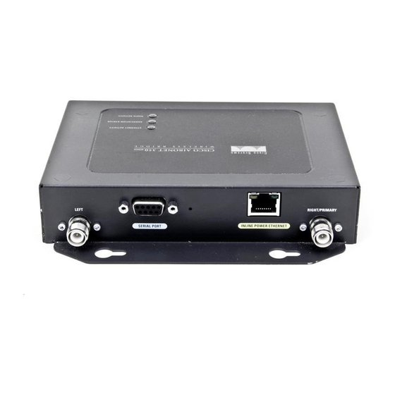
Page 37: Using A Terminal Emulator
Connect a 9-pin, male-to-female, straight-through serial cable (provided with your bridge) to the COM Step 1 port on a computer and to the RS-232 serial port on the back of the bridge. Figure 3-3 shows the location of the bridge’s serial port. Cisco Aironet 350 Series Bridge Hardware Installation Guide OL-1412-01... - Page 38 IM AR Y O N LI N E PO W ER ET H ER N RS-232 9-pin serial extension cable to PC COM port Step 2 Open the terminal emulator. Cisco Aironet 350 Series Bridge Hardware Installation Guide 3-10 OL-1412-01...
- Page 39 Step 8 Note Cisco recommends assigning a static IP address to your bridge to simplify network management and to prevent delays in receiving an address through DHCP. To assign a static IP address to your bridge, select None from the Configuration Server Protocol menu and enter the IP address for the bridge in the Default IP Address field.
- Page 40 Custom—Press c and then press Enter to select this setting. The bridge will use the settings you • enter on the Root Radio Hardware page. Chapter 3 of the Cisco Aironet 350 Series Bridge Software Configuration Guide describes the Root Radio Hardware page.
- Page 41 • non-Aironet 802.11—Press no and then press Enter to select this setting. Select this setting if the bridge is operating as an access point and there are non-Cisco Aironet devices on your wireless LAN. Press sn and then press Enter to select SNMP Admin. Community. Enter an SNMP community name.
- Page 42 A root access point cannot associate with another root access point or root bridge. When you select Root Access Point, the bridge’s Spanning-Tree Protocol (STP) function is disabled. Cisco Aironet 350 Series Bridge Hardware Installation Guide 3-14 OL-1412-01...
- Page 43 Custom—Press c and then press Enter to select this setting. The bridge will use the settings you • enter on the Root Radio Hardware page. Chapter 3 of the Cisco Aironet 350 Series Bridge Software Configuration Guide describes the Root Radio Hardware page.
-
Page 44: Default Basic Settings
Press Enter when you have completed your entry. You can define other SNMP communities with User Management. The “Security Setup” section in Chapter 3 of the Cisco Aironet 350 Series Bridge Software Configuration Guide describes User Management. Press ap and press Enter to apply your basic settings. If you changed the Role in Radio Network setting, Step 15 your bridge reboots. -
Page 45: Chapter 4 Troubleshooting
C H A P T E R Troubleshooting This chapter provides troubleshooting procedures for basic problems with the bridge. For the most up-to-date, detailed troubleshooting information, refer to the Cisco TAC website at http://www.cisco.com/tac. Select Wireless LAN under Top Issues. Sections in this chapter include: •... -
Page 46: Checking The Top Panel Indicators
At least one wireless client device is green associated with the unit. Blinking Not associated with a wireless device. green Check the device SSID and WEP encryption key settings. Verify that all wireless devices have identical settings. Cisco Aironet 350 Series Bridge Hardware Installation Guide OL-1412-01... -
Page 47: Checking Basic Settings
0987654321 and select it as the transmit key, you must also set WEP Key 3 on the bridge to exactly the same value. Refer to the “Security Setup” section in Chapter 3 of the Cisco Aironet 350 Series Bridge Software Configuration Guide for instructions on setting the bridge’s WEP keys. -
Page 48: Encryption Enabled/Disabled
Typically, high-gain antennas compress the radiation pattern in some directions to increase the gain in other directions. Cisco Aironet 350 Series Bridge Hardware Installation Guide OL-1412-01... -
Page 49: Resetting To The Default Configuration
IP address, and the SSID. If you do not need to reset the entire configuration, use the Configuration Reset buttons on the System Configuration Setup page in the web-browser interface. Consult the Cisco Aironet 350 Series Bridge Software Configuration Guide for more information on the reset buttons in the web-browser interface. - Page 50 Chapter 4 Troubleshooting Resetting to the Default Configuration Cisco Aironet 350 Series Bridge Hardware Installation Guide OL-1412-01...
-
Page 51: Appendix
A P P E N D I X Translated Safety Warnings This appendix provides translations of the safety warnings that appear in this publication. These translated warnings apply to other documents in which they appear in English. Cisco Aironet 350 Series Bridge Hardware Installation Guide OL-1412-01... -
Page 52: Explosive Device Proximity Warning
Varning! Använd inte den trådlösa nätverksenheten i närheten av oskyddade tändhattar eller i en explosiv miljö om inte enheten modifierats för att kunna användas i sådana sammanhang. Cisco Aironet 350 Series Bridge Hardware Installation Guide OL-1412-01... -
Page 53: Lightning Activity Warning
Read the installation instructions before you connect the system to its power source. Waarschuwing Raadpleeg de installatie-aanwijzingen voordat u het systeem met de voeding verbindt. Varoitus Lue asennusohjeet ennen järjestelmän yhdistämistä virtalähteeseen. Cisco Aironet 350 Series Bridge Hardware Installation Guide OL-1412-01... -
Page 54: Circuit Breaker (15A) Warning
Vérifier qu'un fusible ou qu'un disjoncteur de 120 V alt., 15 A U.S. maximum (240 V alt., 10 A international) est utilisé sur les conducteurs de phase (conducteurs de charge). Cisco Aironet 350 Series Bridge Hardware Installation Guide A-10 OL-1412-01... - Page 55 (överströmsskydd). Kontrollera att säkring eller överspänningsskydd används på fasledarna (samtliga strömförande ledare) för internationellt bruk max. 240 V växelström, 10 A (i USA max. 120 V växelström, 15 A). Cisco Aironet 350 Series Bridge Hardware Installation Guide A-11 OL-1412-01...
-
Page 56: Installation And Grounding Warning
Per un’accurata installazione e sistemazione al suolo dell’antenna, fare riferimento ai codici nazionali e locali (es. U.S.A.: NFPA 70, Codice Elettrico Nazionale, Articolo 810, Canada: Codice Elettrico Canadese, Sezione 54). Cisco Aironet 350 Series Bridge Hardware Installation Guide A-12 OL-1412-01... - Page 57 För riktig installation och jordning av antennen, undersök landets and den lokala omgivningens koder (t.ex. U.S.: NFPA 70, National Electrical Code, Article 810, Canada: Canadian Electrical Code, Section 54). Cisco Aironet 350 Series Bridge Hardware Installation Guide A-13 OL-1412-01...
- Page 58 Appendix A Translated Safety Warnings Installation and Grounding Warning Cisco Aironet 350 Series Bridge Hardware Installation Guide A-14 OL-1412-01...
-
Page 59: Appendix
A P P E N D I X Declarations of Conformity and Regulatory Information This appendix provides declarations of conformity and regulatory information for Cisco Aironet access points. This appendix contains the following sections: Manufacturers Federal Communication Commission Declaration of Conformity Statement •... -
Page 60: Manufacturers Federal Communication Commission Declaration Of Conformity Statement
The Part 15 radio device operates on a non-interference basis with other devices operating at this Caution frequency. Any changes or modification to said product not expressly approved by Cisco could void the user’s authority to operate this device. Cisco Aironet 350 Series Bridge Hardware Installation Guide... -
Page 61: Department Of Communications - Canada
êáé ôéò ëïéðÝò äéáôÜîåéò ôçò Ïäçãßáò 1999/5/EÊ. Français: Cet appareil est conforme aux exigencies essentialles et aux autres dispositions pertinantes de la Directive 1999/5/EC. Íslenska: Þessi búnaður samrýmist lögboðnum kröfum og öðrum ákvæðum tilskipunar 1999/5/ESB. Cisco Aironet 350 Series Bridge Hardware Installation Guide OL-1412-01... - Page 62 This equipment is intended to be used in all EU and EFTA countries. Outdoor use may be restricted to Note certain frequencies and/or may require a license for operation. For more details, contact Cisco Corporate Compliance. Combinations of power levels and antennas resulting in a radiated power level of above 100 mW eirp are...
-
Page 63: Declaration Of Conformity For Rf Exposure
Guidelines for Operating Cisco Aironet Access Points and Bridges in Japan This section provides guidelines for avoiding interference when operating Cisco Aironet access points and bridges in Japan. These guidelines are provided in both Japanese and English. Japanese Translation... -
Page 64: Declaration Of Conformity Statements
All the Declaration of Conformity statements related to this product can be found at the following URL: http://www.ciscofax.com Declaration of Conformity Statement for European Union Countries The Declaration of Conformity statement for the European Union countries is listed below: Cisco Aironet 350 Series Bridge Hardware Installation Guide OL-1412-01... -
Page 65: Declaration Of Conformity
Date & Place of Issue: 12 August 2002 - Paris Signature: Frank Dewachter - Manager Corporate Compliance EMEA 11, rue Camille Desmoulins - 92782, Issy Les Moulineaux Cedex 9 France DofC 112808 rev3 Cisco Aironet 350 Series Bridge Hardware Installation Guide OL-1412-01... - Page 66 Appendix B Declarations of Conformity and Regulatory Information Declaration of Conformity Statements Cisco Aironet 350 Series Bridge Hardware Installation Guide OL-1412-01...
-
Page 67: Appendix
This appendix provides basic antenna information. The following topics are covered in this section: Antenna System General Antenna and Safety Tips Lightning Arrestors Antenna Cable Antenna Types Cisco Aironet 350 Series Bridge Hardware Installation Guide OL-1412-01... -
Page 68: Antenna System
In outdoor environments, obstructions such as trees, vehicles, buildings, and hills must be considered. Distance is a primary factor when using bridge-to-bridge communications; however, coverage area also becomes important when you are using wireless client devices to communicate with the bridge. Cisco Aironet 350 Series Bridge Hardware Installation Guide OL-1412-01... -
Page 69: General Antenna And Safety Tips
LAN device near a good source of ground, such as structural steel or the ground on an electrical panel, and ground the arrestor using one of those grounds. Figure 1 shows the connectors on the arrestor and the proper placement of the ground lug. Cisco Aironet 350 Series Bridge Hardware Installation Guide OL-1412-01... -
Page 70: Antenna Cable
Antenna Types Cisco Aironet offers several different styles of antennas in the 2.4 GHz range. Each antenna has been FCC-approved for use with the bridge. The antennas provide omnidirectional, directional, or diversity coverage and support various communication distances. Antennas are available with different gain ratings and coverage areas. -
Page 71: Basic Antenna Alignment
Click OK on the bottom of the screen, then on the pop-up message click OK to update the selections. On the bridge Setup screen, click Associations to view the Association Table screen and verify that the destination bridge is listed in the Association Table. Cisco Aironet 350 Series Bridge Hardware Installation Guide OL-1412-01... -
Page 72: Performing A Link Test
Enter 1000 in the Link Test Count entry box to increase the number of packets used. Step 3 Click Link Test to begin the link test operation. Step 4 When the link test completes, the results are displayed on a pop-up status screen. Cisco Aironet 350 Series Bridge Hardware Installation Guide OL-1412-01... - Page 73 3-16 Express Setup page 3-16 configuration default examples resetting to defaults guidelines, installation summary Configuration Server Protocol 3-6, 3-11, 3-13 Configuring the Bridge viii configuring the bridge hardware installation guide Cisco Aironet 350 Series Bridge Hardware Installation Guide IN-1 OL-1412-01...
- Page 74 Repeater Access Point explosive device proximity warning Root Access Point installation warning root unit lightning activity warning network configuration examples power injector warning Note viii serial cable, connecting 3-10 site surveys Cisco Aironet 350 Series Bridge Hardware Installation Guide IN-2 OL-1412-01...
- Page 75 3-11 using terminal type, default 3-16 Troubleshooting description viii troubleshooting basic settings indicator lights out of range reset to defaults unpacking the bridge voltage range warnings Cisco Aironet 350 Series Bridge Hardware Installation Guide IN-3 OL-1412-01...
- Page 76 Index Cisco Aironet 350 Series Bridge Hardware Installation Guide IN-4 OL-1412-01...