Advertisement
MICROWAVE HOOD COMBINATION
INSTALLATION INSTRUCTIONS
This product is suitable for use above electric or gas cooking products up to 36" (91.4 cm) wide.
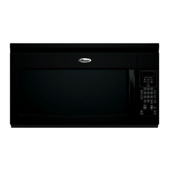
These installation instructions cover different models. The appearance of your particular model may differ slightly from the
illustration in these installation instructions.
NOTES:
•
Proper installation is the responsibility of the installer.
•
Product failure due to improper installation is not covered under the warranty.
Table of Contents
MICROWAVE HOOD COMBINATION SAFETY..............................J
INSTALLATIONREQUIREMENTS ................................................... 2
Tools and Parts............................................................................... 2
Location Requirements................................................................... 2
Product Dimensions ....................................................................... 3
Electrical Requirements.................................................................. 3
INSTALLATIONINSTRUCTIONS ..................................................... 4
Remove Mounting Plate ................................................................. 4
Rotate Blower Motor....................................................................... 4
Locate Wall Stud(s)......................................................................... 6
Mark RearWall................................................................................ 7
Drill Holes in RearWall.................................................................... 7
Attach Mounting Plate to Wall........................................................ 8
Prepare Upper Cabinet ................................................................... 8
Install DamperAssembly ................................................................ 9
Install the Microwave Oven ............................................................ 9
Complete Installation.................................................................... 10
VENTING DESIGN SPECIFICATIONS............................................ 1 1
ASSISTANCE ................................................................................... 12
Replacement Par_s....................................................................... 12
Accessories ................................................................................... 12
MICROWAVE HOOD COMBINATION SAFETY
Your safety and the safety of others are very important.
We have provided many important safety messages in this manual and on your appliance. Always read and obey all safety
messages.
This is the safety alert symbol.
This symbol alerts you to potential hazards that can kill or hurt you and others.
All safety messages will follow the safety alert symbol and either the word "DANGER" or "WARNING."
These words mean:
You can be killed or seriously injured if you don't immediately
follow
instructions.
You can be killed or seriously injured if you don't follow
instructions.
All safety messages will tell you what the potential hazard is, tell you how to reduce the chance of injury, and tell you what can
happen if the instructions are not followed.
IMPORTANT: Read Installation Instructions thoroughly before beginning installation. Save Installation Instructions for local house
inspector's use.
8206587
Advertisement
Table of Contents

Related Manuals for Whirlpool MH1160XSB


Summary of Contents for Whirlpool MH1160XSB
- Page 1 MICROWAVE HOOD COMBINATION INSTALLATION INSTRUCTIONS This product is suitable for use above electric or gas cooking products up to 36" (91.4 cm) wide. These installation instructions cover different models. The appearance of your particular model may differ slightly from the illustration in these installation instructions.
-
Page 2: Installationrequirements
INSTALLATIONREQUIREMENTS Loccion } Ieqt i emenfs Tools Needed Check the opening where the microwave oven will be installed. The location must provide: Gather the required tools and parts before starting installation. Read and follow the instructions provided with any tools •... -
Page 3: Electrical Requirements
Installation Dimensions NOTE: The grounded 3 prong outlet must be inside the upper cabinet. See "Electrical Requirements" section. Electrical Shock Hazard Plug into a grounded 3 prong outlet. 30" (76.2 cm) typical* Do not remove ground prong. 12" (30.5 cm) min. 14"... -
Page 4: Installationinstructions
INSTALLATIONINSTRUCTIONS i otek{ Mokx' The microwave oven is set for recirculation installation. For wall or NOTE: To avoid possible damage to the work surface, cover the work surface. roof venting, changes must be made to the venting system. 1. Remove any remaining contents from the microwave oven NOTE: Skip this section if you are using recirculation installation. -
Page 5: Rotate Blower Motor
Rotate blower motor 180 ° so that exhaust ports face the back Rotate blower motor so that exhaust ports face the top of of microwave oven, and lower it back into the microwave microwave oven, and flat sides of blower motor face back of oven. -
Page 6: Install The Microwave Oven
Lx}c@e S 'ud(s) NOTE: If no wall studs exist within the cabinet opening, do not 1. Using a stud finder, locate the edges of the wall stud(s) within install the microwave oven, the opening. See illustrations in "Possible Wall Stud Configurations," 2. - Page 7 Wall Venting Installation Only The microwave oven must be installed on a minimum of I wall Centerline Upper cabinet bottom stud, preferably 2, using a minimum of I lag screw, preferably 2. 1. Using measuring tape, find and clearly mark the vertical centerline of the opening.
- Page 8 Wall Stud at One Corner Hole (Figure 3) A csc! Mou l>ee o W(:s NOTE: Secure the mounting plate to the wall at both bottom 1. With the support tabs of the mounting plate facing forward, corner hobs drilled into the wall studs and/or drywall using either insert a 1/4-20 x 3"...
- Page 9 5. Cut the 11/2"(3.8 cm) diameter hole at the circular shaded area "G" on the template. This hole is for the power supply cord. ns xs the Mc o7 'e Oven NOTE: If upper cabinet is metal, the supply cord bushing needs to be installed around the supply cord hole, as shown.
- Page 10 NOTE: Ifmicrowave oven does notneed tobeadjusted, skip 2. Connect vent to damper assembly. steps 7-9. 7. Ifadjustment isrequired, rotate m icrowave oven downward. Using 2 ormore people, liftmicrowave oven offofmounting plate, a nd setaside onaprotected surface. 8. Loosen m ounting plate screws. Adjust mounting plate and retighten screws.
- Page 11 VENTING DESIGN SPECIFICATIONS This section is intended for architectural designer and builder/ Rectangular to Round Transition contractor reference only. NOTE: The minimum 3" (7.6 cm) clearance must exist between NOTES: the top of the microwave oven and the rectangular to round transition piece so that the damper can open freely and fully.
-
Page 12: Assistance
Recommended Vent Length ASSISTANCE A 31/4"x 10" (8.3 x 25.4 cm) rectangular or 6" (15.2 cm) round vent should be used. Call your authorized dealer or service center. When you call, you will need the microwave oven model number and serial number. The total length of the vent system including straight vent, Both numbers can be found on the model and serial number elbow(s), transitions and wall or roof caps must not exceed the...