Intel IXM5414E - Blade Server Ethernet Switch Module SBCEGBESW User Manual
Blade server ethernet switch module
Hide thumbs
Also See for IXM5414E - Blade Server Ethernet Switch Module SBCEGBESW:
- Installation manual (38 pages)
Table of Contents
Advertisement
Quick Links
Download this manual
See also:
Installation Manual
Advertisement
Table of Contents
Troubleshooting

Related Manuals for Intel IXM5414E - Blade Server Ethernet Switch Module SBCEGBESW


Summary of Contents for Intel IXM5414E - Blade Server Ethernet Switch Module SBCEGBESW
- Page 1 Intel® Blade Server Ethernet Switch Module IXM5414E: Installation and User’s Guide A Guide for Technically Qualified Assemblers of Intel® Identified Subassemblies/Products C66107-004...
-
Page 3: Table Of Contents
4 Switch Management and Operating Concepts ......19 Intel® Blade Server Ethernet Switch Module IXM5414E overview ... . 19 Switch module management and control . - Page 4 Appendix A RJ-45 Pin Specifications ........227 Appendix B Cable Lengths .
-
Page 5: Safety
Safety Before installing this product, read the Safety Information. Antes de instalar este produto, leia as Informações de Segurança. Pred instalací tohoto produktu si prectete prírucku bezpecnostních instrukcí. Læs sikkerhedsforskrifterne, før du installerer dette produkt. Lees voordat u dit product installeert eerst de veiligheidsvoorschriften. Ennen kuin asennat tämän tuotteen, lue turvaohjeet kohdasta Safety Information. - Page 6 Antes de instalar este producto, lea la información de seguridad. Läs säkerhetsinformationen innan du installerar den här produkten. Statement 1: DANGER Electrical current from power, telephone, and communication cables is hazardous. To avoid a shock hazard: • Do not connect or disconnect any cables or perform installation, maintenance, or reconfiguration of this product during an electrical storm.
- Page 7 Statement 2: xxCAUTION: When laser products (such as CD-ROMs, DVD drives, fiber optic devices, or transmitters) are installed, note the following: • Do not remove the covers. Removing the covers of the laser product could result in exposure to hazardous laser radiation. There are no serviceable parts inside the device. •...
- Page 8 Statement 3: ≥ 18 kg (39.7 lb) ≥ 32 kg (70.5 lb) ≥ 55 kg (121.2 lb) xxCAUTION: Use safe practices when lifting. Statement 4: xxCAUTION: If you install a strain-relief bracket option over the end of the power cord that is connected to the device, you must connect the other end of the power cord to an easily accessible power source.
- Page 9 Statement 6: DANGER Overloading a branch circuit is potentially a fire hazard and a shock hazard under certain conditions. To avoid these hazards, ensure that your system electrical requirements do not exceed branch circuit protection requirements. Refer to the Statement 7: xxCAUTION: Hazardous voltage, current, and energy levels might be present.
-
Page 11: Introducing The Intel® Blade Server Ethernet Switch Module Ixm5414E
Setting up and installing your switch module • Configuring your switch module For installation details, see Chapter 2 “Installing and Removing the Intel® Blade Server Ethernet Switch Module IXM5414E” on page 9. For additional information, see the instructions in your appropriate server board chassis publications. -
Page 12: Related Publications
In addition to this Installation and User’s Guide, the Intel® Server Boards and Server Chassis Safety Information is included with your switch module. This multilingual publication is provided in PDF on the Resource CD. -
Page 13: Notices And Statements Used In This Book
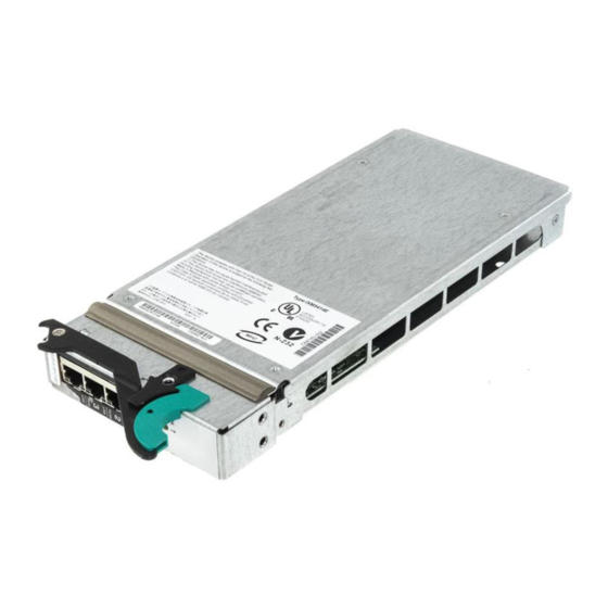
The blue color on components and labels indicates touch points where a component can be gripped, a latch can be moved, and so on. The following illustration shows the major components of your switch module. NOTE The illustrations in this document may differ slightly from your hardware. Intel® Blade Server Ethernet Switch Module IXM5414E... -
Page 14: Specifications And Features
— Media Access Control (MAC) address learning: Automatic update. Supports 3584 MAC address. — Forwarding table age time: Maximum age: 10 to 1,000,000 seconds. Default is 300 seconds — Support for 128 concurrent VLANs — Switch Topology: Star Intel® Blade Server Ethernet Switch Module IXM5414E... - Page 15 RFC 2868 - RADIUS Attributes for Tunnel Protocol Support • RFC 2869 - RADIUS Extensions • RFC 2869bis - RADIUS Support for Extensible Authentication Protocol (EAP) – Advanced Layer 2 Functionality: • Broadcast Storm Recovery • Multicast Storm Recovery Intel® Blade Server Ethernet Switch Module IXM5414E...
- Page 16 — Command Line Interface (CLI) with the following features – Scripting capability – Command completion – Context sensitive help – Multi-session Telnet Server — RFC 854 - Telnet — RFC 855 - Telnet Option Intel® Blade Server Ethernet Switch Module IXM5414E...
- Page 17 Draft-ietf-secsh-dh-group-exchange-04 - Diffie-Hellman Group Exchange for the SSH Transport Layer Protocol — MIBs Supported – Switching MIBs • RFC 1213 - MIB-II • RFC 1493 - Bridge MIB • RFC 1643 - Ethernet-like MIB Intel® Blade Server Ethernet Switch Module IXM5414E...
- Page 18 UTP Category 5 (100 meters maximum) – EIA/TIA-568 100-ohm STP (100 meters maximum) — 1000BASE-T – UTP Category 5e (100 meters maximum) – UTP Category 5 (100 meters maximum) – EIA/TIA-568B 100-ohm STP (100 meters maximum) Intel® Blade Server Ethernet Switch Module IXM5414E...
-
Page 19: Installing And Removing The Intel® Blade Server Ethernet Switch Module
2 Installing and Removing the Intel® Blade Server Ethernet Switch Module IXM5414E The following illustration shows the I/O module bay locations in the SBCE platform. Attention: To maintain proper system cooling, each I/O module bay must contain either a module or a filler module;... -
Page 20: Installation Guidelines
Connection 3 (from all blade server interface options in the SBCE) Connection 4 (from all blade server interface options in the SBCE) For additional information, see the Intel® Blade Server Chassis SBCE : Installation and User’s Guide on the Resource CD. -
Page 21: Installing The Ixm5414E Switch Module
There are no serviceable parts inside these components. If you suspect a problem with one of these parts, contact a service technician. The following illustrations show how to install a switch module in the rear of the SBCE platform. Intel® Blade Server Ethernet Switch Module IXM5414E... - Page 22 1. Review the information in “Safety” on page v and in “Installation guidelines” on page 10. 2. Remove the acoustic attenuation module, if installed, from the rear of the SBCE platform. The following illustrations show how to remove the module from the SBCE platform. Intel® Blade Server Ethernet Switch Module IXM5414E...
- Page 23 12. Attach any cables required by the switch module. For the location of the connectors on the SBCE platform, see Intel® Server Chassis SBCE Installation and User’s Guide on the Resource 13. Replace the acoustic attenuation module if you removed it in Step 2. The following illustration shows how to replace the acoustic attenuation module in the SBCE platform.
-
Page 24: Removing The Ixm5414E Switch Module
3. For the SBCE platform, pull the release latch toward the side of the switch module as shown in the illustration below. The module moves out of the I/O module bay about 0.64 cm (0.25 inch). SBCE Intel® Blade Server Ethernet Switch Module IXM5414E... - Page 25 6. If you placed another switch module in the I/O module bay, reconnect any cables that you unplugged in Step 2. 7. Replace the acoustic attenuation module option if you removed it in step 1. Intel® Blade Server Ethernet Switch Module IXM5414E...
- Page 26 Intel® Blade Server Ethernet Switch Module IXM5414E...
-
Page 27: Information Panel Leds And External Ports
3 Information Panel LEDs and External Ports This chapter describes the information panel and LEDs (also known as indicators) on the Intel® Blade Server Ethernet Switch Module IXM5414E. This chapter also identifies the external ports on the information panel. Information panel The information panel of the IXM5414E switch module consists of LEDs and four external 1000BASE-T ports, as shown in the following illustration. - Page 28 Mbps port. When this LED blinks on a port, it indicates that data is being received or transmitted (that is, activity is occurring) on that port. The blink frequency is proportional to the amount of traffic on that port. Intel® Blade Server Ethernet Switch Module IXM5414E...
-
Page 29: Switch Management And Operating Concepts
4 Switch Management and Operating Concepts This chapter discusses many of the concepts and features used to manage the Intel® Blade Server Ethernet Switch Module IXM5414E and the concepts necessary to understand how it functions. In addition, this chapter explains many important points regarding these features. -
Page 30: Switch Module Management And Control
(see Chapter 5 “Web-Based Network Management” on page 41 for detailed information). The Web browser interface can be invoked from the management and configuration utility program, along with the Telnet interface that provides a Command Line Interface Intel® Blade Server Ethernet Switch Module IXM5414E... -
Page 31: Ip Addresses And Snmp Community Names
MAC address is located on one side of the switch module, on the same label as the serial number, as shown in the following illustration. NOTE The MAC address is also located on a separate label on the information panel under the external Ethernet port connectors. Intel® Blade Server Ethernet Switch Module IXM5414E... - Page 32 This trap indicates that the switch module has been turned on and initialized such that software settings are reconfigured and hardware systems are restarted. A cold start is different from a factory reset in that configuration settings saved to Intel® Blade Server Ethernet Switch Module IXM5414E...
-
Page 33: Port Mirroring
10/100/1000 Mbps external ports, or one of the fourteen internal blade server ports. The target port is where you will connect a monitoring/troubleshooting device, such as a sniffer or an RMON probe. The target port must be one of the four 10/100/1000 Mbps external ports. Intel® Blade Server Ethernet Switch Module IXM5414E... -
Page 34: Switching Concepts
Switching concepts This section introduces the concepts and protocols relevant to the switching functionality of the Intel® Blade Server Ethernet Switch Module IXM5414E. Packet forwarding The switch module uses a forwarding table to store the information that it collects about the location of devices on the network. - Page 35 IEEE 802.1D compatibility mode operation, but can be configured to use the algorithm and protocols defined in IEEE 802.1w instead. Where this document refers to IEEE 802.1D, you should be aware that the reference is to IEEE 802.1D compatibility mode. Intel® Blade Server Ethernet Switch Module IXM5414E...
- Page 36 VLAN. Any port can be configured as either tagging or untagging. The untagging feature of IEEE 802.1Q VLANs enables VLANs to work with legacy switches that do not recognize VLAN tags in packet Intel® Blade Server Ethernet Switch Module IXM5414E...
- Page 37 “Tagging and untagging” on page 29. For more information about port states, see “IEEE 802.1D STP port states” on page 259 and “IEEE 802.1w STP port states” on page 260. Intel® Blade Server Ethernet Switch Module IXM5414E...
- Page 38 The EtherType and VLAN ID are inserted after the MAC source address, but before the original EtherType/Length or Logical Link Control. Because the packet is now longer than it was originally, the cyclic redundancy check (CRC) must be recalculated. Intel® Blade Server Ethernet Switch Module IXM5414E...
-
Page 39: Port Vlan Id
If the packet is not tagged with VLAN information, the ingress port will tag the packet with its own PVID as a VID (if the port is configured to accept untagged packets) and pass it to the forwarding function. Intel® Blade Server Ethernet Switch Module IXM5414E... -
Page 40: Static Mac Filtering
Registration occurs only on ports that receive the GARP PDU containing a declaration or withdrawal. De-registration occurs only if all GARP participants connected to the same LAN segment as the port withdraw the declaration. Intel® Blade Server Ethernet Switch Module IXM5414E... - Page 41 (i.e. VLAN membership) throughout the network. GVRP allows both end stations and the switch module to issue and revoke declarations relating to membership in VLANs. The Intel® Blade Server Ethernet Switch Module IXM5414E complies with the specifications in IEEE 802.1D and IEEE 802.1Q.
- Page 42 Allowing switches to snoop IGMP packets is one way to solve this problem. The switch uses the information in the IGMP packets as they are being forwarded throughout the network to determine which segments should receive packets directed to particular group addresses. Intel® Blade Server Ethernet Switch Module IXM5414E...
-
Page 43: Static Lags
IGMP group in response to an IGMP Leave Group message. (LAG) The Intel® Blade Server Ethernet Switch Module IXM5414E supports Link Aggregation (LAG), or port trunking. Port trunks (aggregated ports) can be used to increase the bandwidth of a network connection or to ensure fault recovery.You can configure up to two trunk connections (combining... - Page 44 System startup might therefore result in a new IP address for a client computer, but neither the user nor the network administrator has to take any action in the configuration process. Intel® Blade Server Ethernet Switch Module IXM5414E...
-
Page 45: Security
A port may take one of two states: Controlled Traffic will only be exchanged if the port is in the Authorized state. Uncontrolled Allows the uncontrolled exchange of EAP over IEEE 802 LANs (EAPoL) PDUs between the Authenticator and Supplicant. Intel® Blade Server Ethernet Switch Module IXM5414E... -
Page 46: Local Authentication
Secure SHell (SSH). Table 2. Secure Shell Feature Details SSH Feature Component Type Connection Type Interactive Login Authentication Method Password Ciphers 3DES-CBC • • Blowfish-CBC • Twofish128-CBC • AES128-CBC Intel® Blade Server Ethernet Switch Module IXM5414E... - Page 47 Table 3. Secure Sockets Layer Details SSL Feature Component Type Protocols Secured HTTP Ciphers • • • 3DES Hash Algorithms • • SHA-1 Key Exchange Methods Diffie-Hellman • • SSL Protocol Versions • TLS 1.0 • SSL 3.0 Intel® Blade Server Ethernet Switch Module IXM5414E...
-
Page 48: Quality Of Service (Qos)
Quality of Service (QoS) The Quality of Service (QoS) features of the Intel® Blade Server Ethernet Switch Module IXM5414E allow you to allocate network bandwidth according to the needs of the network users. This section will give you an overview of the methods available. - Page 49 IP Protocol Number An ‘implicit deny’ rule is added to the end of every ACL. This means that if a packet does not match any of the rules you have defined it will be dropped. Intel® Blade Server Ethernet Switch Module IXM5414E...
- Page 50 Intel® Blade Server Ethernet Switch Module IXM5414E...
-
Page 51: Web-Based Network Management
This chapter describes how to use the Web-based network management module to access and configure the internal switching software. Important: Before you configure your Intel® Blade Server Ethernet Switch Module IXM5414E, be sure that the management modules in your SBCE platform are properly configured. In addition, to access and manage your switch module from an external environment, you might need to enable certain features, such as the external ports and external management over all ports. -
Page 52: Getting Started
IP address the switch module acquired from a Dynamic Host Configuration Protocol (DHCP) server when the switch module was turned on or reset. Depending on which browser you are using, a Login hyperlink displays: Intel® Blade Server Ethernet Switch Module IXM5414E... - Page 53 The User name and Password fields are case sensitive. To increase system security, set a password after you log onto the system for the first time and be sure to store the new password in a safe location. Intel® Blade Server Ethernet Switch Module IXM5414E...
- Page 54 All of these main menu options (except Logout) have sub-menus, some of which have further sub- menus, as shown below. All of the Web-based switch module management features are accessed from these sub-menus and are described in the remainder of this chapter. Intel® Blade Server Ethernet Switch Module IXM5414E...
-
Page 55: System
For more details on the information displayed, see “System description” on page 48. System The System menu provides access to the following panels and menus: • Address Resolution Protocol (ARP) cache • Inventory information • Configuration • Forwarding database • Logs Intel® Blade Server Ethernet Switch Module IXM5414E... -
Page 56: Arp Cache
The identification of the port being used for the connection. Click the Refresh button to retrieve and display the database again, starting with the first entry in the table. Inventory information This panel displays inventory information for the switch. Intel® Blade Server Ethernet Switch Module IXM5414E... - Page 57 Base MAC Address The burned-in, universally administered, MAC address of this switch, displayed as six two-digit hexadecimal numbers separated by hyphens. Software Version The release.version.maintenance number of the code currently running on the switch. Intel® Blade Server Ethernet Switch Module IXM5414E...
-
Page 58: System Description
System description • Network connectivity • Telnet • User accounts • Login configuration • Login session • Login summary • User login System description This panel displays and allows configuration of system information. Intel® Blade Server Ethernet Switch Module IXM5414E... -
Page 59: Network Connectivity
Once you have established in-band connectivity, you can change the IP information using any of the following: • Terminal interface via telnet or SSH connections • SNMP-based management • Web-based management Intel® Blade Server Ethernet Switch Module IXM5414E... - Page 60 If you run the applet you will be able to click on the picture of the switch to select configuration screens instead of using the navigation tree at the left side of the screen. The factory default is Enabled. Intel® Blade Server Ethernet Switch Module IXM5414E...
-
Page 61: User Accounts
User accounts Use this panel to reconfigure an existing user account or to create a new one. This panel is only available for the user with Read/Write privileges, herein referred to as admin. Intel® Blade Server Ethernet Switch Module IXM5414E... - Page 62 If the value is set to Read-only, the SNMPv3 user will only be able to retrieve parameter information. The SNMPv3 access mode may be different from the CLI and Web access mode. Intel® Blade Server Ethernet Switch Module IXM5414E...
- Page 63 GUEST, are assigned to a pre-configured list named defaultList, which you may not delete. All newly created users are also assigned to the defaultList until you specifically assign them to a different list. Intel® Blade Server Ethernet Switch Module IXM5414E...
-
Page 64: Login Session
(including the default user) for system login or IEEE 802.1X port access control. You can only use this button if you have Read/Write access. Login session This panel displays the details for all user login sessions. Intel® Blade Server Ethernet Switch Module IXM5414E... - Page 65 Session Time The total session time. Click the Refresh button to update the information on the page. Login summary This panel displays a list of all users set up for each authentication login list. Intel® Blade Server Ethernet Switch Module IXM5414E...
-
Page 66: User Login
Configuration screen. This list is used to authenticate the users for port access, using the IEEE 802.1X protocol. Click the Refresh button to update the information on the page. User login Use this panel to assign a user to an authentication login list. Intel® Blade Server Ethernet Switch Module IXM5414E... - Page 67 Click the Apply button to cause the changes made on this screen to take effect on the switch click. If you want the switch to retain the new values across a power cycle, you must perform a save. Intel® Blade Server Ethernet Switch Module IXM5414E...
-
Page 68: Forwarding Database
This panel displays the forwarding database entries. You can specify a filter to determine which addresses are displayed or a MAC address to display the table entry for the requested MAC address (and all entries following the requested MAC address). Intel® Blade Server Ethernet Switch Module IXM5414E... - Page 69 The ifIndex of the MIB interface table entry associated with the port. Status The status of this entry. The possible values are: Learned The entry was learned by observing the source MAC addresses of incoming traffic, and is currently in use. Intel® Blade Server Ethernet Switch Module IXM5414E...
-
Page 70: Message Log
This panel displays the message log maintained by the switch. The message log contains system trace information that records non-critical problems. Message log information is not retained across a switch reset and wraps after 512 entries. Intel® Blade Server Ethernet Switch Module IXM5414E... -
Page 71: Event Log
The log can hold at least 2,000 entries (the actual number depends on the platform and OS), and is erased when an attempt is made to add an entry after it is full. The event log is preserved across system resets. Intel® Blade Server Ethernet Switch Module IXM5414E... - Page 72 This menu provides access to port configuration and display options, including: • Configuration • Summary • Mirroring Configuration Use this panel to enable or disable one or more ports. The port will only participate in the network when it is enabled. Intel® Blade Server Ethernet Switch Module IXM5414E...
- Page 73 For normal and LAG ports this field will be blank. Otherwise the possible values are: Probe Monitoring port, participating in Port Mirroring. Following is how this panel displays when the port type is Probe. Intel® Blade Server Ethernet Switch Module IXM5414E...
- Page 74 The factory default is auto. You can only use this menu for the external ports. Physical Status Indicates the port speed and duplex mode. This field only displays if the Link Status is Up. Intel® Blade Server Ethernet Switch Module IXM5414E...
- Page 75 Click the Apply button to update the switch with the values you entered. If you want the switch to retain the new values across a power cycle you must perform a save. Summary This panel displays the status of all ports in the box. Intel® Blade Server Ethernet Switch Module IXM5414E...
- Page 76 Root Port, Designated Port, Alternate Port, Backup Port, Master Port or Disabled Port. Admin Mode Displays the port administration mode. The port must be Enabled in order for it to be allowed into the network. The factory default is Enabled. Intel® Blade Server Ethernet Switch Module IXM5414E...
- Page 77 Indicates whether or not a trap will be sent when link status changes. The factory default is Enabled. ifIndex Indicates the ifIndex of the interface table entry associated with this port. Mirroring This panel displays the port mirroring information for the switch module. Intel® Blade Server Ethernet Switch Module IXM5414E...
- Page 78 SNMP This menu provides access to the following Simple Network Management Protocol (SNMP) options: • Community configuration • Trap receiver configuration • Trap receiver summary • Supported MIBs Intel® Blade Server Ethernet Switch Module IXM5414E...
-
Page 79: Community Configuration
The default values for the remaining four community names are blank. Community names in the SNMP community table must be unique. If you make multiple entries using the Intel® Blade Server Ethernet Switch Module IXM5414E... -
Page 80: Trap Receiver Configuration
IP addresses in the SNMP trap receiver table must be unique. If you make multiple entries using the same IP address, the first entry is retained and processed. All duplicate entries are ignored. Intel® Blade Server Ethernet Switch Module IXM5414E... - Page 81 This panel displays information about SNMP trap receivers. Trap messages are sent across a network to an SNMP Network Manager. These messages alert the manager to events occurring within the switch or on the network. Up to six trap receivers are supported at the same time. Intel® Blade Server Ethernet Switch Module IXM5414E...
- Page 82 Indicates whether traps are currently Enabled for this community: Enable Traps will be sent. Disable Traps will not be sent. Supported Management Information Bases (MIB) This panel displays a list of all the MIBs supported by the switch. Intel® Blade Server Ethernet Switch Module IXM5414E...
-
Page 83: Switch Detailed
This menu provides access to menu options that display various switch statistics, including: • Switch detailed • Switch summary • Port detailed • Port summary Switch detailed This panel displays detailed statistics for all CPU traffic. Intel® Blade Server Ethernet Switch Module IXM5414E... - Page 84 The number of inbound packets that were chosen to be discarded even though no errors had been detected that would prevent their being deliverable to a higher-layer protocol. One possible reason for discarding a packet could be to free up buffer space. Transmitted Intel® Blade Server Ethernet Switch Module IXM5414E...
- Page 85 The number of VLANs that have been created and then deleted on this switch module since the last reboot. Time Since Counters Last Cleared: The elapsed time in days, hours, minutes and seconds since the statistics for this port were last cleared. Intel® Blade Server Ethernet Switch Module IXM5414E...
-
Page 86: Switch Summary
The total number of packets transmitted from the switch module without an error occurring. Broadcast Packets Transmitted The total number of packets that higher-layer protocols requested to be transmitted to the broadcast address, including those that were discarded or not sent. Intel® Blade Server Ethernet Switch Module IXM5414E... -
Page 87: Port Detailed
Use this field to select the port for which to display statistics. Click the down arrow to display the list of ports from which to choose. ifIndex This object indicates the ifIndex of the interface table entry associated with this port. Packets Received: Intel® Blade Server Ethernet Switch Module IXM5414E... - Page 88 Total Packets Received with MAC Errors Total Packets Received with MAC Errors The total number of inbound packets that contained errors that prevented them from being delivered to a higher-layer protocol. Intel® Blade Server Ethernet Switch Module IXM5414E...
- Page 89 511 octets in length (excluding framing bits but including FCS octets). Packets Transmitted 512-1023 Octets The total number of packets (including bad packets) transmitted that were between 512 and 1023 octets in length (excluding framing bits but including FCS octets). Intel® Blade Server Ethernet Switch Module IXM5414E...
- Page 90 Single Collision Frames The number of successfully transmitted packets which encountered exactly one collision. Multiple Collision Frames The number of successfully transmitted packets which encountered more than one collision. Intel® Blade Server Ethernet Switch Module IXM5414E...
- Page 91 Time Since Counters Last Cleared The elapsed time in days, hours, minutes and seconds since the statistics for this port were last cleared. The following displays the bottom of the panel, showing the buttons available. Intel® Blade Server Ethernet Switch Module IXM5414E...
-
Page 92: Port Summary
Click the Refresh button to refresh the data on the screen with the present state of the data in the switch. Port summary This panel displays a summary of the statistics for a specified port. Intel® Blade Server Ethernet Switch Module IXM5414E... - Page 93 The elapsed time in days, hours, minutes and seconds since the statistics for this port were last cleared. Click the Clear Counters button to clear all the counters, resetting all statistics for this port to default values. Intel® Blade Server Ethernet Switch Module IXM5414E...
-
Page 94: System Utilities
The switch uses the stored configuration to initialize the switch. You are prompted to confirm that the reset should proceed. A successful reset is indicated by the LEDs on the switch. Intel® Blade Server Ethernet Switch Module IXM5414E... -
Page 95: Reset Configuration To Defaults
Click the Reset button to reset all user passwords to the factory defaults (since only the ADMIN can set passwords, this is blank). You are prompted to confirm that the password reset should proceed. Intel® Blade Server Ethernet Switch Module IXM5414E... -
Page 96: Download File To Switch
Download file to switch Use this panel to configure the information needed to download a file to the switch. Intel® Blade Server Ethernet Switch Module IXM5414E... - Page 97 The last row of the table is used to display information about the progress of the file transfer. The screen will refresh automatically until the file transfer completes. The Intel® Blade Server Ethernet Switch Module IXM5414E software supports the use of a TFTP client. The TFTP client path statement requirement is server dependent. A path statement is generally required to setup the TFTP client;...
-
Page 98: Upload File From Switch
Click the Start File Transfer button to apply any changes made to the fields and initiate the upload. Click the Apply button to send the updated screen to the switch; this does not perform the file upload. This command is valid only when the transfer mode is TFTP. Intel® Blade Server Ethernet Switch Module IXM5414E... -
Page 99: Trap Manager
SNMP Trap Receivers and a message will be written to the trap log. Cold and warm start traps are always enabled. Intel® Blade Server Ethernet Switch Module IXM5414E... -
Page 100: Trap Log
Click the Apply button to send the updated screen to the switch and cause the changes to take effect on the switch. These changes will not be retained across a power cycle unless a save is performed. Trap log This panel displays the entries in the trap log. Intel® Blade Server Ethernet Switch Module IXM5414E... -
Page 101: Switching
Switching This menu provides access to all the switch-related processing screens. Options on this menu are: • VLAN • Filters • GARP • IGMP snooping • Link aggregation • Multicast forwarding database Intel® Blade Server Ethernet Switch Module IXM5414E... - Page 102 4094 (ID 1 is reserved for the default VLAN). VLAN Name A string associated with this VLAN as a convenience. It can be up to 16 alphanumeric characters long, including blanks. The default is blank. VLAN ID 1 Intel® Blade Server Ethernet Switch Module IXM5414E...
- Page 103 Participation Use the pull-down menu to configure the degree of participation of this port in this VLAN. The permissible values are: Include This port is always a member of this VLAN. This is equivalent to registration fixed in the IEEE 802.1Q standard. Intel® Blade Server Ethernet Switch Module IXM5414E...
- Page 104 What type of VLAN this is. A VLAN can be: • the Default VLAN (VLAN ID = 1). • a static VLAN, one that you have created. • a Dynamic VLAN, one that is created by GVRP registration. Intel® Blade Server Ethernet Switch Module IXM5414E...
-
Page 105: Port Configuration
The factory default is 1. Acceptable Frame Types Specify how you want the port to handle untagged and priority tagged frames. If you select VLAN only, the port will discard any untagged or priority tagged frames Intel® Blade Server Ethernet Switch Module IXM5414E... - Page 106 Port VLAN ID for this port. With either option, VLAN tagged frames are forwarded in accordance with the IEEE 802.1Q VLAN specification. Port Priority The VLAN Port Priority that this port will assign to untagged frames received on this port. Intel® Blade Server Ethernet Switch Module IXM5414E...
-
Page 107: Reset Configuration
MAC Filter This is the list of MAC address and VLAN ID pairings for all configured filters. To change the port mask(s) for an existing filter, select the entry you want to change. Intel® Blade Server Ethernet Switch Module IXM5414E... -
Page 108: Mac Filter Summary
Click the Apply button to update the switch with the values on the screen. If you want the switch to retain the new values across a power cycle you must perform a save. MAC filter summary This panel displays the Static MAC filtering information. Intel® Blade Server Ethernet Switch Module IXM5414E... - Page 109 The factory default is Disabled. Switch GMRP Indicates whether the GMRP administrative mode for this switch is Enabled or Disabled. The factory default is Disabled. Port Indicates which port is associated with the fields on this line. Intel® Blade Server Ethernet Switch Module IXM5414E...
-
Page 110: Switch Configuration
60 seconds). The factory default is 1000 centiseconds (10 seconds). Switch configuration Use this panel to Enable or Disable GVRP and GMRP for this switch. Note: It can take up to 10 seconds for GARP configuration changes to take effect. Intel® Blade Server Ethernet Switch Module IXM5414E... - Page 111 Port configuration Use this panel to specify GARP detail for one or all ports. Note: It can take up to 10 seconds for GARP configuration changes to take effect. Intel® Blade Server Ethernet Switch Module IXM5414E...
- Page 112 The Leave All Period Timer is set to a random value in the range of LeaveAllTime to 1.5*LeaveAllTime. The timer is specified in centiseconds. Enter a number between 200 and 6000 (2 to 60 seconds). The factory default is 1000 Intel® Blade Server Ethernet Switch Module IXM5414E...
-
Page 113: Igmp Snooping
Enter a value between 1 and 3600 seconds. The default is 10 seconds. The configured value must be less Intel® Blade Server Ethernet Switch Module IXM5414E... -
Page 114: Interface Configuration
Disabled. Click the Apply button to update the switch with the values you enter. If you want the switch to retain the new values across a power cycle you must perform a save. Intel® Blade Server Ethernet Switch Module IXM5414E... - Page 115 Link Trap Enables or Disables link trap notifications for the specified LAG. Administrative Mode This field Enables or Disables the specified LAG(s). Link Status Indicates whether the Link is Up or Down. Intel® Blade Server Ethernet Switch Module IXM5414E...
- Page 116 The logical port identifier of the LAG, in the format lag.port. LAG Name The name of this LAG. Admin Mode The administrative mode. The factory default is Enabled. Link State Indicates whether the link is Up or Down. Intel® Blade Server Ethernet Switch Module IXM5414E...
-
Page 117: Mfdb Table
Entries may contain data for more than one protocol. Options on this menu are: • MFDB table • GMRP table • IGMP snooping table • Stats MFDB table Use this panel to display entries from the MFDB. Intel® Blade Server Ethernet Switch Module IXM5414E... -
Page 118: Gmrp Table
This panel displays the GMRP entries in the MFDB table. MAC Address A MAC address and VLAN pair for which the switch has forwarding and/or filtering information. The format is two two-digit hexadecimal numbers Intel® Blade Server Ethernet Switch Module IXM5414E... -
Page 119: Igmp Snooping Table
The list of interfaces that are designated for forwarding (Fwd:) and filtering (Flt:). Click the Clear Entries button to tell the IGMP Snooping component to delete all of its entries from the multicast forwarding database. Intel® Blade Server Ethernet Switch Module IXM5414E... -
Page 120: Spanning Tree
This menu provides access to spanning tree-related configuration and status screens. Menu options are: • Switch configuration/status • CST configuration/status • CST port configuration/status • Statistics Switch configuration/status Use this panel to configure the spanning tree parameters for the switch. Intel® Blade Server Ethernet Switch Module IXM5414E... - Page 121 If you want the switch to retain the new values across a power cycle you must perform a save. Common Spanning Tree (CST) configuration/status Use this panel to configure or display the bridge parameters for the Spanning Tree Algorithm. Intel® Blade Server Ethernet Switch Module IXM5414E...
- Page 122 Time Since Topology Change The time in seconds since the spanning tree topology last changed. Topology Change Count Number of times the spanning tree topology has changed. Intel® Blade Server Ethernet Switch Module IXM5414E...
- Page 123 CST port configuration/status Use this panel to configure a particular port within the CST. Port Select one of the physical or LAG interfaces from the pull-down menu. Intel® Blade Server Ethernet Switch Module IXM5414E...
- Page 124 Point-to-point MAC Derived value of the point-to-point status. CST Regional Root Bridge Identifier of the CST Regional Root. It is made up using the bridge priority and the base MAC address of the bridge. Intel® Blade Server Ethernet Switch Module IXM5414E...
-
Page 125: Class Of Service
Number of Rapid Reconfiguration BPDUs transmitted from the selected port. Click the Refresh button to update the screen with the most recent data. Class of service This menu contains one option – 802.1p priority mapping. Intel® Blade Server Ethernet Switch Module IXM5414E... -
Page 126: Security
If you want the switch to retain the new values across a power cycle you must perform a save. Security This menu describes the web menus used to configure and manage the security features of the Intel® Blade Server Ethernet Switch Module IXM5414E. These features include: •... - Page 127 If you want the switch to retain the new values across a power cycle you must perform a save. Port configuration Use this panel to begin the initialization or the reauthentication sequence on the selected port. Intel® Blade Server Ethernet Switch Module IXM5414E...
- Page 128 The quiet period range is 0 to 65535. A quiet period value of 0 means that the authenticator state machine will never acquire a supplicant. The default value is 60. Intel® Blade Server Ethernet Switch Module IXM5414E...
-
Page 129: Port Status
If you want the switch to retain the new values across a power cycle you must perform a save. Port status This panel displays the details of the IEEE 802.1X configuration parameters for the specified port. Intel® Blade Server Ethernet Switch Module IXM5414E... - Page 130 Displays the configured transmit period for the selected port. The transmit period is the value, in seconds, of the timer used by the authenticator state machine on the specified port to determine when to send an EAPOL EAP Request/Identity frame to Intel® Blade Server Ethernet Switch Module IXM5414E...
- Page 131 Displays the PAE functionality of the selected port. Possible values are Authenticator or Supplicant. Authenticator PAE State Displays the current state of the authenticator PAE state machine. Possible values are: • Initialize • Disconnected • Connecting • Authenticating • Authenticated Intel® Blade Server Ethernet Switch Module IXM5414E...
- Page 132 This panel displays a summary of the IEEE 802.1X configuration parameters for all switch ports. Port The port whose settings are displayed in the associated table row. Control Mode Displays the configured control mode for the port. Possible values are: Intel® Blade Server Ethernet Switch Module IXM5414E...
- Page 133 Displays the authorization status of the specified port. The possible values are Authorized and Unauthorized. Click the Refresh button to update the information on the page. Statistics This panel displays the IEEE 802.1X statistics for the specified port. Intel® Blade Server Ethernet Switch Module IXM5414E...
- Page 134 The number of EAP response/identity frames that have been received by this authenticator. EAP Response Frames Received The number of valid EAP response frames (other than response/identity frames) that have been received by this authenticator. Intel® Blade Server Ethernet Switch Module IXM5414E...
- Page 135 Users Select the user name to be configured. Login Selects the login list to be associated with the selected user. All configured login lists are displayed. Intel® Blade Server Ethernet Switch Module IXM5414E...
-
Page 136: Port Access Privileges
Click the Apply button to send the updated screen to the switch and cause the changes to take effect on the switch. Port access summary This panel displays IEEE 802.1X port security information about locally configured users. Intel® Blade Server Ethernet Switch Module IXM5414E... - Page 137 Therefore, the maximum delay in receiving a response from the RADIUS application equals the sum of maximum retransmit times the timeout for all configured servers. If the RADIUS request was generated by a user login Intel® Blade Server Ethernet Switch Module IXM5414E...
-
Page 138: Server Configuration
Click the Apply button to send the updated screen to the switch and cause the changes to take effect on the switch. Server configuration Use this panel to configure the IP address of a RADIUS server. Up to three servers can be configured for each RADIUS client. Intel® Blade Server Ethernet Switch Module IXM5414E... - Page 139 Read/Write users. If you want the switch to retain the new values across a power cycle you must perform a save. Click the Refresh button to update the information on the page. Intel® Blade Server Ethernet Switch Module IXM5414E...
-
Page 140: Radius Statistics
The number of RADIUS Access-Response packets received from unknown addresses. Click the Refresh button to update the information on the page. Server statistics This panel displays the statistics for a configured RADIUS server. Intel® Blade Server Ethernet Switch Module IXM5414E... - Page 141 Bad Authenticators The number of RADIUS Access-Response packets received from this server, including packets with invalid authenticators or signature attributes. Intel® Blade Server Ethernet Switch Module IXM5414E...
- Page 142 The Secret is applied only if this box is checked. If the box is not checked, anything entered in the Secret field has no affect and is not retained. This field is only displayed if the user has Read/Write access. Intel® Blade Server Ethernet Switch Module IXM5414E...
- Page 143 Displays the number of RADIUS Accounting-Request packets sent not including retransmissions. Accounting Retransmissions Displays the number of RADIUS Accounting-Request packets retransmitted to this RADIUS accounting server. Accounting Responses Displays the number of RADIUS packets received on the accounting port from this server. Intel® Blade Server Ethernet Switch Module IXM5414E...
-
Page 144: Clear Statistics
The Secure Sockets Layer (SSL) encryption protocol provides a means of abstracting an encrypted connection between two stations, allowing HTTP to operate securely on an open network. This menu provides access to the Secure HTTP configuration panel. Configuration Use this panel to configure Secure HTTP variables. Intel® Blade Server Ethernet Switch Module IXM5414E... - Page 145 Click the Apply button to send the updated screen to the switch and have the changes take effect on the switch If you want the switch to retain the new values across a power cycle you must perform a save. Intel® Blade Server Ethernet Switch Module IXM5414E...
-
Page 146: Secure Shell
Click the Download Host Keys button to link to the File Transfer page to download the Host Key(s). NOTE To download SSH key files SSH must be administratively Disabled and there can be no active SSH sessions Intel® Blade Server Ethernet Switch Module IXM5414E... -
Page 147: Qos
ACL applies using the Configuration screen. You specify the rules for the ACL using the ACL Rule Configuration screen. ACL menu options are: • Configuration • Summary • Rule configuration Configuration Use this panel to create an ACL. Intel® Blade Server Ethernet Switch Module IXM5414E... - Page 148 If you want the switch to retain the new values across a power cycle you must perform a save. Click the Delete button to remove the currently selected ACL from the switch configuration. Intel® Blade Server Ethernet Switch Module IXM5414E...
-
Page 149: Rule Configuration
Clicking one of the configure buttons shown on that screen will display a third screen allowing you to configure the match criterion you selected. Intel® Blade Server Ethernet Switch Module IXM5414E... - Page 150 Match Every to False for the other match criteria to be visible. Click the Apply button to save your choice and return to the main screen, or click the Cancel button to exit without saving a change. Intel® Blade Server Ethernet Switch Module IXM5414E...
- Page 151 Enter an IP address using dotted-decimal notation to be compared to a packet's destination IP address as a match criteria for the selected ACL rule. Source IP Mask Enter the IP Mask in dotted-decimal notation to be used with the Source IP address value. Intel® Blade Server Ethernet Switch Module IXM5414E...
- Page 152 • Bandwidth profile configuration • Bandwidth profile summary • Traffic class configuration • Traffic class summary • Interface allocation summary Bandwidth profile configuration Use this panel to create a bandwidth allocation profile. Intel® Blade Server Ethernet Switch Module IXM5414E...
- Page 153 Click the Delete button to delete the selected bandwidth allocation profile from the system. Bandwidth profile summary This panel displays the bandwidth allocation information for all bandwidth profiles on the switch. Intel® Blade Server Ethernet Switch Module IXM5414E...
-
Page 154: Traffic Class Configuration
Maximum Bandwidth Displays the sum of the maximum allowable bandwidth for all bandwidth profiles configured on this interface. Traffic class configuration Use this panel to create a traffic class. Intel® Blade Server Ethernet Switch Module IXM5414E... - Page 155 This field associates a bandwidth allocation profile with a Traffic Class. The sum of the bandwidth allocation profile minimum bandwidth of all Traffic Classes associated with the same interface should not exceed the total bandwidth of the interface. Intel® Blade Server Ethernet Switch Module IXM5414E...
- Page 156 Bandwidth Profile The bandwidth allocation profile associated with this Traffic Class in the form “name-id (min-max Mbps)”. This field is blank when there is no bandwidth allocation profile associated with this traffic class. Intel® Blade Server Ethernet Switch Module IXM5414E...
-
Page 157: Logout
When you’re finished and want to exit the program simply close your browser. If you click the Logout option on the main menu you will get the message, “Please close your browser to logout.” Intel® Blade Server Ethernet Switch Module IXM5414E... - Page 158 Intel® Blade Server Ethernet Switch Module IXM5414E...
-
Page 159: Updating The Ethernet Switch Software
6 Updating the Ethernet Switch Software Two types of software run on the Ethernet switch module: the software image and the Micro- Controller Unit (MCU) code. You can update both the software image and the code, using either the switch module's CLI commands through a Telnet session, or by using the switch module's web interface. -
Page 160: Upgrading The Switch Software
Make sure that this software is installed on your server; then, download the software image or the MCU code from the Intel Web site into a directory on your TFTP server. Enable the TFTP server and set the directory that contains the image as the default directory. - Page 161 • In the TFTP File Name field, enter filename IXM54_nnn.opr where nnn is the software sequence number of the new switch software. 6. Click Start File Transfer to download the new switch software Intel® Blade Server Ethernet Switch Module IXM5414E...
-
Page 162: Resetting And Restarting The Switch Module
1. From the I/O Module Tasks menu, click Management / Advanced Management. 2. Select the I/O-module bay on which the software update is installed. 3. From the I/O Module Tasks menu, click Power/Restart. Intel® Blade Server Ethernet Switch Module IXM5414E... - Page 163 I/O-module bay that contains the Ethernet switch module that you just installed; then, note the corresponding level of the software for the switch module. Make sure that the latest switch operating-system software is correctly installed on the Ethernet switch module. Intel® Blade Server Ethernet Switch Module IXM5414E...
- Page 164 Intel® Blade Server Ethernet Switch Module IXM5414E...
-
Page 165: Command Line Interface Management
7 Command Line Interface Management Your Intel® Blade Server Ethernet Switch Module IXM5414E supports a management interface that you can use to set up and control your device over the network using the TCP/IP Telnet protocol. You can use this facility to perform the same network management functions that you can perform using the Web Interface. - Page 166 This is used to identify a logical interface – a Link Aggregation Group or a VLAN. You enter a name and number separated by a period, for example: lag.3 identifies LAG 3 vlan.2 identifies VLAN 2 Intel® Blade Server Ethernet Switch Module IXM5414E...
-
Page 167: Special Characters
Ctrl-Z return to root command prompt Tab, <SPACE> command-line completion Exit go to next lower command prompt execute the most recent command execute the nth most recent command Intel® Blade Server Ethernet Switch Module IXM5414E... -
Page 168: Remotely Managing The Ixm5414E Switch Module
This chapter contains additional instructions for configuring the switch module for this mode of operation. The two previously described modes are only applicable to the Intel® Blade Server Ethernet Switch Module IXM5414E. The management module can only be remotely accessed through the 10/100 Mbps Ethernet port on the management module. - Page 169 (and all other configuration settings) that you might have entered and return the switch module to its original state at the time of purchase. Intel® Blade Server Ethernet Switch Module IXM5414E...
-
Page 170: Ixm5414E Switch Module System Commands
System configuration commands • System description commands • System utility commands • Trap management commands Later sections describe the commands that you use to configure and manage the various protocols running on the switch. Intel® Blade Server Ethernet Switch Module IXM5414E... -
Page 171: System Commands
The format is a two byte hexadecimal VLAN ID number followed by a six byte MAC address with each byte separated by hyphens, for example 00-01-00- 23-45-67-89-AB. Port The physical interface on which the MAC address was learned. Intel® Blade Server Ethernet Switch Module IXM5414E... -
Page 172: Inventory Information
The burned-in universally administered MAC address of this switch. Software Version The release.version.maintenance number of the code currently running on the switch. Operating System The operating system currently running on the switch. Network Processing Element Identifies the network processor hardware. Intel® Blade Server Ethernet Switch Module IXM5414E... -
Page 173: Port Commands
Use this command to enable or disable one or more ports. The port will only participate in the network when it is enabled. Default enable Format config port adminmode <port/listofports/all> <enable/disable> config port autoneg Use this command to enable or disable automatic negotiation on one or more ports. Default enable Intel® Blade Server Ethernet Switch Module IXM5414E... - Page 174 The interface number of the physical port or LAG whose information is displayed on the line. Type If not blank, this field indicates that this port is a special type of port. The possible values are: Monitoring port, participating in Port Mirroring. Intel® Blade Server Ethernet Switch Module IXM5414E...
- Page 175 It is not necessary to disable port mirroring before modifying the probe and mirrored ports. Default disable Format config mirroring mode <enable/disable> Intel® Blade Server Ethernet Switch Module IXM5414E...
- Page 176 IP mask before being compared to this IP address. Note that if the IP mask is set to 0.0.0.0, an IP address of 0.0.0.0 matches all IP addresses. The default value is “0.0.0.0”. The parameter <name> is the applicable community name, and may be up to 16 alphanumeric characters. Default 0.0.0.0 Intel® Blade Server Ethernet Switch Module IXM5414E...
- Page 177 IP addresses. The default value is 0.0.0.0. Client IP Mask The mask that will be ANDed with the requesting entity's IP address before comparison with the Client IP address. If the result matches the Client IP address Intel® Blade Server Ethernet Switch Module IXM5414E...
- Page 178 SNMP communities are separate and distinct. IP Address The IP address that receives SNMP traps from the switch for this trap receiver community. Status Indicates whether traps are currently enabled for this community Intel® Blade Server Ethernet Switch Module IXM5414E...
-
Page 179: System Configuration
TCP port 80. Disabling access takes effect immediately on all interfaces. Default enable Format config network webmode <enable/disable> Intel® Blade Server Ethernet Switch Module IXM5414E... - Page 180 Use this command to configure the number of simultaneous Telnet and Secure Shell (SSH) sessions that can be established. A value of 0 indicates that no Telnet session can be established. The range is 0 to 5. Default Format config telnet maxsessions <0-5> Intel® Blade Server Ethernet Switch Module IXM5414E...
- Page 181 IDs can be defined. Format config users add <name> config users delete Use this command to remove a user account. Format config users delete <name> NOTE The admin user account cannot be deleted. Intel® Blade Server Ethernet Switch Module IXM5414E...
- Page 182 Use this command to display the configured user names and their settings. This command is only available for the user with Read/write privileges. Format show users info User Name The name the user will use to login using the serial port, Telnet or Web. Intel® Blade Server Ethernet Switch Module IXM5414E...
- Page 183 Total time this session has been connected. System description config prompt Use this command to change the prompt that is displayed when you use the CLI. You may enter up to 64 alphanumeric characters. Format config prompt <system prompt> Intel® Blade Server Ethernet Switch Module IXM5414E...
- Page 184 1023 octets in length (excluding framing bits but including FCS octets). Packets Received 1024-1518 Octets The total number of packets (including bad packets) received that were between 1024 and 1518 octets in length (excluding framing bits but including FCS octets). Intel® Blade Server Ethernet Switch Module IXM5414E...
- Page 185 Frame Check Sequence (FCS) with an integral number of octets. Received Packets Not Forwarded 802.3x Pause Frames Received A count of MAC Control frames received on this interface with an opcode indicating the PAUSE operation. This counter does not increment when the Intel® Blade Server Ethernet Switch Module IXM5414E...
- Page 186 Broadcast Packets Transmitted The total number of packets that higher-level protocols requested be transmitted to a broadcast address, including those that were discarded or not sent. Transmit Errors Intel® Blade Server Ethernet Switch Module IXM5414E...
- Page 187 Generic Attributes Registration Protocol (GARP) layer. GVRP PDUs Transmitted The number of GVRP PDUs transmitted by the GARP layer. GVRP PDUs Failed Registrations The number of times attempted GVRP registrations could not be completed. Intel® Blade Server Ethernet Switch Module IXM5414E...
- Page 188 Received Octets Received The total number of octets of data received by the processor (excluding framing bits but including FCS octets). Packets Received Without Errors Total number of packets received on the network Intel® Blade Server Ethernet Switch Module IXM5414E...
- Page 189 The number of learned and static Forwarding Database Address Table entries currently in use by this switch module. VLAN Entries Maximum VLAN Entries The maximum number of VLANs allowed on the switch module. Intel® Blade Server Ethernet Switch Module IXM5414E...
- Page 190 The number of VLANs currently in the VLAN table on this switch module. Time Since Counters Last Cleared The elapsed time in days, hours, minutes and seconds since the statistics for the switch were last cleared. Intel® Blade Server Ethernet Switch Module IXM5414E...
- Page 191 Database (MFDB). You will be prompted to confirm that you want to issue this command Format clear igmpsnooping clear lag Use this command to clear all LAGs. You will be prompted to confirm that you want to issue this command. Format clear lag Intel® Blade Server Ethernet Switch Module IXM5414E...
- Page 192 Use this command to close the current Telnet connection or reset the current serial connection. If you have any saved configuration changes, you will be prompted to save them. If you logout without issuing a save config command any configuration changes you have made will be lost. Format logout Intel® Blade Server Ethernet Switch Module IXM5414E...
- Page 193 You may specify the file path as part of the file name if the string is less than 31 characters. Otherwise, use the transfer download path command. This command is valid only when the Transfer Mode is TFTP. See transfer download mode. Format transfer download filename <name> Intel® Blade Server Ethernet Switch Module IXM5414E...
- Page 194 Table 5. TFTP Upload Scenarios TFTP Server path TFTP Client path c:\tftp\ blank tftp\ \tftp\ The directory path statement can be cleared by issuing the clear config command. Format transfer upload path <path> Intel® Blade Server Ethernet Switch Module IXM5414E...
- Page 195 This command is valid only when the transfer mode is TFTP. See the command, transfer upload mode. The Intel® Blade Server Ethernet Switch Module IXM5414E software supports the use of a TFTP client. The TFTP client path statement requirement is server dependent. A path statement is generally required to setup the TFTP client;...
- Page 196 Cold and warm start traps are always enabled. Format show trapflags Authentication Flag Indicates whether authentication failure traps will be sent (enable) or not (disable). Intel® Blade Server Ethernet Switch Module IXM5414E...
-
Page 197: Switching Configuration Commands
• IGMP snooping commands • Link Aggregation (LAG) commands • MAC filter commands • Mirroring commands • Multicast Forwarding Database (MFDB) commands • Spanning tree commands • Virtual Local Area Network (VLAN) commands Intel® Blade Server Ethernet Switch Module IXM5414E... -
Page 198: Config Garp Gmrp Adminmode
The value applies per port and per GARP participation. The time may range from 200 to 6000 centiseconds. This command has an effect only when GVRP is enabled. Default 1000 centiseconds (10 seconds) Format config garp leavealltimer <port/listofports/all> <200-6000> Intel® Blade Server Ethernet Switch Module IXM5414E... -
Page 199: Config Garp Leavetimer
LeaveAll Time to (1.5*LeaveAll Time). Permissible values are 200 to 6000 centiseconds (2 to 60 seconds) in increments of 1 centisecond (0.01 seconds). The factory default is 1000 centiseconds (10 seconds). Intel® Blade Server Ethernet Switch Module IXM5414E... -
Page 200: Igmp Snooping Commands
This value must be less than the IGMP query interval time value. The range is 1 to 3599 seconds. Default 10 seconds Format config igmpsnooping maxresponse <1-3599> Intel® Blade Server Ethernet Switch Module IXM5414E... -
Page 201: Config Igmpsnooping Mcrtrexpiretime
Use this command to enable or disable the specified LAG(s). The option <all> sets every configured LAG to the same administrative mode setting. Format config lag adminmode <logical port/listofports/all> <enable/disable> Intel® Blade Server Ethernet Switch Module IXM5414E... -
Page 202: Config Lag Create
STP Mode The Spanning Tree Protocol Administrative Mode associated with the LAG. The possible values are: Disable - Spanning tree is disabled for this LAG. Enable - Spanning tree is enabled for this LAG. Intel® Blade Server Ethernet Switch Module IXM5414E... -
Page 203: Mac Filter Commands
Use this command to remove the static MAC filter entry for the given MAC address on the VLAN. The <macaddr> parameter must be specified as a 6-byte hexadecimal number in the format of 00- 12-34-56-78-90. The <vlan> parameter must identify a valid VLAN. Intel® Blade Server Ethernet Switch Module IXM5414E... -
Page 204: Show Macfilter
Dynamic entries are added to the table as a result of a learning process or protocol. Description The text description of this multicast table entry. Interfaces The list of interfaces that are designated for forwarding (Fwd:) and filtering (Flt:). Intel® Blade Server Ethernet Switch Module IXM5414E... -
Page 205: Show Mfdb Staticfiltering
The component that is responsible for this entry in the MFDB. Possible values are IGMP Snooping, GMRP, and Static Filtering. Description The text description of this multicast table entry. Interfaces The list of interfaces that are designated for forwarding (Fwd:) and filtering (Flt:). Intel® Blade Server Ethernet Switch Module IXM5414E... -
Page 206: Spanning Tree Commands
Bridge Priority The priority component of the bridge identifier. Valid values range from 0-61440, in increments of 4096. The lower the number the higher the priority. The factory default is 32768. Intel® Blade Server Ethernet Switch Module IXM5414E... - Page 207 Use this command to display STP settings for the CST. Format show spanningtree cst detailed Bridge Priority The value of the first two octets of the eight octet Bridge ID. Valid values are 0 to 61440. Factory default is 32768. Intel® Blade Server Ethernet Switch Module IXM5414E...
- Page 208 The <port> is the port to be affected. Format show spanningtree cst port detailed <port> Port Identifier The port identifier for this port within the CST. Port Priority The priority of the port within the CST. Intel® Blade Server Ethernet Switch Module IXM5414E...
- Page 209 The role of the specified port within the spanning tree. Link Status The operational status of the link. Possible values are “Up” or “Down”. Link Trap The link trap configuration for the specified interface. Intel® Blade Server Ethernet Switch Module IXM5414E...
- Page 210 Use this command to select which version of the STP will be used. The <version> can be one of the following: • 802.1D - IEEE 802.1D functionality supported: STP BPDUs are transmitted rather than R(Rapid)STP BPDUs • 802.1w - IEEE 802.1w functionality supported: RSTP BPDUs are transmitted rather than STP BPDUs Intel® Blade Server Ethernet Switch Module IXM5414E...
-
Page 211: Config Vlan Create
Use this command to enable or disable multicast storm control for a particular VLAN. If multicast storm control is enabled, storms are controlled by counting the number of multicast packets within a certain time period. If the [packets per second] count limit is exceeded, the packets are discarded. Intel® Blade Server Ethernet Switch Module IXM5414E... -
Page 212: Config Vlan Name
Format config vlan port priority <0-7> <port/listofports/all> config vlan port pvid Use this command to change the VLAN ID that the specified port(s) will assign to untagged frames if untagged frames are accepted. Intel® Blade Server Ethernet Switch Module IXM5414E... -
Page 213: Config Vlan Port Tagging
This is equivalent to registration normal in the IEEE 802.1Q standard. Configured Displays the configured degree of participation of this port in this VLAN. The permissible values are: Intel® Blade Server Ethernet Switch Module IXM5414E... -
Page 214: Show Vlan Port
• the Default VLAN (VLAN ID = 1) • a static VLAN, one that is created using the config vlan create command • a Dynamic VLAN, one that is created by GVRP registration Intel® Blade Server Ethernet Switch Module IXM5414E... -
Page 215: Class Of Service Commands
Format show classofservice 802.1pmapping User Priority The IEEE 802.1p priority number. The range is 0 to 7. Traffic Class Priority Queue The priority queue number. The range is 0 to 7. Intel® Blade Server Ethernet Switch Module IXM5414E... -
Page 216: Security Configuration Commands
Security configuration commands This section describes the commands used to configure and manage the security features of the Intel® Blade Server Ethernet Switch Module IXM5414E. These features include: • Authentication commands • IEEE 802.1X Port-based network access control • Remote Authentication Dial-In User Service (RADIUS) •... -
Page 217: Config Users Login
The authentication login list assigned to the user for IEEE 802.1X port security. IEEE 802.1X commands clear dot1x port stats Use this command to reset the IEEE 802.1X statistics for the specified port(s). Intel® Blade Server Ethernet Switch Module IXM5414E... -
Page 218: Config Dot1X Adminmode
<port> config dot1x port maxrequests Use this command to configure the maximum number of times the authenticator state machine on the specified port will retransmit an Extensible Authentication Protocol Over LANs (EAPOL) EAP Intel® Blade Server Ethernet Switch Module IXM5414E... -
Page 219: Config Dot1X Port Quietperiod
Use this command to configure the value, in seconds, of the timer used by the authenticator state machine on the specified port to timeout the supplicant. The supplicant timeout must be between 1 and 6553. Default Intel® Blade Server Ethernet Switch Module IXM5414E... -
Page 220: Config Dot1X Port Transmitperiod
The timer used by the authenticator state machine on the specified port to determine when to send an EAPOL EAP Request/Identity frame to the supplicant. The value is expressed in seconds and will be between 1 and 65535. Intel® Blade Server Ethernet Switch Module IXM5414E... -
Page 221: Show Dot1X Port Stats
Last EAPOL Frame Source The source MAC address in the most recently received EAPOL frame. EAP Response/ID Frames Received The number of EAP response/identity frames that have been received by the authenticator port. Intel® Blade Server Ethernet Switch Module IXM5414E... -
Page 222: Show Dot1X Port Summary
Use this command to display a summary of the IEEE 802.1X configuration parameters for the switch. Format show dot1x summary Administrative mode Indicates whether authentication control is enabled on the switch. Intel® Blade Server Ethernet Switch Module IXM5414E... - Page 223 The time, in hundredths of a second, between the most recent RADIUS accounting response and the matching accounting request from this RADIUS accounting server. Accounting Requests The number of RADIUS accounting request packets sent to this accounting server, not including retransmissions. Intel® Blade Server Ethernet Switch Module IXM5414E...
- Page 224 RADIUS server. The maxretransmit value is an integer in the range of 1 and 15. Consideration should be given to the maximum delay time when configuring RADIUS maxretransmit and timeout values. If multiple RADIUS servers are configured, the maxretransmit Intel® Blade Server Ethernet Switch Module IXM5414E...
- Page 225 Max Number of Retransmits The maximum number of times a request packet will be retransmitted. Timeout Duration (secs) The timeout value, in seconds, for request retransmissions. Accounting Mode Indicates whether accounting is currently enabled. Intel® Blade Server Ethernet Switch Module IXM5414E...
- Page 226 20 characters or less. Format config radius server secret <ipaddr> show radius server stats Use this command to display the statistics for a configured RADIUS server. Format show radius server stats <ipaddr> Intel® Blade Server Ethernet Switch Module IXM5414E...
- Page 227 The IP address of the authentication server. Port The port used to access the authentication server. Type Indicates whether the server is primary or secondary. Secret configured Indicates whether a secret has been configured for the authentication server. Intel® Blade Server Ethernet Switch Module IXM5414E...
- Page 228 Command is used to enable/disable the SSL for secure HTTP. Default disable Format config http secureserver adminmode <enable\disable> show http info Displays the http settings for the switch. Format show http info Intel® Blade Server Ethernet Switch Module IXM5414E...
-
Page 229: Quality Of Service (Qos) Commands
Indicates whether the HTTP mode is enabled or disabled. Quality of Service (QoS) commands This section describes the commands used to configure and manage the Quality of Service (QoS) features of the Intel® Blade Server Ethernet Switch Module IXM5414E. These features include: • Access Control Lists (ACLs) •... -
Page 230: Config Acl Rule Action
Either this command or the config acl match destl4port keyword command may be used to specify a destination layer 4 port range as a match condition. Format config acl rule match dstl4port range <aclid> <rulenum> <startport> <endport> Intel® Blade Server Ethernet Switch Module IXM5414E... -
Page 231: Config Acl Rule Match Every
4 port range as a match condition. Either command can be used to configure or modify the source layer 4 port range. Format config acl rule match srcl4port keyword <aclid> <rulenum> <portkey> Intel® Blade Server Ethernet Switch Module IXM5414E... -
Page 232: Show Acl Detailed
Displays the number of rules that are associated with this ACL. Interface(s) Displays the interfaces associated with this ACL. Direction Displays the packet filtering direction for the ACL on the interface. The possible values displayed are inbound and outbound. Intel® Blade Server Ethernet Switch Module IXM5414E... - Page 233 Use this command to display the bandwidth allocation information for all bandwidth allocation profiles in the system. Format show bwprovisioning bwallocation summary Bandwidth Allocation Profile Name Displays the user-defined name of this bandwidth allocation profile. Intel® Blade Server Ethernet Switch Module IXM5414E...
- Page 234 Use this command to configure the priority for this traffic class. The <weight> parameter will be a value between 1 and 1024. Default Format config bwprovisioning trafficclass weight <name> <weight> Intel® Blade Server Ethernet Switch Module IXM5414E...
- Page 235 Displays the interface to which this traffic class is attached. VLAN ID Displays the Virtual Local Area Network (VLAN) ID with which this traffic class is associated. Weight Displays the weight of this traffic class. Intel® Blade Server Ethernet Switch Module IXM5414E...
- Page 236 Bandwidth Allocation Profile Displays the bandwidth allocation profile associated with this traffic class. This field is blank when there is no bandwidth allocation profile associated with this traffic class. Intel® Blade Server Ethernet Switch Module IXM5414E...
-
Page 237: Appendix A Rj-45 Pin Specifications
Appendix A RJ-45 Pin Specifications The four external Ethernet ports of this switch module are auto-configuring and will work with straight-through or crossover cables when connected to other Ethernet equipment. Review the documentation that comes with the product you are connecting to for matching cable pin assignments. - Page 238 Intel® Blade Server Ethernet Switch Module IXM5414E...
-
Page 239: Appendix B Cable Lengths
Appendix B Cable Lengths Use the following table as a guide for the maximum cable lengths: Table 8. Maximum cable lengths Standard Data transmission rate Media type Maximum distance 1000BASE-T 1000 Mbps Category 5e UTP cable 100 meters (328.1 ft) Category 5 UTP cable 100BASE-TX 100 Mbps... - Page 240 Intel® Blade Server Ethernet Switch Module IXM5414E...
-
Page 241: Appendix C Run-Time Switching Software Default Settings
Appendix C Run-time Switching Software Default Settings The following table contains the default settings for the run-time switching software variables. Variables are separated by category and further by sub-headings (listed alphabetically within category). "Default value" is self-explanatory while "Command" lists the CLI command used to change the default setting. - Page 242 SSH2) Secure Socket Layer (SSL) Secure port config http secureport Secure Protocol Both (SSL3 and TLS1) config http secureprotocol Secure Server Mode Disable config http secureserver adminmode Switching VLAN Switching Intel® Blade Server Ethernet Switch Module IXM5414E...
- Page 243 Group Membership 260 seconds config igmpsnooping Interval groupmembershipinterv Interface disable config igmpsnooping interfacemode Maximum response 10 seconds config igmpsnooping time maxresponse MCRT Expiration 0 seconds config igmpsnooping Time mcrtexpiretime Mode Disable config igmpsnooping adminmode Intel® Blade Server Ethernet Switch Module IXM5414E...
- Page 244 Pathcost Auto config spanningtree cst port pathcost Priority config spanningtree cst port priority Port Migration Check Disable config spanningtree port migrationcheck Port Mode Disable config spanningtree port mode System Auto log-out 10 min Intel® Blade Server Ethernet Switch Module IXM5414E...
- Page 245 Network Connectivity IP connectivity 10.90.90.9x config network parms parameters 255.255.255.0 0.0.0.0 IP connectivity None config network protocol protocol Java enable status Enable config network javamode Web enable status Enable config network webmode SNMPcommunit Intel® Blade Server Ethernet Switch Module IXM5414E...
- Page 246 Utilities Transfer Transfer Code transfer Upload/Download upload/download Datatype datatype Transfer Blank transfer upload/download upload/download Filename filename Transfer 0.0.0.0 transfer Upload\Download IP upload\download Address serverip Transfer Blank transfer Upload/download upload/download path Path Trap Management Intel® Blade Server Ethernet Switch Module IXM5414E...
- Page 247 Table 9. Default settings for run-time switching software variables (continued) Sub- Heading heading Variable Default value Command Authenticate Enable config trapflags Trapflags authentication Trapflags Linkmode Enable config trapflags linkmode Trapflags Multiusers Enable config trapflags multiusers Trapflags STP Enable config trapflags stpmode Intel® Blade Server Ethernet Switch Module IXM5414E...
- Page 248 Intel® Blade Server Ethernet Switch Module IXM5414E...
-
Page 249: Appendix D Cli Command Tree
Appendix D CLI Command Tree This appendix presents the CLI command tree used in conjunction with the Intel® Blade Server Ethernet Switch Module IXM5414E. SWITCHING clear config igmpsnooping dot1x port stats pass radius stats stats port switch transfer traplog vlan... - Page 250 802.1mapping dot1x adminmode defaultlogin login port controlmode initialize maxrequests quietperiod reauthenabled reauthenticate reauthperiod servertimeout supptimeout transmitperiod users remove Intel® Blade Server Ethernet Switch Module IXM5414E...
- Page 251 Intel® Blade Server Ethernet Switch Module IXM5414E...
- Page 252 Intel® Blade Server Ethernet Switch Module IXM5414E...
- Page 253 Intel® Blade Server Ethernet Switch Module IXM5414E...
- Page 254 Intel® Blade Server Ethernet Switch Module IXM5414E...
- Page 255 802.1pmappin dot1x port detailed stats summary user summary eventlog forwardingdb agetime learned table garp info interface history http info igmpsnooping inventory loginsession macfilter mfdb gmrp igmpsnooping staticfiltering stats table mirroring msglog network Intel® Blade Server Ethernet Switch Module IXM5414E...
- Page 256 Intel® Blade Server Ethernet Switch Module IXM5414E...
- Page 257 Intel® Blade Server Ethernet Switch Module IXM5414E...
- Page 258 Intel® Blade Server Ethernet Switch Module IXM5414E...
-
Page 259: Appendix E Cli Configuration Examples
Appendix E CLI Configuration Examples This appendix provides examples of using the CLI to configure the Intel® Blade Server Ethernet Switch Module IXM5414E for some key functions. Bridging configuration example This section provides sample CLI commands showing how to configure the Intel® Blade Server Ethernet Switch Module IXM5414E for basic bridging support. - Page 260 You can control how long an address will remain in the database if no traffic is seen from it (the aging timer). config forwardingdb agetime 500 Intel® Blade Server Ethernet Switch Module IXM5414E...
-
Page 261: Ieee 802.1W Configuration Example
IEEE 802.1w configuration example This section shows you how to configure the Intel® Blade Server Ethernet Switch Module IXM5414E to support rapid reconfiguration of the spanning tree topology. The IEEE 802.1w support specified in IEEE 802.1s defines a new configuration algorithm and protocol that provide significantly faster reconfiguration of the spanning tree than the original algorithm and protocol defined in the base IEEE 802.1D standard. -
Page 262: Vlan Configuration Example
VLAN configuration example This section provides sample CLI commands showing how to configure the Intel® Blade Server Ethernet Switch Module IXM5414E to support IEEE 802.1Q VLANs. Configuring VLANs allows you to partition your network on a logical rather than physical basis. The only physical restriction is that both ends of a point-to-point link must be in the same VLAN. -
Page 263: Link Aggregation Configuration Example
Link aggregation configuration example This section provides sample CLI commands showing how to configure the Intel® Blade Server Ethernet Switch Module IXM5414E to support IEEE 802.3ad aggregated links. By defining a Link Aggregation Group (LAG) you can treat multiple physical links between two end-points as one logical link. -
Page 264: Igmp Snooping Configuration Example
IGMP snooping configuration example This section provides sample CLI commands showing how to configure the Intel® Blade Server Ethernet Switch Module IXM5414E to support IGMP Snooping. Activating IGMP Snooping allows you to restrict the forwarding of multicast packets to network segments that need to see the packets. -
Page 265: Access Control List Configuration Example
Access Control List configuration example This section provides sample CLI commands showing how to configure the Intel® Blade Server Ethernet Switch Module IXM5414E to support Access Control Lists (ACLs). ACLs offer one way of adding Quality of Service support to your network. - Page 266 1 config acl interface add ext.3 inbound 1 config acl interface add ext.4 inbound 1 Intel® Blade Server Ethernet Switch Module IXM5414E...
-
Page 267: Appendix F Troubleshooting The Spanning Tree Protocol
Two versions of STP are supported by the Intel® Blade Server Ethernet Switch Module IXM5414E, both of which are defined in IEEE 802.1s. The first version is IEEE 802.1D compatibility mode, set as the factory default. - Page 268 The unique identifier of the bridge that the transmitting bridge currently recognizes as the root bridge • The path cost to the root from the transmitting port • The port identifier of the transmitting port Intel® Blade Server Ethernet Switch Module IXM5414E...
- Page 269 The port is blocked from forwarding or receiving packets. For additional information, see “Discarding state” on page 264. Learning The port is adding addresses to its forwarding database but not yet forwarding packets. For additional information, see “Forwarding state” on page 266. Intel® Blade Server Ethernet Switch Module IXM5414E...
- Page 270 IEEE 802.1w port Active topology port MAC operational state port state state role Disabled Disabled False Discarding Excluded, disabled Disabled Enabled False Discarding Excluded, disabled Excluded, alternate or Blocking Enabled True Discarding backup Intel® Blade Server Ethernet Switch Module IXM5414E...
- Page 271 Forward Delay The Forward Delay can be from 4 to 30 seconds. For IEEE 802.1D operation this is the time that any port on the bridge spends in the learning state while moving from Intel® Blade Server Ethernet Switch Module IXM5414E...
-
Page 272: Illustration Of Stp
However, influencing STP to choose a particular bridge as the root bridge using the Priority setting, or influencing STP to choose a particular port to block using the Port Priority and Port Cost settings, is relatively straightforward. Intel® Blade Server Ethernet Switch Module IXM5414E... - Page 273 LAN 2 LAN 2 The bridge with the lowest bridge ID (bridge A) was elected the root bridge, and the ports were selected to give a high port cost between bridges B and C. Intel® Blade Server Ethernet Switch Module IXM5414E...
- Page 274 Discards packets sent from another port on the bridge for forwarding. • Does not add addresses to its forwarding database. • Receives BPDUs and directs them to the central processing unit (CPU). • Does not transmit BPDUs from the CPU. Intel® Blade Server Ethernet Switch Module IXM5414E...
-
Page 275: Learning State
Learns station location information from the source address of packets and adds this information to its forwarding database. • Receives BPDUs for the CPU and transmits BPDUs from the CPU. The following illustration shows the actions that occur when a port is in the learning state. Intel® Blade Server Ethernet Switch Module IXM5414E... -
Page 276: Forwarding State
Receives BPDUs and directs them to the system CPU. • Transmits BPDUs from the system CPU. • Receives and responds to network management messages. The following illustration shows the actions that occur when a port is in the forwarding state. Intel® Blade Server Ethernet Switch Module IXM5414E... - Page 277 Intel® Blade Server Ethernet Switch Module IXM5414E...
-
Page 278: Disabled State
Discards packets sent from another port on the bridge for forwarding. • Does not add addresses to its forwarding database. • Neither receives nor transmits BPDUs. The following illustration shows the actions that occur when a port is in the disabled state. Intel® Blade Server Ethernet Switch Module IXM5414E... -
Page 279: Troubleshooting Stp
If one port is configured as full duplex and the other port is left in auto-negotiation mode, the second port will end up in half-duplex because ports explicitly configured as half- or full-duplex do not negotiate. Intel® Blade Server Ethernet Switch Module IXM5414E... -
Page 280: Unidirectional Link
Spanning Tree Protocol failure. Root Port 1 Port 1 Port 2 Port 2 Port 1 Port 1 Port 1 Port 1 Designated Port 2 Port 2 Port 2 Port 2 Blocked BPDUs Lost BPDUs Lost Intel® Blade Server Ethernet Switch Module IXM5414E... -
Page 281: Packet Corruption
Disabling the ports one at a time and then checking for the restoration of a user’s connectivity will identify the link that is causing the Intel® Blade Server Ethernet Switch Module IXM5414E... - Page 282 A single discarding port changing to the forwarding state at an inappropriate time can cause a large part of a network to fail. Limiting the number of blocked ports helps to limit the risk of an inappropriate change. Intel® Blade Server Ethernet Switch Module IXM5414E...
- Page 283 VLAN 2. Bridge C is also discarding one port for VLAN 2. Thus, there are three redundant paths between bridges A and B, and two blocked ports per VLAN. This increases the chance of a data loop. Intel® Blade Server Ethernet Switch Module IXM5414E...
- Page 284 In this example, the VLAN definitions are extended to bridges A and B. This gives only a single blocked port per VLAN and enables the removal of all redundant links by removing bridge A or B from the network. Intel® Blade Server Ethernet Switch Module IXM5414E...
-
Page 285: Appendix G Getting Help And Technical Assistance
You can solve many problems without outside assistance by following the troubleshooting procedures that Intel provides in the publications that are provided on the Resource CD that ships with your system and software. The documentation also describes the diagnostic tests that you can perform. - Page 286 Intel® Blade Server Ethernet Switch Module IXM5414E...
-
Page 287: Appendix H Notices
Appendix H Notices Safety and regulatory information NOTE These service procedures are designed to help you isolate problems. They are written with the assumption that you have model-specific training on all computers, or that you are familiar with the computers, functions, terminology, and service information provided in this manual. -
Page 288: General Safety
• Do not touch live electrical circuits with the reflective surface of an inspection mirror. The surface is conductive; such touching can cause personal injury and machine damage. Intel® Blade Server Ethernet Switch Module IXM5414E... - Page 289 Repair or disassemble • Dispose of the battery as required by local ordinances or regulations. xxCAUTION: When laser products (such as CD-ROMs, DVD-ROM drives, fiber optic devices, or transmitters) are installed, note the following: Intel® Blade Server Ethernet Switch Module IXM5414E...
-
Page 290: Regulatory Specifications And Disclaimers
UL/CB to EN60950 3rd Edition International: UL/CB to IEC 60950 3rd Edition UL/CB - EN60 950 3rd Edition UL/CB - EMKO-TSE (74-SEC) 207/94 Australia/New CB Report to IEC 60950, 3rd Edition plus international deviations Zealand: Intel® Blade Server Ethernet Switch Module IXM5414E... - Page 291 Europe (CE Declaration of Conformity): This product has been tested in accordance to, and complies with the Low Voltage Directive (73/23/EEC) and EMC Directive (89/336/EEC). The product has been marked with the CE Mark to illustrate its compliance. Japan EMC Compatibility: Intel® Blade Server Ethernet Switch Module IXM5414E...
- Page 292 “Digital Apparatus”, ICES-003 of the Canadian Department of Communications. BSMI (Taiwan): The BSMI Certification number and the following warning is located on the product safety label which is located visibly on the external chassis. RRL Korea: Intel® Blade Server Ethernet Switch Module IXM5414E...
- Page 293 Remarks: Class A device - operated in a commercial area. Class B device - operated in a residential area. Intel® Blade Server Ethernet Switch Module IXM5414E...
- Page 294 Intel® Blade Server Ethernet Switch Module IXM5414E...