
Related Manuals for Amana RCS511A


Summary of Contents for Amana RCS511A
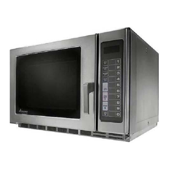
- Page 1 Microwave Oven Service Manual RS511P RS511MB RCS10MPA RCS511A RCS10MPSA RFS511G RFS12MPSA URS511MB RFS12G URS511P URCS511A RFS511SW2A CAUTION BEFORE SERVICING THE UNIT, READ THE SAFETY PRECAUTIONS IN THIS MANUAL.
-
Page 2: Safety Precautions
SAFETY PRECAUTIONS This device is to be serviced only by properly qualified service personnel. Consult the service manual for proper service procedures to assure continued safety operation and for precautions to be taken to avoid possible exposure to excessive microwave energy. PRECAUTIONS TO BE OBSERVED BEFORE AND DURING SERVICING TO AVOID POSSIBLE EXPOSURE TO EXCESSIVE MICROWAVE ENERGY... - Page 3 CONTENTS...
-
Page 4: Specifications
SPECIFICATIONS SPECIFICATIONS SPECIFICA ITEM DESCRIPTION RS511P / RS511MB URS511MB / URS511P MODEL RCS511A / RFS511G URCS511A / RFS511SW2A 230 Volts AC 50 Hz 240 Volts AC 50 Hz Power Requirement Power Requirement Power Requirement Power Requirement 1,60 Watts , , , ,... -
Page 5: Microwave Radiation
CAUTIONS Unlike other appliances, the microwave oven is MICROWAVE RADIATION high-voltage and high-current equipment. Personnel should not be exposed to the Though it is free from danger in ordinary use, microwave energy which may radiate from the extreme care should be taken during repair. magnetron or other microwave generating device if it is improperly used or connection. -
Page 6: Installations
INSTALLATIONS BEFORE YOU BEGIN, READ THE FOLLOWING INSTRUCTIONS COMPLETELY AND CAREFULLY. EARTHING INSTRUCTIONS INSTALLING Green-and-yellow: Earth Blue: Neutral Brown: Live green-and-yellow earth symbol green green-and-yellow blue black brown... -
Page 7: Control Panel
FEATURES Window Door Screen Electronic Control Safety Door Lock System CONTROL PANEL Display Some items in display can be seen but will not glow. Pads TIME ENTRY Use to enter heating time without changing preprogrammed number pads. Pads 1-0 Use to begin heating with preprogrammed times and power levels or to enter times for “Manual Time Entry”... - Page 8 Use to start “Manual Time Entry” program or restart interrupted cooking cycle. Use to advance to next user option. Use to save times and power levels when programming pads. QTY2x Use to automatically increase the programmed time for double quantities. RCS511A / URCS511A...
- Page 9 FEATURES Window Door Screen Electronic Control Safety Door Lock System CONTROL PANEL Display Some items in display can be seen but will not glow. Pads DIAL Use to enter cooking time. QUICK SET Use to begin heating with preprogrammed times and power levels. Use to select power level.
- Page 10 FEATURES Window Door Screen Electronic Control Safety Door Lock System CONTROL PANEL Display Some items in display can be seen but will not glow. Pads TIME ENTRY Use to enter heating time without changing preprogrammed number pads. Pads 1-0 Use to begin heating with preprogrammed times and power levels or to enter times for “Manual Time Entry”...
-
Page 11: Operating Instructions
OPERATING INSTRUCTIONS FEATURES Window Door Screen Electronic Control Safety Door Lock System CONTROL PANEL Display Some items in display can be seen but will not glow. TIME POWER ENTRY LEVEL Pads TIME ENTRY Use to enter heating time without changing preprogrammed number pads. - Page 12 Cooking Displays Cooking Displays Cooking Displays Cooking Displays Shows when power is connected to oven. Open and close door to clear. READY shows when oven control will accept entries. Appears after oven door is opened and closed. 33:33 shows heating time. When more than 1 heating stage is programmed, total time for all stages displays.
- Page 13 Operation Preprogrammed Times and Cook Level CAUTION Pads Heating Pads Pads Heating Heating Times Times Times nterrupting Operation START STOP/RESET START Canceling Mistakes STOP/RESET STOP/RESET Operating Preprogrammed Pads Manual Time Entry TIME ENTRY Operating QTY 2X Pads START...
-
Page 14: Preprogrammed Number Pads
PROGRAMMING Preprogrammed Number Pads Multiple Heating Stages Oven has 10 preprogrammed number pads. Follow Follow instructions below to program oven to perform 3 instructions below to program heating times and power consecutive heating cycles without interruption. levels for customized cooking. 1. -
Page 15: User Options
User Options 4. Press START pad to advance to next option. See table for options. Follow the instructions below to customized the microwave ovenÕs operation. End-of-cycle signal, 5. Press number pad (0,1-3) to change option. maximum heating time and other options can be 6. -
Page 16: Schematic Diagram
SCHEMATIC DIAGRAM 4-10... -
Page 17: Circuit Description
CIRCUIT DESCRIPTION GENERAL DETAILS • A high voltage of approximately 2100 volts AC is generated in the secondary of the high voltage • The low voltage transformer supplies the necessary transformer which is increased by the action of the high voltage to the micom controller when power cord is voltage diode and charging of the high voltage plugged in. -
Page 18: Service Information
SERVICE INFORMATION TOOLS AND MEASURING INSTRUMENTS NECESSARY TOOLS NECESSARY MEASURING INSTRUMENTS Tools normally used for TV servicing are sufficient. ¥ TESTER (VOLTS-DC, AC, Ohmmeter) Standard tools are listed below. ¥ Microwave survey meter ¥ Diagonal pliers - Holaday HI-1500 ¥ Long nose pliers HI-1501 ¥... -
Page 19: Measurement With Outer Case Removed
MEASUREMENT WITH OUTER CASE NOTES WHEN MEASURING REMOVED ¥ Do not exceed meter full scale deflection. ¥ The test probe must be removed no faster than ¥ When you replace the magnetron, measure for 1 inch/sec (2.5 cm/sec) along the shaded area, microwave energy leakage before the outer case is otherwise a false reading may result. -
Page 20: Measurement Of Microwave Power Output
MEASUREMENT OF MICROWAVE POWER OUTPUT • Microwave power output measurement is made with • The microwave power output P in watts is calculated the microwave oven supplied at its rated voltage and from the following formula : operated at its maximum microwave power setting with 4187 x (∆T) a load of (1000±5) g of potable water. - Page 21 Remove choke cover D. PCB ASSEMBLY REMOVAL Remove choke cover 1) Remove the control panel assembly from the cavity. (Refer to control panel assembly removal on previous page.) 2) Remove screws which hold the PCB SUB ASSÕY to the control panel. 3) Disconnect the flat cable from the PCB SUB ASSÕY and take off the PCB SUB ASSÕY PCB Sub Asm...
-
Page 22: Magnetron Removal
F. MAGNETRON REMOVAL G. REMOVING THE STIRRER FAN MOTOR 1) Disconnect the leadwire from the magnetron. 2) Carefully remove the mounting screws holding the 1) Disconnect the leadwire from the stirrer fan motor magnetron and the waveguide. terminals. 3) Remove the magnetron ASS’Y until the tube is 2) Remove the screw securing the stirrer fan motor to clear from the waveguide. -
Page 23: Diode Removal
H. HIGH VOLTAGE TRANSFORMER K. INTERLOCK SYSTEM REMOVAL 1) INTERLOCK MECHANISM The door lock mechanism is a device which has 1) Discharge the high voltage capacitor. been specially designed to eliminate completely 2) Disconnect the leadwire from magnetron, high voltage microwave activity when the door is opened during transformer, and capacitor. -
Page 24: Interlock Continuity Test
INTERLOCK CONTINUITY TEST WARNING : FOR CONTINUED PROTECTION AGAINST EXCESSIVE RADIATION EMISSION, REPLACE ONLY WITH IDENTICAL REPLACEMENT PARTS. TYPE NO. SZM-V 21-FC-93 FOR PRIMARY SWITCH TYPE NO. SZM-V 16-FD-62 OR V-16-2C 25 FOR MONITOR SWITCH TYPE NO. SZM-V 16-FD-63 OR V-16-3C 25 FOR SECONDARY SWITCH B. -
Page 25: Component Test Procedure
COMPONENT TEST PROCEDURE CAUTIONS 1. DISCONNECT THE POWER SUPPLY CORD FROM THE OUTLET WHENEVER REMOVING THE OUTER CASE FROM THE UNIT. PROCEED WITH THE TEST ONLY AFTER DISCHARGING THE HIGH VOLTAGE CAPACITOR AND REMOVING THE WIRE LEADS FROM THE PRIMARY WINDING OF THE HIGH VOLTAGE TRANSFORMER. - Page 26 COMPONENTS TEST PROCEDURE RESULTS Antenna Gasket Chassis Filament NOTE: When testing the magnetron, be sure to install the magnetron gasket in the correct position and be sure that the gasket is in good condition. HIGH VOLTAGE Measure the resistance. Normal: Momentarily indicates CAPACITOR (Ohm-meter scale: Rx1000) several ohms, and...
- Page 27 COMPONENTS TEST PROCEDURE RESULTS Check for continuity of relay 3 an RELAY 3 POWER ohm-meter. LEVEL (Remove wire leads from relay 3 and operate the unit.) 3 sec 9 sec 4 sec 8 sec 5 sec 7 sec 6 sec 6 sec 7 sec 7 sec...
-
Page 28: Trouble Shooting
TROUBLE SHOOTING TROUBLE SHOOTING TROUBLE SHOOTING TROUBLE SHOOTING TROUBLE SHOOTING WHEN YOU GET A COMPLAINT FROM YOUR CUSTOMER, EVALUATE THE COMPLAINT CAREFULLY. IF WHEN YOU GET A COMPLAINT FROM YOUR CUSTOMER, EVALUATE THE COMPLAINT CAREFULLY. IF WHEN YOU GET A COMPLAINT FROM YOUR CUSTOMER, EVALUATE THE COMPLAINT CAREFULLY. IF WHEN YOU GET A COMPLAINT FROM YOUR CUSTOMER, EVALUATE THE COMPLAINT CAREFULLY. - Page 29 (TROUBLE 1) The following visual conditions indicate a probable defective control circuit. 1. Incomplete segments. ¥ Segment missing. ¥ Partial segment missing. ¥ Digit flickering (NOTE: Slight flickering is normal.) 2. Colon does not turn on or blink. 3. A distinct change in the brightness of one or more numbers in display. 4.
- Page 30 (TROUBLE 2) Oven does not operate at all, Display window does not display any figures, Oven does not operate at all, Display window does not display any figures, and no input is accepted. and no input is accepted. CONDITION CHECK RESULT CAUSE REMEDY...
- Page 31 (TROUBLE 3) Display shows all figures set, but oven does not start cooking while desired (TROUBLE 3) Display shows all figures set, but oven does not start cooking while desired (TROUBLE 3) Display shows all figures set, but oven does not start cooking while desired (TROUBLE 3) Display shows all figures set, but oven does not start cooking while desired program times are set and START pad is touched.
- Page 32 (TROUBLE 5) No microwave oscillation even though oven lamp and blower motor run. (Display operates properly) CONDITION CHECK RESULT CAUSE REMEDY CONDITION Disconnect the No microwave Defective PCB Replace PCB No continuity. wire leads from oscillation. assembly. assembly. and check relay 3 continuity of relay 3 Continuity.
-
Page 33: Exploded View
EXPLODED VIEW INTRODUCTION MODEL : RS511MB RFS511G URS511MB OVEN CAVITY PARTS INTERIOR PARTS BASE PLATE PARTS DOOR PARTS LATCH BOARD PARTS CONTROL PANEL PARTS... - Page 34 #EV# EXPLODED VIEW INTRODUCTION MODEL : RCS511A RS511P RFS511SW2A URS511P URCS511A OVEN CAVITY PARTS INTERIOR PARTS BASE PLATE PARTS DOOR PARTS LATCH BOARD PARTS CONTROL PANEL PARTS...
-
Page 35: Door Parts
#EV# DOOR PARTS MODEL : RS511MB RFS511G URS511MB RCS511A RS511P RFS511SW2A URS511P 1013 URCS511A 1005 1004 1385 1002 1000 W136 1006 1007 W105 W108 1384 1009 1386 W206 W207... -
Page 36: Control Panel Parts
#EV# CONTROL PANEL PARTS MODEL : RFS511G 2012 W102 2006 2381 W130 2000 2005 2400... - Page 37 #EV# CONTROL PANEL PARTS MODEL : RS511MB URS511MB 2012 W102 2381 2006 2002 W130 2000 2005 2400...
- Page 38 #EV# CONTROL PANEL PARTS MODEL : RS511P URS511P 2004 W102 2006 2381 W130 2000 2002...
- Page 39 #EV# CONTROL PANEL PARTS MODEL : RCS511A RFS511SW2A URCS511A 2004 W102 2381 2006 W130 2000...
-
Page 40: Oven Cavity Parts
#EV# OVEN CAVITY PARTS MODEL : RS511MB RFS511G URS511MB RCS511A RS511P RFS511SW2A URS511P URCS511A 5045 W109 3001 W121 W158 W109 W121 W105 3009 W109 5024 3004 9000 7037 W109 W108... -
Page 41: Latch Board Parts
#EV# LATCH BOARD PARTS MODEL : RS511MB RFS511G URS511MB RCS511A RS511P RFS511SW2A URS511P URCS511A 4001 W102 4003 W117 4009 W160 4008 4002 4004 4000... -
Page 42: Interior Parts
#EV# INTERIOR PARTS MODEL : RS511MB RFS511G URS511MB Discord original for parts supplied. RCS511A Change pieces simultaneously. 5014 RS511P After Before RFS511SW2A 4810WRC002A 5203 5000 URS511P W109 5010 URCS511A 5201 W101 0CZZW1H009A 3381 W108 5102 3006 5013 5016 W109 3007... -
Page 43: Base Plate Parts
#EV# BASE PLATE PARTS MODEL : RS511MB RFS511G URS511MB RCS511A RS511P RFS511SW2A URS511P URCS511A 6001 W121 6000 3901 W162 3902 3026 W121 6013 W108 6-11... -
Page 44: Schematic Diagram Of P.c.b
SCHEMATIC DIAGRAM OF P.C.B... -
Page 45: Printed Circuit Board
PRINTED CIRCUIT BOARD...