
Related Manuals for AMX AXB-PCCOM AXLINK TO PC COMMUNICATIONS PORT INTERFACE


Summary of Contents for AMX AXB-PCCOM AXLINK TO PC COMMUNICATIONS PORT INTERFACE
- Page 1 instruction manual AXB-PCCOM AXlink to PC Communications Port Interface A X l i n k B u s C o n t r o l l e r s...
- Page 2 This warranty extends only to products purchased directly from AMX Corporation or an Authorized AMX Dealer. AMX Corporation is not liable for any damages caused by its products or for the failure of its products to perform. This includes any lost profits, lost savings, incidental damages, or consequential damages. AMX Corporation is not liable for any claim made by a third party or by an AMX Dealer for a third party.
-
Page 3: Table Of Contents
Table of Contents Table of Contents Product Information ....................1 Specifications ........................2 DIP Switches ........................2 Communication Parameters..................... 2 Device Code..........................3 Connectors ........................4 Preparing/connecting captive wires ..................4 Using the AXlink connector for data and power ............... 4 Using the RS-232 (DB-9) connector control or data .............. - Page 4 Table of Contents AXB-PCCOM Communications Port Interface...
-
Page 5: Product Information
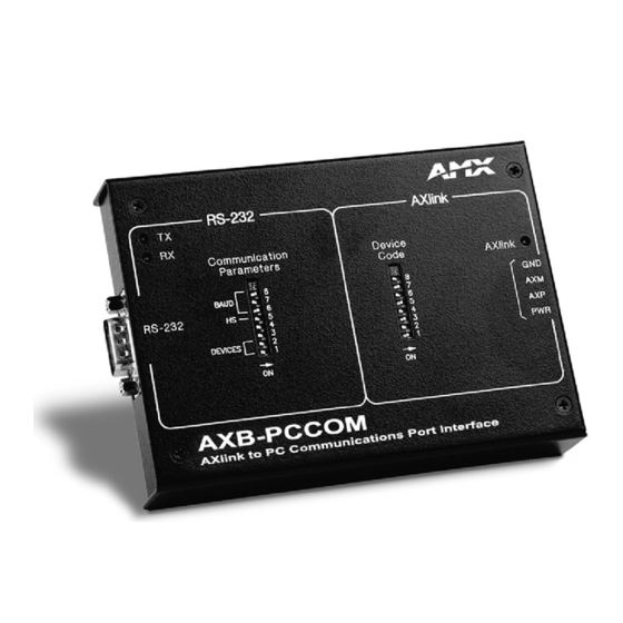
Product Information Product Information The AXB-PCCOM (FIG. 1) allows you to use a personal computer (PC) as a touch panel to control Axcess systems. TX LED AXlink RX LED COMMUNICATION DEVICE PARAMETERS CODE AXlink BAUD RS-232 AXlink connector RS-232 connector DEVICES Communication Device Code... -
Page 6: Specifications
Weight 8.60 oz. (243.80 g) Panel Components RS-232 connector A DB-9 RS-232 connector used for communication with the PC for AMX programming tools, such as Axcess and IRLIB. TX LED (Red) Blinks to indicate that the AXB-PCCOM is transmitting data. -
Page 7: Device Code
Product Information 1 2 3 4 5 6 7 8 FIG. 2 Communications Parameters DIP switch setting example The following table describes the Communications Parameters DIP switch settings and its corresponding DIP switch arrangements. Communications Parameters DIP switch settings Switch 1 Switch 2 Switch 3 and 4 Switch 5... -
Page 8: Connectors
Product Information AMX standard device numbers are assigned as follows: Cards are 1 through 25. Boxes are 96 through 127. Panels are 128 through 255. The AXB-PCCOM emulates as a touch panel. Set the device number to one in the panel range. -
Page 9: Using The Rs-232 (Db-9) Connector Control Or Data
Product Information Using the RS-232 (DB-9) connector control or data The AXB-PCCOM uses the dual-function (DB-9) RS-232 connector (FIG. 6) to communicate with the PC. RS-232 connector FIG. 6 RS-232 (DB-9) connector location on AXB-PCCOM The following table lists (DB-9) RS-232 connector pinouts and signal definitions. (DB-9) RS-232 Connector Pinouts Signal Function DB-9 (male) - Page 10 Product Information AXB-PCCOM Communications Port Interface...
-
Page 11: Programming
Programming Programming Requests Enter the numeric value only; do not enter the brackets. Examples shown are in the Axcess programming language syntax. All values expressed in brackets are true decimal values. Replace the comma delimiter, as used in the examples, with the delimiter accepted by your PC or RS-232 device. - Page 12 Programming Requests sent to the AXB-PCCOM (Cont.) Command Packet Structure and Example Get Devices Syntax: '*' <9> <CHECKSUM> Example: "'*',9,51" Request the devices and device numbers of the AXB-PCCOM. The AXB-PCCOM responds with a DEVICE LIST string. Get Level Status Syntax: '*' <7>...
-
Page 13: Send_Commands
Programming Requests sent to the AXB-PCCOM (Cont.) Command Packet Structure and Example Set Level (Byte) Syntax: '*' <3> <DEVICE> <LEVEL NO> <LEVEL> <CHECKSUM> Example "'*',3,1,0,200,246" Set level 0 on device 1 (AXlink device 129) to 200. Set Level (Word) Syntax: '*' <13>... -
Page 14: Response Commands
Programming Response Commands The following table lists the response commands sent to the AXB-PCCOM when set as device number 128, configured for four devices : Return/Requests sent to the AXB-PCCOM Command Packet Structure and Example Bus LED Status Syntax: '&' <5> <STATUS> <CHECKSUM> Examples: "'&',5,1,44"... -
Page 15: Response Mask
Programming Return/Requests sent to the AXB-PCCOM Command Packet Structure and Example Receive String Syntax: '&' <3> <DEVICE> <# BYTES> <STRING> <CHECKSUM> Example: "'&',3,0,9,'AXB-PCCOM',172" AXCESS sent the string 'AXB-PCCOM' to device 0 (AXlink device 128). Response Mask If the AXB-PCCOM receives a change, it sends data automatically. Disable this feature if the data is not used. - Page 16 ATLANTA • BOSTON • CHICAGO • CLEVELAND • DALLAS • DENVER • INDIANAPOLIS • LOS ANGELES • MINNEAPOLIS • PHILADELPHIA • PHOENIX • PORTLAND • SPOKANE • TAMPA 3000 RESEARCH DRIVE, RICHARDSON, TX 75082 USA • 800.222.0193 • 469.624.8000 • 469-624-7153 fax • 800.932.6993 technical support • www.amx.com...