Table of Contents
Advertisement
This manual has been provided for the use of authorized YAMAHA Retailers and their service personnel.
It has been assumed that basic service procedures inherent to the industry, and more specifically YAMAHA Products, are already
known and understood by the users, and have therefore not been restated.
WARNING:
IMPORTANT:
The data provided is believed to be accurate and applicable to the unit(s) indicated on the cover. The research, engineering, and
service departments of YAMAHA are continually striving to improve YAMAHA products. Modifications are, therefore, inevitable
and specifications are subject to change without notice or obligation to retrofit. Should any discrepancy appear to exist, please
contact the distributor's Service Division.
WARNING:
IMPORTANT:
I CONTENTS
To Service Personnel .......................................... 2
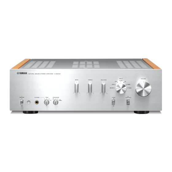
Front Panel .............................................................. 2
Rear Panels .......................................................... 3–5
Remote Control Panels ...................................... 6
Internal View ........................................................... 8
.................................................... 9
..................................... 21–27
1 0 1 0 7 7
STEREO AMPLIFIER
A-S2000
Failure to follow appropriate service and safety procedures when servicing this product may result in personal
injury, destruction of expensive components, and failure of the product to perform as specified. For these reasons,
we advise all YAMAHA product owners that any service required should be performed by an authorized
YAMAHA Retailer or the appointed service representative.
The presentation or sale of this manual to any individual or firm does not constitute authorization, certification or
recognition of any applicable technical capabilities, or establish a principle-agent relationship of any form.
Static discharges can destroy expensive components. Discharge any static electricity your body may have
accumulated by grounding yourself to the ground buss in the unit (heavy gauge black wires connect to this buss).
Turn the unit OFF during disassembly and part replacement. Recheck all work before you apply power to the unit.
.......................................... 7
............. 9–18
....................... 19–20
2008
This manual is copyrighted by YAMAHA and may not be copied or
redistributed either in print or electronically without permission.
SERVICE MANUAL
IMPORTANT NOTICE
Ic Data ................................................................. 31–34
Pin Connection Diagrams ............................ 35–36
Block Diagram ....................................................... 37
Printed Circuit Boards ................................ 38–58
Schematic Diagrams ...................................... 59–66
Replacement Parts List .............................. 67–87
Remote Control .............................................. 88–89
All rights reserved.
28–30
P.O.Box 1, Hamamatsu, Japan
'08.01
Advertisement
Table of Contents

Related Manuals for Yamaha AS2000BL


Summary of Contents for Yamaha AS2000BL
-
Page 1: Important Notice
This manual has been provided for the use of authorized YAMAHA Retailers and their service personnel. It has been assumed that basic service procedures inherent to the industry, and more specifically YAMAHA Products, are already known and understood by the users, and have therefore not been restated. -
Page 2: To Service Personnel
A-S2000 I TO SERVICE PERSONNEL AC LEAKAGE WALL EQUIPMENT TESTER OR 1. Critical Components Information OUTLET UNDER TEST EQUIVALENT Components having special characteristics are marked s and must be replaced with parts having specifications equal to those originally installed. 2. Leakage Current Measurement (For 120V Models Only) When service has been completed, it is imperative to verify INSULATING that all exposed conductive surfaces are properly insulated... -
Page 3: Rear Panels
A-S2000 I REAR PANELS A-S2000 (U, C models) A-S2000 (R model) A-S2000 (T model) - Page 4 A-S2000 A-S2000 (K model) A-S2000 (A model) A-S2000 (B model)
- Page 5 A-S2000 A-S2000 (G model) A-S2000 (L model) A-S2000 (J model)
-
Page 6: Remote Control Panels
A-S2000 I REMOTE CONTROL PANELS RAS21 RAS22 (U, C, R, T, A, B, G, L models) (K, J models) -
Page 7: Specifications
A-S2000 I SPECIFICATIONS / I General / I Audio Section / Power Supply / Minimum RMS Output Power (Power Amp. Section) / U, C models ............AC 120 V, 60 Hz (20 Hz to 20 kHz, 0.02 % THD) R, L models ......AC 110/120/220/230-240 V, 50/60 Hz 8 ohms ................. -
Page 8: Internal View
A-S2000 I INTERNAL VIEW Top View 1 FRONT (14) P.C.B. (R, L models) 2 FUNCTION (3) P.C.B. 3 FRONT (13) P.C.B. 4 MAIN (2) P.C.B. 5 FUNCTION (2) P.C.B. 6 POWER TRANSFORMER 7 MAIN (3) P.C.B. 8 MAIN (1) P.C.B. 9 FRONT (12) P.C.B. -
Page 9: Service Precautions
A-S2000 I SERVICE PRECAUTIONS / Safety measures When installing the knob unit, it is necessary to position • Some internal parts in this product contain high volt- them as specified. (Refer to “When installing the knob ages and are dangerous. Be sure to take safety mea- unit”.) sures during servicing, such as wearing insulating gloves. - Page 10 A-S2000 G When installing the knob VOL unit: e. After installation, perform following checks. • Turn the knob TC unit in both directions to a. Turn the VOLUME (VR501) counterclockwise check that it does not rub against the front fully. (Fig. 2) panel.
- Page 11 A-S2000 4. Removal of Front Frame Ass’y a. Remove 4 screws (7) to remove the frame top. (Fig. 3) b. Remove 8 screws (8). (Fig. 3) c. Remove CB501, CB504, CB517, CB519, CB521 and SW1-2. (Fig. 3) d. Remove the front frame ass’y. (Fig. 3) Frame top Front frame ass'y Front frame ass'y...
- Page 12 A-S2000 When checking the P.C.B.: • Put the rubber sheet and cloth over this unit. Then place the P.C.B.s upside down on the cloth and check it. (Fig. 4) • Reconnect all cables (connectors) that have been disconnected. • In this unit, the ground of the front frame ass’y is con- nected to the chassis.
- Page 13 A-S2000 5. Removal of Amplifier Unit a. Remove 8 screws (9) and 2 screws (0). (Fig. 5) b. Remove the frame side L. (Fig. 5) c. Remove 4 screws (A). (Fig. 5) d. Remove CB71-74, CB76, CB84 and CB406. (Fig. 5) e.
- Page 14 A-S2000 G When installing the power unit: When installing the power unit, be very careful not to cause any damage to the cable at the bottom with the end of the screw. (Fig. 6) Bottom view Cable Front side End of the screw Rear side Fig.
- Page 15 A-S2000 When checking the P.C.B.: • Remove frame panels L/R. • Put the rubber sheet and cloth over this unit. Then place the P.C.B. slantingly on the cloth and check it. (Fig. 7) • Reconnect all cables (connectors) that have been disconnected.
- Page 16 A-S2000 7. Removal of FUNCITON (2) P.C.B. a. Remove 4 screws (F) and a screw (G). (Fig. 8) b. Remove CB401-404. (Fig. 8) c. Remove the connector TR. (Fig. 8) d. Disconnect the cable (W4004) from the bottom. (Fig. 9) e.
- Page 17 A-S2000 Bottom view W4004 Fig. 9 8. Removal of BALANCE P.C.B. a. Remove 3 screws (H) and 4 screws (I). (Fig. 8) b. Remove CB59 and CB201-203. (Fig. 8) c. Remove BALANCE P.C.B.. (Fig. 8) 9. Removal of Speaker Terminal L/R a.
- Page 18 A-S2000 10. Removal of FUNCTION (1) P.C.B. and FRONT (10) P.C.B. a. Remove 9 screws (S), a screw (T), and 2 screws (U). (Fig. 10) b. Remove CB305. (Fig. 10) c. Remove the cable (W3004) from the bottom. (Fig. 11) d.
- Page 19 A-S2000 I AMP ADJUSTMENT / G Idling Adjustment Precaution for handling measuring instrument The ground side of the measuring instrument to be con- nected to the speaker terminal of this unit must be kept in DC +4.0 to +8.0 mV floating condition because this unit is equipped with the MAIN (2) P.C.B.
- Page 20 A-S2000 G Headphone DC Offset Adjustment Condition MAIN (1) P.C.B. L ch MAIN (2) P.C.B. R ch • Start adjustment 5 sec or more after the power is turned on. • No input signal. • Non loaded condition VR202 VR102 DC offset adjustment Adjust VR202 (Lch)/VR102 (Rch) so that the DC volt- age of the CB504 becomes -2.0 to +2.0mV.
-
Page 21: Updating Firmware
A-S2000 I UPDATING FIRMWARE / When replacing the following parts, be sure to write the latest firmware. FRONT P.C.B. Microprocessor (IC502) of FRONT P.C.B. G Required tools • Windows 98/2000/Me/XP, PC with a serial port (RS232C) • Firmware downloader program FlashSta.exe (Ver. -
Page 22: Operation Procedures
A-S2000 G Operation Procedures 1. Turn off the power of this unit and disconnect the power cable from the AC outlet. 2. Remove the panel side L/R and top cover. (Refer to [DISASSEMBLY PROCEDURS]) 3. Set the switch (SW301) of RS232C conversion adapter to the “FLASH UCOM”... - Page 23 A-S2000 5. Reconnect the power cable of this unit to the AC outlet. At this time, set the “POWER ON/OFF” switch to the OFF position. 6. Start up “FlashSta.exe”. “Select Program” is displayed. (Fig. 2) 7. Select Program: “Inter flash memory”, RS232C Port: “COMx (serial port of the PC connected to this unit)”.
- Page 24 A-S2000 13. “ID Check” is displayed. (Fig. 4) Click [Refer...], and select “A-S2000.s2”. (Fig. 4) The ID code and MCU type are loaded when the file is selected. (Fig. 4) Click [OK]. (Fig. 4) When [Refer...] is clicked, the open file screen is displayed. Select the firmware “A-S2000.s2”.
- Page 25 A-S2000 14. “M16C Flash Start” is displayed. (Fig. 5) Click [E.P.R...], and “Erase OK?” is displayed. (Fig. 5) Click [OK] and start writing. (Fig. 5) 15. When writing is completed, “Program OK.” is dis- played. (Fig. 5) Click [OK]. (Fig. 5) 16.
- Page 26 A-S2000 G Confirmation of Firmware Version Confirm that the firmware is updated successfully by checking the “Indication of Firmware Version” by the self-diagnostic function. For more information, refer to “SELF-DIAGNOSTIC FUNCTION”. G Indication of Firmware Version • Operation procedures Turn the “BALANCE” and “TREBLE” knobs coun- terclockwise fully and then while pressing down the “AUDIO MUTE”...
-
Page 27: Factory Reset
A-S2000 G Factory Reset Set back to the factory setting (INPUT: CD BAL). 1. Turn the "BALANCE" knob clockwise fully and then while pressing down the "AUDIO MUTE" switch, set the "POWER ON/OFF" switch to the ON position. (Fig. 7) 2. - Page 28 A-S2000 I SELF-DIAGNOSTIC FUNCTION / G Protection Information Display When the power to this unit is turned on and the power indicator is flashing, the normal operation is not avail- able because the protection function is at work. In that case, the protection information can be dis- played by following procedures.
- Page 29 A-S2000 G Details of Protection Information • PS (Power Supply) protection • TMP protection L/Rch Cause : The voltage in the power supply Cause : Abnormal temperature of heat section is abnormal. sink Normal value : 0.804 to 1.604V Normal value : 0.200 to 1.550V Detection port : PRV (FRONT P.C.B.
- Page 30 A-S2000 G Version Information G Factory Reset Set back to the factory setting (INPUT: CD BAL). • Operation procedures • Operation procedures Turn the "BALANCE" knob clockwise fully and Turn the “BALANCE” and “TREBLE” knobs coun- then while pressing down the "AUDIO MUTE" terclockwise fully and then while pressing down switch, set the "POWER ON/OFF"...
- Page 31 A-S2000 I IC DATA IC502: M38039xxxxx (FRONT P.C.B.) Single chip 8-bit microprocessor Main Main clock clock Sub-clock Sub-clock input output input output Reset input RESET COUT Data bus MICROPROCESSOR Clock generating circuit Timer 1 (8) Prescaler 12 (8) Timer 2 (8) Prescaler X (8) Timer X (8) CNTR...
- Page 32 A-S2000 Function Port Name Name Detail of Function (P.C.B.) P6-2/AN2 THM_L P6-1/AN1 PRD_R P6-0/AN0 PRD_L P5-7/INT3 RY_SPA P5-6/PWM RY_SPB P5-5/CNTR1 /ICEX P5-4/CNTR0 /CSEX P5-3/SRDY2 EV1_CE P5-2/SCLK2 EV1_CL P5-1/SOUT2 EV1_DA P5-0/SIN2 EX_DI P4-7/SRDY1/CNTR2 232_RTS SRDY1 P4-6/SCLK1 232_CTS SCLK1 P4-5/TXD1 232_TXD P4-4/RXD1 232_RXD P4-3/INT2 RY_PWR...
- Page 33 A-S2000 Function Port Name Name Detail of Function (P.C.B.) P0-3/AN11 MODEL P0-2/AN10 EXAD P0-1P/AN9 PSVA2 P0-0/AN8 PSVA1 P3-7/SRDY3 EV2_CE P3-6/SCLK3 EV2_CL P3-5/TXD3 EV2_DA P3-4/RXD3 EV_MT P3-3 (open drain) RY_DIR P3-2 (open drain) RY_BYP P3-1/DA2 RY_MMMC P3-0/DA1 RY_PHONO VREF VREF AVSS AVSS P6-7/AN7 PRV1...
- Page 34 A-S2000 IC504: LC709004A (FRONT P.C.B.) Serial parameter extension Function Port Name Name Detail of Function (P.C.B.) LED_CD FUNCTION LED CD LED_TU FUNCTION LED TUNER LED_L1 FUNCTION LED LINE1 LED_L2 FUNCTION LED LINE2 LED_BAL FUNCTION LED BALANCE LED_PHO FUNCTION LED PHONO LED_MDIR FUNCTION LED MAIN_DIRECT LED_MT...
-
Page 35: Pin Connection Diagrams
A-S2000 I PIN CONNECTION DIAGRAMS • LB1641 LC709004A-TLM-E LM61CIZ M38039xxxxx NJM2068MD-TE2 NJM7812FA NJM7912FA OP275GSR 1: COMMON 3: IN 2: INPUT 1: OUT 3: OUTPUT 2: COM TC94A81UG RH5RE58AA-T1-FA TC74HC4051AFEL 1: Vin 2: GND 3: Vout • Diodes D6SBN20 1N4002S 1SS355 D15XB20-7001 1SS244 1SS380... - Page 36 A-S2000 • Transistors 2SA970 2SA1036K 2SA1037K 2SA1708 2SA1145 2SC2240 2SC4488 2SC2705 2SD1938F 2SC2878 2SA1312-GR,BL 2SA2168 2SA2180 ST 2SC1740S 2SC1846 S 2SC2412K 2SC5291 2SC6081 ST 2SC3324-GR,BL 2SC3852 2SC6011 2SK208-Y 2SK209 5HP01C-TB-E DTA144EKA KRA104S-RTK CPH6901-TL-E DTC114EKA KRC104S-RTK DTC144EKA G1 D2 S2 1: GND COMMON 2: IN 3: OUT...
- Page 37 A-S2000 I BLOCK DIAGRAM • See page 60-62 → • See page 64-66 → • See page 59 → VOLUME & TONE CONTROL FUNCTION FRONT BALANCE SCHEMATIC DIAGRAM SCHEMATIC DIAGRAM SCHEMATIC DIAGRAM FLOATING BALANCED IC410 POWER AMPLIFIER IC404 BUFFER AMP. RY_BAL ATT.1 CD BAL L/R...
- Page 38 A-S2000 I PRINTED CIRCUIT BOARDS • Semiconductor Location Ref no. Location Ref no. Location Ref no. Location Ref no. Location Ref no. Location IC201 Q2007 Q2014 Q2021 Q2028 Q2001 Q2008 Q2015 Q2022 Q2029 Q2002 Q2009 Q2016 Q2023 Q2030 Q2003 Q2010 Q2017 Q2024 Q2031...
- Page 39 A-S2000 • Semiconductor Location Ref no. Location Ref no. Location D2019 D2033 D2020 D2034 D2021 D2035 D2022 D2036 D2023 D2037 BALANCE P.C.B. (Side B) D2024 D2038 D2027 D2039 D2032...
- Page 40 A-S2000 FUNCTION (1) P.C.B. (Side A) INPUT LINE2 TUNER LINE1 MAIN IN PRE OUT T, K, B, G models FUNCTION (2) (CB401) W3006 W3002 BALANCE (CB202) W3005 W3004 BALANCE (CB201) CB305 W3001 W3003 FUNCTION (2) (CB402) • Semiconductor Location FUNCTION (2) (CB403) FRONT (10) (W1003)
- Page 41 A-S2000 FUNCTION (1) P.C.B. (Side B) • Semiconductor Location Ref no. Location Ref no. Location Ref no. Location Ref no. Location Ref no. Location D3005 D3011 D3021 D3027 D3033 D3006 D3012 D3022 D3028 D3034 D3007 D3013 D3023 D3029 D3035 D3008 D3014 D3024 D3030...
- Page 42 A-S2000 • Semiconductor Location Ref no. Location Ref no. Location Ref no. Location Ref no. Location Ref no. Location Ref no. Location Ref no. Location Ref no. Location Ref no. Location Q4047 D4037 IC405 IC413 Q4007 Q4015 Q4023 Q4031 Q4039 Q4048 D4038 IC406...
- Page 43 A-S2000 • Semiconductor Location FUNCTION (2) P.C.B. (Side B) Ref no. Location Ref no. Location Ref no. Location Ref no. Location Ref no. Location Ref no. Location D4009 D4015 D4021 D4027 D4033 D4041 D4010 D4016 D4022 D4028 D4034 D4042 D4011 D4017 D4023 D4029...
- Page 44 A-S2000 FUNCTION (3) P.C.B. (Side A) FRONT (1) (CB501) U, C, T, K, A, B, G, J models R, L models CB25 MAIN (3) (W317) CB23 R, L models POWER TRANSFORMER • Semiconductor Location Ref no. Location IC51 FRONT (14) (W8A, W8B) IC52 D306...
- Page 45 A-S2000 FUNCTION (3) P.C.B. (Side B) U, C, T, K, A, B, G, J models R, L models • Semiconductor Location Ref no. Location R, L models...
- Page 46 A-S2000 MAIN (1) P.C.B. (Side A) MAIN (2) (CB74) MAIN (2) (CB75) MAIN (3) (W314) CB55 IC102 INR+ MAIN (2) AGND (CB71) INR- CB52 FUNCTION (2) (CB405) THMR HPRRDR PRIR PRDR HPRGND CB54 MAIN (2) (CB73) CB58 RSP_P RSP_N CB60 FRONT (12) (W101A, W101B) Note) Those parts marked with “#”...
- Page 47 A-S2000 MAIN (1) P.C.B. (Side B) MAIN (4) P.C.B. (Side B) • Semiconductor Location Ref no. Location D122 D123 Q114 Q118...
- Page 48 A-S2000 MAIN (2) P.C.B. (Side A) MAIN (1) (W103) MAIN (1) (CB54) THMR MAIN (1) HPRRDR (CB55) MAIN (3) PRIR PRDR (W315) CB75 IC202 CB72 INL- AGND INL+ FUNCTION (2) THMR (CB406) THML HPPRDR HPPRDL PRIR PRIL PRDR CB74 PRDL FRONT (1) (CB521) MAIN (1)
- Page 49 A-S2000 MAIN (2) P.C.B. (Side B) MAIN (5) P.C.B. (Side B) • Semiconductor Location Ref no. Location D222 D223 Q214 Q218...
- Page 50 A-S2000 Safety measures • Some internal parts in this product contain high voltages and are dangerous. Be sure to take safety measures during servicing, such as wearing insulating gloves. • Note that positions indicated below are dangerous even after the power is turned off because an electric charge remains and a high voltage continues to exist there.
- Page 51 A-S2000 • Semiconductor Location Ref no. Location D309 D310 D329 MAIN (3) P.C.B. (Side B) D330 Q300 Q301 Q302 Q318 Q322...
- Page 52 A-S2000 LED_MT FRONT (1) P.C.B. (Side A) LED_MDIR PDET LED_PHO /RES LED_BAL FRONT (2) P.C.B. (Side A) RY_PWR LED_L2 FRONT (6) (CB509) LED_L1 LED_TU +12C LED_CD DGND DGND FUNCTION (3) -12C SPEAKERS TRIM PHONES (W1) RY_SPA RY_SPB PSAV1 FUNCTION (1) (W3004) PSAV2 FUNCTION (1)
- Page 53 A-S2000 FRONT (1) P.C.B. (Side B) FRONT (2) P.C.B. (Side B) FRONT (3) P.C.B. (Side B) • Semiconductor Location FRONT (9) P.C.B. (Side B) Ref no. Location Ref no. Location D5004 Q5013 D5011 Q5014 D5012 Q5015 D5013 Q5016 D5014 Q5019 D5015 Q5023 D5017...
- Page 54 A-S2000 FRONT (4) P.C.B. (Side A) FRONT (5) P.C.B. (Side A) FRONT (6) P.C.B. (Side A) VOLUME INPUT FRONT (3) LED_MT (W5005A) LED_MDIR LED_PHO LED_BAL I_ISEL LED_L2 FRONT (1) LED_L1 (W5006) LED_TU LED_CD DGND +12C DGND +5STBY I_VOL MVOL+ MVOL- FRONT (3) (W5003A) •...
- Page 55 A-S2000 FRONT (4) P.C.B. (Side B) FRONT (5) P.C.B. (Side B) FRONT (6) P.C.B. (Side B) FRONT (11) P.C.B. (Side B) FRONT (7) P.C.B. (Side B) FRONT (8) P.C.B. (Side B) • Semiconductor Location Ref no. Location D345 D346 D5026 Q305 Q306...
- Page 56 A-S2000 • Semiconductor Location Ref no. Location Ref no. Location Ref no. Location Ref no. Location Ref no. Location Ref no. Location FRONT (10) P.C.B. (Side A) D1003 D1009 Q1014 Q1024 Q1032 Q1038 D1004 Q1009 Q1015 Q1025 Q1033 Q1039 D1005 Q1010 Q1016 Q1026...
- Page 57 A-S2000 • Semiconductor Location FRONT (10) P.C.B. (Side B) Ref no. Location Ref no. Location Ref no. Location Ref no. Location Q1020 D1001 D1013 Q1005 Q1021 D1002 Q1001 Q1006 Q1022 D1010 Q1002 Q1007 D1011 Q1003 Q1008 Q1029 Q1030 D1012 Q1004 Q1019 K, B, G models...
- Page 58 A-S2000 FRONT (12) P.C.B. FRONT (13) P.C.B. FRONT (14) P.C.B. (Side A) (Side A) (Side A) R, L models BALANCE MAIN (2) (CB59) VOLTAGE MAIN (1) BROWN BLACK (CB84) LSP_P LSP_N SELECTOR (CB64) 230-240V 1-2, 5-6 CB79 220V 2-3, 6-7 CB59 BLACK RSP_N...
-
Page 59: Schematic Diagrams
A-S2000 SCHEMATIC DIAGRAMS BALANCE W2001 25.2 25.7 24.6 24.6 25.7 Page 66 to FRONT (12)_CB59 CB203 -0.2 -0.8 -0.8 -25.1 -25.4 Page 62 -24.5 to FUNCTION (3)_W3 CD BAL L CD BAL L 25.2 25.7 24.6 24.6 25.7 12.6 -0.3 -0.8 -0.8 -25.1... - Page 60 A-S2000 FUNCTION 1/3 W3006 CD BAL L Page 59 to BALANCE_CB202 W3005 25.1 -11.9 24.6 24.6 -11.9 25.7 24.6 25.7 25.7 CD L Page 59 to BALANCE_CB201 W3003 Page 65 24.6 25.6 to FRONT (10)_W1002 CB301 -0.9 IN L -0.9 -0.6 -25.6 -0.6...
- Page 61 A-S2000 FUNCTION 2/3 12.5 IC404 -12.4 -12.4 IC404 24.9 OUT L 25.5 24.5 -12.4 24.5 25.5 CB406 -0.1 12.5 12.5 -0.2 -12.3 -0.7 -25.3 -25.8 Page 63 -24.6 12.5 to MAIN (2)_W202 -11.8 -25.3 -11.9 -25.7 -11.9 12.5 12.5 IC405 25.0 -12.4 -11.8...
- Page 62 A-S2000 FUNCTION 3/3 Page 66 to FRONT (14)_W8A, W8B (R, L models) To POWER TRANSFORMER (U, C, T, K, A, B, G, J models) 600mm 16.6 16.6 16.6 16.6 16.6 16.6 10.1 AC20.4 26.4 26.4 AC IN 26.4 W10A W10B POWER ON/OFF switch Page 64 to FRONT (1)_CB501...
- Page 63 A-S2000 MAIN to MAIN (2)_CB75 IC102 MAIN (4) W314 to MAIN (1)_CB52 -61.0 61.1 CB21 W315 Idling adjustment W103 60.8 AC89.5 to MAIN (2)_CB72 60.8 60.8 W318 60.8 60.8 58.2 58.2 to MAIN (2)_CB73 39.8 59.8 58.2 58.2 W316 22.0 60.1 21.2 Page 66...
- Page 64 A-S2000 FRONT 1/3 POINT A-1 XL501 (Pin 23 of IC502) POINT A-2 A-3 1 / Pin 1, 2 / Pin 3 of CB501 FRONT (9) Writing port CB501 +5M CB501 /RES 2 CB507 W5004 POWER ON POWER OFF POWER ON INPUT indicator TUNER LINE 1 LINE 2 CD BAL PHONO MAIN...
- Page 65 A-S2000 FRONT 2/3 W1001 Page 66 20.9 25.7 to FRONT (11)_CB27 25.1 20.9 25.7 25.1 24.6 24.2 24.7 25.2 24.6 24.2 -0.5 25.7 10.6 10.6 10.6 10.6 24.6 -20.7 -25.2 -20.7 -0.1 -0.1 -0.5 -0.5 -0.5 -0.5 -25.2 -0.5 -0.5 -10.5 -10.5 -10.5...
- Page 66 A-S2000 FRONT 3/3 FRONT (12) 31.9 31.9 29.5 29.2 29.7 29.7 29.7 29.7 29.7 29.7 29.2 29.2 29.2 29.2 29.2 29.5 21.1 25.9 27.8 27.4 17.5 21.1 CB27 CB59 12.3 Page 59 to BALANCE_W2001 11.7 12.3 Page 65 CB34 to FRONT (10)_W1001 -11.9 10.7 Page 63...
-
Page 67: Replacement Parts List
A-S2000 I REPLACEMENT PARTS LIST • ELECTRICAL COMPONENT PARTS WARNING G Components having special characteristics are marked s and must be replaced with parts having specifications equal to those originally installed. G The chip resistor is not supplied as a replacement part. When a chip resistor is necessary, use the following part. - Page 68 A-S2000 P.C.B. BALANCE ✻ New Parts...
- Page 69 A-S2000 P.C.B. FUNCTION ✻ New Parts...
- Page 70 A-S2000 P.C.B. FUNCTION ✻ New Parts...
- Page 71 A-S2000 P.C.B. FUNCTION ✻ New Parts...
- Page 72 A-S2000 P.C.B. FUNCTION ✻ New Parts...
- Page 73 A-S2000 P.C.B. FUNCTION and P.C.B. MAIN ✻ New Parts...
- Page 74 A-S2000 P.C.B. MAIN ✻ New Parts...
- Page 75 A-S2000 P.C.B. MAIN ✻ New Parts Note) Those parts marked with “#” are not included in the P.C.B. ass’y. /...
- Page 76 A-S2000 P.C.B. MAIN ✻ New Parts Note) Those parts marked with “#” are not included in the P.C.B. ass’y. /...
- Page 77 A-S2000 P.C.B. MAIN ✻ New Parts...
- Page 78 A-S2000 P.C.B. FRONT ✻ New Parts...
- Page 79 A-S2000 P.C.B. FRONT ✻ New Parts...
- Page 80 A-S2000 P.C.B. FRONT ✻ New Parts...
- Page 81 A-S2000 P.C.B. FRONT ✻ New Parts...
- Page 82 A-S2000 P.C.B. FRONT ✻ New Parts...
- Page 83 A-S2000 Carbon Resistors Value 1/4W Type Part No. 1/6W Type Part No. Value 1/4W Type Part No. 1/6W Type Part No. 1.0 Ω 3100 3100 10 kΩ 7100 7100 HJ35 HF85 HF45 HF45 1.8 Ω ❊ 3180 11 kΩ 7110 7110 HJ35 HF45...
- Page 84 A-S2000 • OVERALL ASS’Y 4-22 4-23 4-12 200-1 4-13 4-13 4-23 4-25 15 (2) 4-25 REAR UNIT 15 (3) 4-21 AMP L UNIT 10-3 4-21 10-16 (11) 10-3-6 10-19 10-18 AMP R UNIT 10-3-7 10-16 16 (8) 10-16 16 (7) 10-16 10-10 10-11...
- Page 85 A-S2000 ✻ New Parts ✻ New Parts...
- Page 86 A-S2000 • AMP L UNIT B, G models 2-19 U, C, R, T, K, A, L, J models 2-24 2-22 2-24 2-17 2-22 2-23 2-18 2-22 2-22 2-21 2-21 2-23 • AMP R UNIT 3-23 3-21 3-22 3-23 3-22 3-22 3-22 3-19 B, G models 3-21...
- Page 87 A-S2000 • REAR UNIT R,L models 8-37 8-6 (14) 8-35 8-15 8-11 8-11 8-21 8-32 8-36 K, B, G, L models 8-23 8-34 8-33 8-37 8-33 8-35 8-16 8-32 8-33 8-24 8-34 8-6 (13) 8-33 8-34 8-34 8-37 8-17 8-34 8-34 8-37 (10)
- Page 88 A-S2000 I REMOTE CONTROL RAS21 (U, C, R, T, A, B, G, L models) / RAS22 (K, J models) • SCHEMATIC DIAGRAM • PANELS RAS21 (U, C, R, T, A, B, G, L models) RAS22 (K, J models) RAS21 (U, C, R, T, A, B, G, L models) RAS22 (K, J models) SC73P1601MC-AA45 SC73P1601MC-AA46...
- Page 89 A-S2000 • KEY LAYOUT • KEY CODE RAS21 (U, C, R, T, A, B, G, L models) RAS22 (K, J models) Customer Data Customer Data Function Function code code code code – – – – – – 12ED A/B/C/D/E 7986 01FE OPEN/CLOSE –...
- Page 90 A-S2000...