Table of Contents
Advertisement
This manual has been provided for the use of authorized Yamaha Retailers and their service personnel.
It has been assumed that basic service procedures inherent to the industry, and more specifi cally Yamaha Products, are already known
and understood by the users, and have therefore not been restated.
WARNING:
IMPORTANT:
The data provided is believed to be accurate and applicable to the unit(s) indicated on the cover. The research, engineering, and service
departments of Yamaha are continually striving to improve Yamaha products. Modifi cations are, therefore, inevitable and specifi cations
are subject to change without notice or obligation to retrofi t. Should any discrepancy appear to exist, please contact the distributor's
Service Division.
WARNING:
IMPORTANT:
■ CONTENTS
TO SERVICE PERSONNEL ............................................2
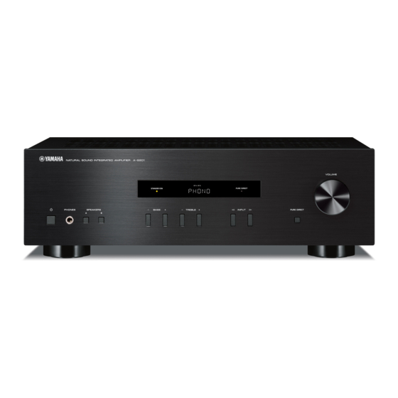
FRONT PANEL ...............................................................3
REAR PANELS ...........................................................3-5
REMOTE CONTROL PANEL ..........................................6
SPECIFICATIONS .......................................................6-7
INTERNAL VIEW ............................................................8
SERVICE PRECAUTIONS ..............................................8
DISASSEMBLY PROCEDURES ............................... 9-11
UPDATING FIRMWARE .......................................... 12-17
SELF-DIAGNOSTIC FUNCTION ............................ 18-27
1 0 1 2 9 4
INTEGRATED AMPLIFIER
A-S201
SERVICE MANUAL
IMPORTANT NOTICE
Failure to follow appropriate service and safety procedures when servicing this product may result in personal injury,
destruction of expensive components, and failure of the product to perform as specifi ed. For these reasons, we advise
all Yamaha product owners that any service required should be performed by an authorized Yamaha Retailer or the
appointed service representative.
The presentation or sale of this manual to any individual or fi rm does not constitute authorization, certifi cation or
recognition of any applicable technical capabilities, or establish a principle-agent relationship of any form.
Static discharges can destroy expensive components. Discharge any static electricity your body may have
accumulated by grounding yourself to the ground buss in the unit (heavy gauge black wires connect to this buss).
Turn the unit OFF during disassembly and part replacement. Recheck all work before you apply power to the unit.
DISPLAY DATA .............................................................28
IC DATA ...................................................................29-31
BLOCK DIAGRAM ........................................................32
WIRING DIAGRAM .......................................................33
PRINTED CIRCUIT BOARDS .................................34-39
PIN CONNECTION DIAGRAMS ...................................40
SCHEMATIC DIAGRAM ................................................41
REPLACEMENT PARTS LIST ................................43-49
REMOTE CONTROL .....................................................50
ADVANCED SETUP ......................................................51
Copyright (c) Yamaha Corporation All rights reserved.
This manual is copyrighted by Yamaha and may not be copied or
redistributed either in print or electronically without permission.
P.O.Box 1, Hamamatsu, Japan
'13.12
Advertisement
Table of Contents

Related Manuals for Yamaha A-S201


Summary of Contents for Yamaha A-S201
-
Page 1: Table Of Contents
This manual has been provided for the use of authorized Yamaha Retailers and their service personnel. It has been assumed that basic service procedures inherent to the industry, and more specifi cally Yamaha Products, are already known and understood by the users, and have therefore not been restated. -
Page 2: To Service Personnel
A-S201 ■ TO SERVICE PERSONNEL AC LEAKAGE 1. Critical Components Information WALL EQUIPMENT TESTER OR OUTLET UNDER TEST EQUIVALENT Components having special characteristics are marked ⚠ and must be replaced with parts having specifications equal to those originally installed. 2. Leakage Current Measurement (For 120V Models Only) -
Page 3: Front Panel
A-S201 ■ FRONT PANEL ■ REAR PANELS R model T model... - Page 4 A-S201 K model A model B, G models...
- Page 5 A-S201 L model...
-
Page 6: Remote Control Panel
A-S201 ■ REMOTE CONTROL PANEL ■ SPECIFICATIONS ■ Audio Section RAS2 Minimum RMS Output Power (Power Amp. Section) (40 Hz to 20 kHz, 0.2 % THD, 8 ohms / L/R drive) R, K, A, B, G models ..........100 W + 100 W T, L models ..............85 W + 85 W... - Page 7 A-S201 ■ General Power Supply • DIMENSIONS R model ........AC 110–120/220–240 V, 50/60 Hz T model ..............AC 220 V, 50 Hz Top view K model ..............AC 220 V, 60 Hz ø 60 A model ..............AC 240 V, 50 Hz B, G models ............
-
Page 8: Internal View
A-S201 ■ INTERNAL VIEW MAIN (5) P.C.B. (R model) Top view MAIN (1) P.C.B. MAIN (8) P.C.B. MAIN (7) P.C.B. POWER TRANSFORMER MAIN (6) P.C.B. MAIN (3) P.C.B. MAIN (2) P.C.B. MAIN (4) P.C.B. Front view ■ SERVICE PRECAUTIONS Safety measures •... -
Page 9: Disassembly Procedures
A-S201 ■ DISASSEMBLY PROCEDURES (Remove parts in the order as numbered.) Disconnect the power cable from the AC outlet. 1. Removal of Top Cover a. Remove screw ( ① ), 4 screws ( ② ) and 6 screws ( ③ ). (Fig. 1) b. - Page 10 A-S201 3. Removal of AMP Unit a. Remove 12 screws ( ⑦ ). (Fig. 3) b. Remove 4 screws ( ⑧ ) and screw ( ⑨ ). (Fig. 2) c. Remove CB4, CB7 and CB103. (Fig. 2) d. Remove the AMP unit. (Fig. 2) ⑧...
- Page 11 A-S201 When checking the MAIN (1) P.C.B.: • Place the P.C.B.s (with rear panel) upright. (Fig. 4) • Connect the heatsink and rear panel to the chassis with a ground lead or the like. (Fig. 4) • Reconnect all cables (connectors) that have been disconnected.
-
Page 12: Updating Firmware
A-S201 ■ UPDATING FIRMWARE When the following parts are replaced, the firmware must be updated to the latest version. MAIN P.C.B. Microprocessor: IC203 on FUNCTION (1) P.C.B. ● Confirmation of firmware version and checksum Before and after updating the firmware, check the firmware version and checksum by using the self-diagnostic function menu. - Page 13 A-S201 ● Connection Disconnect the power cable of this unit from the AC outlet. • Connect the writing port (CB201 on MAIN (1) P.C.B.) located on the rear panel of this unit to the USB port of the PC with USB to serial converter, RS-232C conversion adaptor and flexible flat cable as shown below. (Fig. 1)
- Page 14 A-S201 4. Select the type of the microprocessor and make the workspace. (Fig. 3) • Microcontroller: RL78 • Using Target Microcontroller: RL78/G13, R5F100JE • Workspace Name: Any name • Project Name: Any name • Folder: Any place Click [Browse…] and specify the place where the workspace is made. (Fig.3) 5.
- Page 15 A-S201 6. Select COMx with the Tool and click [Next]. (Fig. 4) Do not proceed to other settings until clicking [Next] is completed. (Fig. 4) Tool: COMx Fig. 4 7. Make the port (COMx) setting. (Fig. 5) a. Access the device manager. (Fig. 5) To access the device manager, click [Start], [Control panel], [System], [Hardware] and [Device manager] in this order.
- Page 16 A-S201 9. Click [Browse...] and select the firmware name. (Fig. 6) 10. Click [Start] to start writing. (Fig. 6) Writing being executed. Fig. 6...
- Page 17 A-S201 11. When writing of the firmware is completed, the screen appears as shown below. (Fig. 7) 12. Click [X] to end RFP.exe. (Fig. 7) Fig. 7 13. Disconnect the power cable of this unit from the AC outlet. 14. Remove the RS-232C conversion adaptor and flexible flat cable from the writing port (CB201 on MAIN (1) P.C.B.) of this unit.
-
Page 18: Self-Diagnostic Function
A-S201 ■ SELF-DIAGNOSTIC FUNCTION This unit has self-diagnostic functions that are intended for inspection, measurement and location of faulty point. There are 6 main menu items, each of which has sub-menu items. Listed in the table below are main menu items and sub-menu items. - Page 19 A-S201 ● Starting Self-Diagnostic Function While pressing the “BASS +” and “SPEAKERS A” keys, press the “ ” (Power) key to turn on the power, and release those 2 keys. The self-diagnostic function mode is activated. Keys of this unit “...
- Page 20 A-S201 ● Display provided when Self-Diagnostic Function started The display is as described below depending on the situation when the power to this unit is turned off. 1. When the power is turned off by usual operation: “NO PROTECT” is displayed. Then “1. VERSION/SUM” is displayed in a few seconds.
- Page 21 A-S201 2-2. When the protection function worked due to abnormal DC output. H: Displayed when the voltage is HIGHER than upper limit D C x x x L L: Displayed when the voltage is LOWER than lower limit...
- Page 22 A-S201 ● History of protection function When the protection function has worked, its history is stored in memory as backup data. Even if no abnormality is noted while servicing the unit, an abnormality which has occurred previously can be defined as long as the backup data has been stored.
- Page 23 The checksum value of the microprocessor (IC203 on MAIN (1) P.C.B.) is displayed. 1-3. MODEL/DESTINATION A 2 - G ( 0 5 4 ) The model name and destination are displayed. Not for service. Destination: R, T, K, A, G (B, G), L Model Model name A2 (A-S201)
- Page 24 A-S201 2. DISPLAY CHECK This menu is used to check operation of the FL display. Using the sub-menu, the display varies as shown below. FL display 2-1. INITIAL DISPLAY 2-2. ALL SEGMENT OFF 2-3. ALL SEGMENT ON * After check, change to next sub-menu at once.
- Page 25 A-S201 3. FACTORY PRESET This menu is used to reserve/inhibit initialization of the back-up IC. 3-1. PRESET INHIBIT (Initialization inhibited) P R S T I N H I Initialization of the back-up IC is not executed. Select this sub-menu to protect the values set by the user.
- Page 26 A-S201 4-3. TA Temperature of the heatsink (TA) is detected. The voltage at 43 pin (THM) of IC203 is displayed. Normal value: 15 to 134 (R, K, A, B, G models) 15 to 130 (T, L models) (Reference voltage: 3.3 V = 255) * If TA becomes out of the normal value range, the protection function works to turn off the power.
- Page 27 A-S201 5. PROTECTION HISTORY This menu is used to display the history of protection function. When the “SPEAKERS B” key is pressed, the protection history being displayed will be cleared. Numeric values in the figure are given as reference only.
-
Page 28: Display Data
A-S201 ■ DISPLAY DATA ● V501 : HNV-10SS61 (MAIN P.C.B.) PATTERN AREA ● PIN CONNECTION Pin No. Connection 1G 2G 3G Pin No. Connection P6 P5 Note : 1) Fn ..Filament pin 2) nG ..Grid pin 3) Pn ..Anode pin 4) NP .. -
Page 29: Ic Data
A-S201 ■ IC DATA IC203: R5F100JEAFA (MAIN (1) P.C.B.) Microprocessor * No replacement part available. TIMER ARRAY PORT 0 P00 to P03 UNIT (8ch) TI00/P00 P10 to P17 PORT 1 TO00/P01 TI01/TO01/P16 PORT 2 P20 to P27 TI02/TO02/P17 (TI02/TO02/P15) PORT 3... - Page 30 A-S201 Function Port Name Related Power Supply Detail of Function Name 1 P140/PCLBUZ0/INTP6 HPRY HP relay (HIGH = ON) 2 P120/ANI19 (Vacant) Detection of HP insertion (LOW = inserted) (HP_N_DET spare) 3 P41/TI07/TO07 (Vacant) 4 P40/TOOL0 TOOL0 For E1 debugging...
- Page 31 A-S201 Key detection for A/D port Key input (A/D) pull-up resistance 10 k-ohms 0 Ω + 1.0 kΩ + 1.0 kΩ + 1.5 kΩ + 2.2 kΩ + 3.3 kΩ + 4.7 kΩ Detected voltage value 0 – 0.22 V 0.23 –...
-
Page 32: Block Diagram
A-S201 ■ BLOCK DIAGRAM IC201 PHONO EQ. SP A PHONO NJM2068MD MUTE RY102 POWER SPEAKERS AMPLIFIER SP B RY103 PHONES MUTE RY101 (REC) LINE IC202 Relay Driver E-VOLUME BD3491FS Relay Driver POWER Power transformer IC203 Volume Microprocessor (ROTARY ENCODER) POWER SUPPLY... -
Page 33: Wiring Diagram
A-S201 ■ WIRING DIAGRAM CB501 • OVERALL ASSEMBLY MAIN (8) Top view CB204 Top view Tie AC cable and all wire Side view R model from power transformer together Tie AC cable and all wire from power transformer together MAIN (5) -
Page 34: Printed Circuit Boards
A-S201 ■ PRINTED CIRCUIT BOARDS MAIN (1) (Side A) SPEAKERS PHONO TUNER LINE POWER cable POWER TRANSFORMER Writing port T, K, A, B, G, L models CB201 CB202 Power transformer 3.3M 3.3S MPDRT_LED FL_MISO FL_STB FL_MOSI FL_SCK R model M_PLED... - Page 35 A-S201 MAIN (1) (Side B) R model K, A, B, G, L models T, K, A, B, G, L models IC202 IC203 R model • Semiconductor Location Ref no. Location Ref no. Location Ref no. Location Ref no. Location Ref no. Location Ref no.
- Page 36 A-S201 MAIN (2) (Side A) MVOL_RB MVOL_RA KEY1 KEY0 MPSW M_PLED FL_SCK POWER TRANSFORMER FL_MOSI FL_STB FL_MISO Remote control MPDRT_LED sensor 3.3S 3.3M PURE DIRECT STANDBY/ON SW_SPAB indicator MP_SW indicator 3.3M MAIN (1) (CB204) +3.3S • Semiconductor Location VOL_RA W501 chassis Ref no.
- Page 37 A-S201 MAIN (2) (Side B) IC501 • Semiconductor Location Ref no. Location D501 D502 IC501 Q502 Q503 Q504 MAIN (3) MAIN (4) (Side B) (Side B)
- Page 38 A-S201 MAIN (5) MAIN (6) (Side A) (Side A) R model VOLTAGE SELECTOR 220V – 240V 110V – 120V MAIN (1) (W102) JK101 POWER TRANSFORMER PHONES MAIN (7) MAIN (8) (Side A) (Side A) W110 • Semiconductor Location Ref no. Location...
- Page 39 A-S201 MAIN (5) MAIN (6) (Side B) (Side B) R model MAIN (7) MAIN (8) (Side B) (Side B)
-
Page 40: Pin Connection Diagrams
A-S201 ■ PIN CONNECTION DIAGRAMS • ICs BD3491FS-E2 HT16515-44LQFP LM61CIZ NJM2068MD-TE2 R5F100JEAFA R1190H033B-T1-FE • Diodes 1N4003S 1SS355VMTE-17 BAV103 D5SBA60 5A 600V DB105 UDZV2.4B UDZV4.7B UDZV5.6B Anode UDZV6.2B Anode Anode Anode – UDZV9.1B UDZV12B UDZV15B – UDZV24B Cathode Cathode Cathode Cathode... -
Page 41: Schematic Diagram
A-S201 SCHEMATIC DIAGRAM Safety measures • Some internal parts in this product contain high voltages and are dangerous. Be sure to take safety measures during servicing, such as wearing insulating gloves. MAIN • Note that the capacitors indicated below are dangerous even after the power is turned off because an electric charge remains and a high voltage continues to exist there. -
Page 42: Replacement Parts List
A-S201 ■ REPLACEMENT PARTS LIST • ELECTRICAL COMPONENT PARTS WARNING ● Components having special characteristics are marked ⚠ and must be replaced with parts having specifications equal to those originally installed. ABBREVIATIONS IN THIS LIST ARE AS FOLLOWS: C.A.EL.CHP : CHIP ALUMI.ELECTROLYTIC CAP LED.CHP... - Page 43 A-S201 MAIN Ref No. Part No. Description Markets Ref No. Part No. Description Markets ZH174800 P.C.B. MAIN * C149-150 UR779100 C.EL 1000uF ZH174900 P.C.B. MAIN C151-153 US064100 C.CE.CHP 0.01uF 50V B ZH175000 P.C.B. MAIN * C154-155 WW194100 C.MYLAR 0.1uF 100V ZH922600 P.C.B.
- Page 44 A-S201 MAIN Ref No. Part No. Description Markets Ref No. Part No. Description Markets C512-513 US035100 C.CE.CHP 0.1uF 16V B Q117-118 WF549900 TR 2SC3906K T146 R,S C514 UM397100 C.EL 10uF Q119-120 WC397600 TR 2N5401S-RTK/P C515-516 US035100 C.CE.CHP 0.1uF 16V B...
- Page 45 A-S201 MAIN Ref No. Part No. Description Markets Ref No. Part No. Description Markets YF766A00 TRANS TKABGL ⚠ TE102 ZH270100 TERM.SP 8P BANANA TE102 ZH270200 TERM.SP 8P NON-BANANA KBGL U501 WW715100 L.DTCT SIR8430MH6 V501 ZG358500 FL.DSPLY HNV-10SS61 ZG943300 FL.SPACER WP935100 HOLDER ✻...
- Page 46 A-S201 Carbon Resistors Value 1/4W Type Part No. 1/6W Type Part No. Value 1/4W Type Part No. 1/6W Type Part No. 1.0 Ω HJ35 3100 HF85 3100 11 kΩ HF45 7110 HF45 7110 ✻ 1.8 Ω 3180 12 kΩ 7120...
- Page 47 A-S201 • OVERALL ASSEMBLY R model 1 (5) 1 (7) 32 (2) 32 (3) 1 (6) 1 (8) 1 (3) 1 (2) 32 (4) 32 (1) 1 (1) 1 (4) 200-1...
- Page 48 A-S201 Ref No. Part No. Description Remarks Markets Ref No. Part No. Description Remarks Markets ZH174800 P.C.B. ASSEMBLY MAIN WE774100 BIND HEAD BONDING B-T. SCREW MFZN2B3 ZH174900 P.C.B. ASSEMBLY MAIN WE877900 BIND HEAD S-TIGHT SCREW MFZN2W3 ZH175000 P.C.B. ASSEMBLY MAIN...
-
Page 49: Remote Control
A-S201 ■ REMOTE CONTROL SCHEMATIC DIAGRAM PANEL KEY NO. LAYOUT KEY CODE RAS2 Key No. Key Name Code SLEEP 7A-30CE U1 GPM6P1001A STANDBY/ON 7E-2AD4 DIMMER 7A-82FC LINE 1 7A-C13F LINE 2 7A-18E6 PHONO 7A-14EA 7A-15EB VSS_TX TUNER 7A-16E8 TUNING 7F01-641B... -
Page 50: Advanced Setup
A-S201 ■ ADVANCED SETUP SETTING THE OPTION MENU FOR EACH INPUT SOURCE The Option menu allows you to configure various settings for each input source and recall those settings automatically when an input source is selected. Press one of the Input selector buttons to select the desired input source. - Page 51 A-S201...