Master Mgh3000, Mgh4000a, Mgh5000a, Mgh6000, Mgh7000 Owner's Operation And Installation Manual
Portable gasoline generators
Hide thumbs
Also See for Mgh3000, Mgh4000a, Mgh5000a, Mgh6000, Mgh7000:
- Owner's operation and installation manual (33 pages) ,
- Owner's operation and installation manual (37 pages) ,
- Owner's operation and installation manual (37 pages)
Table of Contents
Advertisement
R
PORTABLE GASOLINE
GENERATORS
OWNER'S OPERATION AND INSTALLATION MANUAL
Generator Models: MGH3000, MGH4000A, MGH5000A, MGH6000, and MGH7000
IMPORTANT
Read and understand this manual before operating or servicing
generator. Improper use of generator can cause serious injury.
Keep this manual for future reference.
Advertisement
Table of Contents

Related Manuals for Master Mgh3000, Mgh4000a, Mgh5000a, Mgh6000, Mgh7000


Summary of Contents for Master Mgh3000, Mgh4000a, Mgh5000a, Mgh6000, Mgh7000
- Page 1 PORTABLE GASOLINE GENERATORS OWNER’S OPERATION AND INSTALLATION MANUAL Generator Models: MGH3000, MGH4000A, MGH5000A, MGH6000, and MGH7000 IMPORTANT Read and understand this manual before operating or servicing generator. Improper use of generator can cause serious injury. Keep this manual for future reference.
-
Page 2: Table Of Contents
CONTENTS SECTION Safety Information ... 3 Product Identification ... 6 General Information ... 7 Specifications ... 7 Unpacking ... 7 Ventilation ... 8 Dust, Dirt, Rain, and Snow ... 8 High and Low Temperature Operation ... 8 Generator Features ... 9 Oil Alert System ... -
Page 3: Safety Information
SAFETY INFORMATION IMPORTANT: Read this owner’s manual and the engine owner’s manual carefully. Become familiar with this generator before trying to operate or service it. Know its uses, limitations, and any hazards involved. Improper use of generator can cause severe injury or death from explosion, fire, burns, electrical shock, or carbon monoxide poisoning. - Page 4 SAFETY INFORMATION Continued WARNING Guard against fire hazard. Keep operation area well-vented. Keep generator at least three feet away from any object. Do not place flam- mable objects near generator. • Do not use generator where flammable vapors are present. Some vapors are heavier than air.
- Page 5 SAFETY INFORMATION Continued WARNING Battery contains sulfuric acid. Battery acid is poisonous if swallowed. Contact with skin or eyes may cause severe burns. Do not tilt generator with battery installed. Tilting could cause battery acid to spill. Wear protective clothing and face shield when servicing. Keep out of children’s reach.
-
Page 6: Product Identification
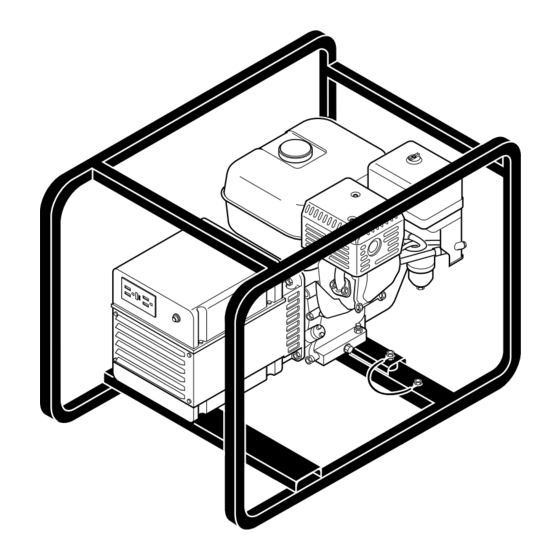
Full Power Selector Switch 120/240 Volt Circuit Receptacle Breaker Choke Lever Fuel Valve Lever Starter Grip Engine Engine ON/OFF Switch Figure 1 - Portable Generator (Model MGH4000A Shown) Provision for Auto-Idle Switch Roll Cage Gas Tank Ground Alternator Oil Dipstick... -
Page 7: General Information
GENERAL INFORMATION SPECIFICATIONS UNPACKING Master portable generators are rugged and compact. These models provide depend- able, trouble-free service. The alternators are brushless with revolving fields. Honda gasoline engines provide long life under heavy use. Honda engines have overhead valves (OHV). This provides high performance with lower fuel consumption. These engines are governed to maintain engine speed of 3600 RPM under load. -
Page 8: Ventilation
VENTILATION DUST, DIRT, RAIN, AND SNOW HIGH AND LOW TEMPERATURE OPERATION Use only in well-vented areas. Make sure area has plenty of free-moving, fresh, outside air. Never run generator in an enclosed or confined area. Never run generator inside occupied building. Engine exhaust contains poisonous carbon monoxide gas. -
Page 9: Generator Features
OIL ALERT SYSTEM GENERATOR The oil alert system protects the engine from low oil damage. This system auto- FEATURES matically shuts down the engine and prevents engine restarting if the oil level falls too low. Note: When this happens, the engine switch remains in the ON position. The oil alert system is wired into the ON/OFF Switch. -
Page 10: Ground Fault Circuit Interrupter Receptacle
GENERATOR FEATURES Continued GROUND FAULT CIRCUIT INTERRUPTER RECEPTACLE All models have a 120-volt ground fault circuit interrupter (GFCI) receptacle. The GFCI receptacle is on the control panel or top cover of alternator (model MGH3000 only). The GFCI protects you against hazardous electrical shock caused when your body becomes a path through which electricity travels to reach ground. -
Page 11: Receptacle Circuit Breaker
GENERATOR RECEPTACLE CIRCUIT BREAKER The circuit breakers protect the receptacles and alternator. Overloading generator FEATURES will trip circuit breaker. A short circuit in item being powered will also trip Continued breaker. If this occurs, unplug electrical load from receptacle. Let circuit breaker cool down. -
Page 12: Fuel
FUEL BATTERY (Model MGH7000 Only) Gasoline presents a hazard of fire or explosion. Gasoline is flammable. Its vapor is explosive. • Keep fuel out of children’s reach. • Refuel generator in a well-vented area. Do not fill fuel tank in the dark. Do not refuel while engine is running. - Page 13 BATTERY (Model MGH7000 Only) Continued If you remove battery, insulate the red, positive (+) battery cable terminal. Insulate with electrical tape. Exposed terminal may spark when generator runs. IMPORTANT: Make sure battery connections are the correct polarity. Electric start generators use negative ground, 12-volt DC starting system. Model MGH7000 has an electric starter.
- Page 14 BATTERY (Model MGH7000 Only) Continued MOUNTING BATTERY TO GENERATOR 1. Secure battery to generator by battery hold-down system. This system consists of the battery mounting bracket, hook bolts, and nut (see Figure 10). 2. Locate the red, positive (+) battery cable from starter solenoid. Connect it to the positive (+) battery terminal (see Figure 11).
-
Page 15: Generator Grounding
GENERATOR GROUNDING Grounding generator helps prevent electric shock from a ground fault condition. Locate ground lug on end of generator housing (see Figure 12). Attach a #10 stranded-copper ground wire to ground lug. Drive grounding point into ground. Grounding point can be a stake, grounding rod, or pipe. Grounding point should be copper or brass. -
Page 16: Extension Cords
EXTENSION CORDS STANDBY INSTALLATION TO HOME OR BUILDING DETERMINING ELECTRICAL LOAD FOR GENERATOR Only use grounded extension cords. Be sure to use extension cord with proper wire gauge size. See chart below. Recommended Minimum Wire Gauges (AWG) for Extension Cords Ampere AWG for Length of Cord in Feet Load... - Page 17 DETERMINING ELECTRICAL 2. Enter running watts of each item except motors. The light bulb or appliance LOAD FOR GENERATOR Continued 3. Electric motors present a special problem. They require up to three-times their 4. Add watts and starting watts of all items. This total must not be larger than the Motor Rating * –...
-
Page 18: Operation
OPERATION GENERAL INFORMATION This generator is not large enough to power your entire home. Do not connect generator to any existing electrical circuits. Plug items directly into generator receptacles. Do not exceed amperage rating of receptacles. Only use grounded cords. Use only in well-vented areas. -
Page 19: Power Cord And Plug Requirements
OPERATION POWER CORD AND PLUG REQUIREMENTS 120V, 30-amp twist-lock receptacle Continued • NEMA L5-30P plug • Three-wire, 30-amp cord 120/240V, 20 or 30-amp twist-lock receptacle • NEMA L14-20P (20-amp) or L14-30P (30-amp) plug • Four-wire, 20-amp or 30-amp cord 120 Volt 30 Amp Ground (Hot) -
Page 20: Prestart
OPERATION Continued PRESTART Operate generator on a firm, dry, and clean surface. The surface must be level. Protect generator from heavy dust, sand, dirt, rain, or snow. Do not locate genera- tor near standing water and snow. Make sure area is well-vented. Only responsible adults should use generator. - Page 21 4. Start the engine. OPERATION A. Recoil Starter Continued Turn engine switch to the ON position (see Figures 16 and 17). Remove slack from starter rope by lightly pulling starter grip. Next, pull starter rope briskly. IMPORTANT: This will prevent damage to starter. Note: If engine does not start, check the oil in the crankcase.
-
Page 22: High Altitude Operation
OPERATION Continued Choke Lever (Open Position) Figure 18 - Choke Lever Opened HIGH ALTITUDE OPERATION This generator will not perform well at high altitudes without proper adjustment. See engine owner’s manual for details. ADDING ELECTRICAL LOADS IMPORTANT: Do not overload generator. Make sure total wattage of all electri- cal loads does not exceed rated wattage of generator. -
Page 23: Stopping Engine
STOPPING ENGINE OPERATION IMPORTANT: The engine speed is preset. The throttle is locked in preset posi- Continued tion. Do not adjust throttle. Follow the steps below to stop engine. 1. Remove all electrical loads from generator (see Disconnecting Electrical Loads, page 22). Remove electrical loads one at a time. 2. -
Page 24: Maintenance And Repairs
MAINTENANCE AND REPAIRS STORAGE Only a qualified electrical service person should service and repair the alternator on this generator. Use only factory approved replacement parts. The engine speed is preset. The throttle is locked in preset position. Do not adjust throttle. Preset position lets engine run at 3600 RPM under load. -
Page 25: Troubleshooting
Note: See engine owner’s manual for engine troubleshooting. TROUBLE- SHOOTING OBSERVED PROBLEM No voltage when starting generator with no electrical load Voltage is less than normal voltage with no electrical load Voltmeter reading more than 10% high with no electrical load Voltmeter reading correct with no... -
Page 26: Wiring Diagrams
WIRING DIAGRAMS Stator 110/120V Rotor Green Green/Yellow 120/240V 20A Receptacle Circuit Breaker 20A, 25A or 30A Circuit Breaker 20A, 25A or 30A Yellow White Black Black Capacitor White White Figure 22 - Wiring Diagram, Models MGH4000A, MGH5000A, and MGH6000 Black Circuit Breaker Yellow... -
Page 27: Parts Centrals
WIRING DIAGRAMS Continued Green/Yellow 120/240V 30A Receptacle Circuit Breaker Circuit Breaker Yellow Black Black Capacitor White White Green Figure 23 - Wiring Diagram, Model MGH7000 PARTS These Parts Centrals are privately owned businesses. They have agreed to support our customer’s needs by providing original replacement parts and accessories. CENTRALS Parts Company of America 1657 Shermer Road... -
Page 28: Technical Service
Parts Under Warranty Contact authorized dealers of this product. If they cannot supply original replace- ment part(s), either contact your nearest Parts Central (see page 27) or call DESA International’s Technical Service Department at 1-800-323-5190. When calling DESA International, have ready •... -
Page 29: Illustrated Parts Lists
ILLUSTRATED PARTS LIST For Model MGH3000 Alternator Assembly PART NUMBER DESCRIPTION 099722-02 Alternator Assembly 100074-01 Top Cover 100065-01 120V, 15A Duplex (GFCI) Receptacle † 22616009 Circuit Breaker, 20 Amp † 27002002S Capacitor 26333000 Screw, M4 x 20 099863-01 Terminal Block 099701-01 Screw, M5 x 13 099848-01... -
Page 30: Parts List
ILLUSTRATED PARTS LIST For Models MGH4000A, MGH5000A, MGH6000, and MGH7000 Alternator Assembly PART NUMBER FOR MODEL MGH4000A MGH5000A 099723-01 099723-02 099844-01 099844-01 099701-01 099701-01 099760-01 099760-01 099863-01 099863-01 099863-02 099863-02 17587000 17587000 M11084-26 M11084-26 099847-01 099847-02 WLE-5 WLE-5 099843-01 099843-01 27004002S 27005003S ——... -
Page 31: Illustrated Parts List
ILLUSTRATED PARTS LIST For Model MGH3000 Roll Cage PART NUMBER 099781-01 099780-02 NEC-5C WP-5C 26020000 04110002 14138000 21834000 100406-01 This list contains replaceable parts used in your generator. When ordering parts, follow the instructions listed under REPLACEMENT PARTS on page 28 of this manual. - Page 32 ILLUSTRATED PARTS LIST For Models MGH4000A, MGH5000A, MGH6000, and MGH7000 Fuel Tank and Roll Cage...
- Page 33 This list contains replaceable parts used in your generator. When ordering parts, ILLUSTRATED follow the instructions listed under REPLACEMENT PARTS on page 28 of this PARTS LIST manual. PART NUMBER 25954000 099832-01 25978000 HC4-8C 099701-01 19508001 25985005 099743-01 099752-01 099752-02 NTC-4C NEC-5C 14138000...
-
Page 34: Illustrated Parts Lists
ILLUSTRATED PARTS LIST For Models MGH4000A, MGH5000A, MGH6000, and MGH7000 Control Panel PART NUMBER FOR MODEL MGH4000A MGH5000A 100148-01 100148-02 22616009 22616009 099833-01 099833-01 100445-01 100445-01 099956-01 099956-01 22616009 — — 22616011 — — 099834-01 099834-01 — — 26299000 26299000 099760-01 099760-01 100410-01... - Page 35 NOTES...
-
Page 36: Warranty Information
DESA International’s liability is hereby limited to the purchase price of the product and DESA International shall not be liable for any other damages whatsoever including indirect, incidental, or consequential damages.