Table of Contents
Advertisement
Quick Links
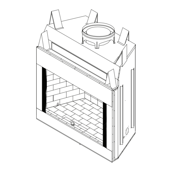
42" and 50" Wood Burning MaSonry Fireplace
oWner'S operaTion and inSTallaTion Manual
ICBO# 3507
(V)G42/50 - Smooth Face with Insulation
(V)G42R/50R - Smooth Face with Insulation and Bottom Door Rail
(V)G42H/50H - Smooth Face with Insulation and Herringbone Refractory
(V)G42HR/50HR - Smooth Face with Insulation, Bottom Door Rail
and Herringbone Refractory
SAVE THIS BOOK
This book is valuable. In addition to instructing you
on how to install and maintain your appliance, it also
contains information that will enable you to obtain re-
placement parts or accessory items when needed. Keep
it with your other important papers.
This fireplace is approved for use as a wood burning
fireplace or for use with a vented gas log approved to
ANS Z21.60, Z21.84 or RGA 2-72 standards or for use
with a vent-free gas log heater approved to ANS Z21.11.2
standard.
This wood burning fireplace complies with UL127-
CAN/ULS-S610-M87 standard as a FACTORY BUILT
APPLIANCE.
FOR CANADA: The authority having jurisdiction (such
as the municipal building department, fire department,
etc.) should be contacted before installation to deter-
mine the need to obtain a permit.
Save this manual for future reference.
For more information, visit www.desatech.com
Advertisement
Table of Contents

Related Manuals for Desa ICBO# 3507


Summary of Contents for Desa ICBO# 3507
- Page 1 42" and 50" Wood Burning MaSonry Fireplace oWner’S operaTion and inSTallaTion Manual ICBO# 3507 (V)G42/50 - Smooth Face with Insulation (V)G42R/50R - Smooth Face with Insulation and Bottom Door Rail (V)G42H/50H - Smooth Face with Insulation and Herringbone Refractory (V)G42HR/50HR - Smooth Face with Insulation, Bottom Door Rail...
-
Page 2: Table Of Contents
Unless you use DESA components, which have been designed and tested for the fireplace system, you may cause a fire hazard. • The DESA warranty will be voided by and DESA disclaims any responsibility for the following actions. a. Modification of the fireplace, components, doors, air inlet system and damper control. -
Page 3: Specifications
42" MODELS 2" CHIMNEY AIRSPACE CLEARANCE TO COMBUSTIBLE MATERIAL " AIR SPACE BACK AND SIDES OUTSIDE AIR GAS LINE KNOCKOUTS 67" 58" 49" 8" 1" 109493-01K SpeciFicaTionS ROUND TOP TERMINATION 0" TO 12" EACH SIDE BOTTOM 12" 30" 0.625" 42" 51"... - Page 4 50" MODELS 2" CHIMNEY AIRSPACE CLEARANCE TO COMBUSTIBLE MATERIAL " AIR SPACE BACK AND SIDES OUTSIDE AIR GAS LINE KNOCKOUTS 67" 58" 49" 8" 1" SpeciFicaTionS ROUND TOP TERMINATION 0" TO 12" EACH SIDE BOTTOM 12" 30" 50" 59" 32.75" 23.5"...
-
Page 5: Fireplace Installation
Fireplace inSTallaTion SELECTING LOCATION To determine the safest and most efficient location for the fireplace, you must take into consideration the following guidelines: 1. The location must allow for proper clearances (see Figures 1 and 2). 2. Consider a location where the fireplace will not be affected by drafts, air conditioning ducts, windows or doors. -
Page 6: Hearth Extension
Fireplace inSTallaTion Continued HEARTH ExTENSION A hearth extension projecting a minimum of 20" in front of and a minimum of 12" beyond each side of the fireplace opening is required to protect combustible floor construction in front of the fire- place. -
Page 7: Venting Installation
Before Installing in a Vented Crawl Space) Figure 5 - Outside Air Kit CHIMNEY PIPE The DESA chimney system consists of 12", 18", 24", 36" and 48" snap-lock, double-wall pipe segments, planned for maximum adaptability to individual site requirements. Actual lengths... - Page 8 VenTing inSTallaTion Continued USING ELBOW OFFSETS (30E-12DM) 1. To achieve desired offset, you may install combinations of 12", 18", 24", 36" and 48" length of double wall pipe (see offset chart and Figure 7). OFFSET RISE CHIMNEY LENGTH 12" 18" "...
- Page 9 VenTing inSTallaTion Continued Screws Figure 9 - Elbow Offset FIRESTOP SPACERS (FS-10) Firestop spacers are required at each point where the chimney penetrates a floor space. Their purpose is to establish and maintain the required clearance between the chimney and the combustible materials. When the pipe passes through a framed opening into a living space above, the firestop must be placed onto the ceiling from below as shown in Figure 10.
-
Page 10: Chase Installations
VenTing inSTallaTion Continued Storm Collar Flashing Cone Nail Only Outer Perimeter of Flashing Underlap Shingles at Bottom Figure 13 - Flashing Installation Installing Flashing on a Metal Roof When installing the flashing on a metal roof, it is required that putty tape be used between the flash- ing and the roof. -
Page 11: Optional Gas Line Installation
VenTing inSTallaTion Continued 10 FOOT RULE All flue gas outlet chimney terminations must extend a minimum of 3 feet in height above the highest point where it passes through the roof and must be at least 2 feet above the highest point of the roof that is within a horizontal distance of 10 feet (see Figure 17). -
Page 12: Glass Door Installation
opTional gaS line inSTallaTion Continued CAUTION: All gas piping and connections must be tested for leaks after the installation is completed. After ensuring that the gas valve is on, apply soap and water solution to all connections and joints. Bubbles forming show a leak. -
Page 13: Operation And Maintenance Guidelines
glaSS door inSTallaTion Continued INSTALLING GLASS DOORS Spring clips have been installed but some adjust- ments may be needed. If doors do not close properly or do not appear straight, see Door Adjustment. 1. With bi-fold doors completely folded, insert bottom pivot pin into pivot hole located near bottom corner of front face opening and swing door to vertical position making sure top pins... -
Page 14: Technical Service
You may have further questions about installation, operation, or troubleshooting. If so, contact DESA’s Technical Service Department at 1-866-672-6040. When calling please have your model and serial numbers of your heater ready. You can also visit DESA’s technical services web site at www.desatech.com. www.desatech.com Damper Weight... -
Page 15: Replacement Parts
replaceMenT parTS HERRINGBONE BRICK LINER Bottom Front Brick Refractory 111509-01 - VG42H Models 111509-02 - G42H Models 111515-01 - VG50H Models 111515-02 - G50H Models Bottom Rear Brick Refractory 111510-01 - VG42H Models 111510-02 - G42H Models 111512-01 - VG50H Models 111512-02 - G50H Models Right Brick Refractory 111507-01 - VG42H and VG50H Models... -
Page 16: Accessories
acceSSorieS BI-FOLD GLASS DOOR BDG42 - 42" Black Finish BDG42B - 42" Brushed Brass Finish BDG42P - 42" Platinum Finish BDG42PB - 42" Polished Brass Finish BDG50 - 50" Black Finish BDG50B - 50" Brushed Brass Finish BDG50P - 50" Platinum Finish BDG50PB - 50"...