Table of Contents
Advertisement
Quick Links
For more information, visit www.desatech.com
For more information, visit www.desatech.com
NATURAL GAS MODELS CHDV36NRA AND (V)V36NA(1) SERIES
PROPANE/LP GAS MODEL (V)V36PA(1) SERIES
WARNING: If the information in this manual is not followed
exactly, a fire or explosion may result causing property dam-
age, personal injury, or loss of life.
Do not store or use gasoline or other flammable vapors and
liquids in the vicinity of this or any other appliance.
WHAT TO DO IF YOU SMELL GAS
• Do not try to light any appliance.
• Do not touch any electrical switch
• Do not use any phone in your building.
• Immediately call your gas supplier from a neighbor's
phone. Follow the gas supplier's instructions.
• If you cannot reach your gas supplier, call the fire
department.
This appliance may be installed in an aftermarket*, permanently located, manufactured
(mobile) home, where not prohibited by state or local codes.
This appliance is only for use with the type of gas indicated on the rating plate. This appliance
is not convertible for use with other gases, unless a certified kit is used.
*Aftermarket: Completion of sale, not for purpose of resale, from the manufacturer.
FOR YOUR SAFETY
FOR YOUR SAFETY
Save this manual for future reference.
Save this manual for future reference.
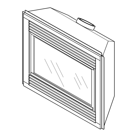
DIRECT-VENT FIREPLACE
OWNER'S OPERATION AND
INSTALLATION MANUAL
WARNING: Improper instal-
lation, adjustment, alteration,
service, or maintenance can
cause injury or property dam-
age. Refer to this manual for
correct installation and op-
erational procedures. For as-
sistance or additional infor-
mation consult a qualified
installer, service agency, or
the gas supplier.
Installation and service
must be performed by a
qualified installer, service
agency, or the gas supplier.
Advertisement
Table of Contents

Related Manuals for Desa VV36PA1 SERIES


Summary of Contents for Desa VV36PA1 SERIES
- Page 1 For more information, visit www.desatech.com For more information, visit www.desatech.com NATURAL GAS MODELS CHDV36NRA AND (V)V36NA(1) SERIES PROPANE/LP GAS MODEL (V)V36PA(1) SERIES WARNING: If the information in this manual is not followed exactly, a fire or explosion may result causing property dam- age, personal injury, or loss of life.
-
Page 2: Table Of Contents
TABLE OF CONTENTS SAFETY INFORMATION TABLE OF CONTENTS SAFETY INFORMATION ... 2 PRODUCT IDENTIFICATION ... 3 LOCAL CODES ... 3 PRODUCT FEATURES ... 4 PRE-INSTALLATION PREPARATION ... 4 LOCATION OF TERMINATION CAP ... 6 VENTING INSTALLATION INSTRUCTIONS ... 7 FIREPLACE INSTALLATION ... 17 OPERATING FIREPLACE ... -
Page 3: Product Identification
SAFETY INFORMATION Continued 5. This fireplace reaches high temperatures. Keep children and adults away from hot surfaces to avoid burns or clothing igni- tion. Fireplace will remain hot for a time after shutdown. Al- low surfaces to cool before touching. 6. -
Page 4: Product Features
PRE-INSTALLATION PREPARATION LOCATION AND SPACE REQUIREMENTS Determine the safest and most efficient location for your DESA direct-vent fireplace. Make sure that rafters and wall studs are not in the way of the venting system. Choose a location where the heat output is not affected by drafts, air conditioning ducts, windows or doors. -
Page 5: Framing And Finishing
PRE-INSTALLATION PREPARATION Continued CLEARANCES Minimum clearances to combustibles for the fireplace are as follows: Back, and sides 0"/mm Perpendicular walls 6" (152mm) Floor 0"/mm Ceiling to louver opening 42" (1067mm) Front 36" (914mm) Top of Standoffs 0"/mm Vent (See venting instructions for specific venting clearances.) Combustible material with a maximum thickness of 5/8"... -
Page 6: Location Of Termination Cap
LOCATION OF TERMINATION CAP LOCATION OF TERMINATION CAP TERMINATION CAP A = clearance above grade, veranda, porch, deck, or balcony [*12 inches (30.5mc) minimum] B = clearance to window or door that may be opened [12 inches (30.5cm) minimum] C = clearance to permanently closed window [minimum 12 inches (30.5cm) recommended to prevent condensation on window] D = vertical clearance to ventilated soffit located above the terminal within a horizontal distance of 24 inches (61cm) from the... -
Page 7: Venting Installation Instructions
INSTRUCTIONS NOTICE: Read these instructions completely be- fore attempting installation. These models are tested and approved for use with DESA (direct- vent) pipe components and terminations. The venting system must terminate on the outside of the structure and can not be attached to a chimney or flue system serving a separate solid fuel or gas burning appliance. -
Page 8: Installation Planning
VENTING INSTALLATION INSTRUCTIONS Installation Planning VENTING INSTALLATION INSTRUCTIONS Continued INSTALLATION PLANNING There are two basic types of direct-vent installation: • Horizontal Termination • Vertical Termination Horizontal Termination Installation IMPORTANT: Horizontal square terminations require only inner portion of wall firestop. Horizontal installations using round termi- nation require exterior portion of wall firestop available only in vent kit 01491 for V and VV Series or SDHTRK-58 for CHDV Series (see Figure 14, page 10). - Page 9 VENTING INSTALLATION INSTRUCTIONS Continued WARNING: Do not recess vent termination into any wall. This will cause a fire hazard. Noncombustible Exterior Wall: cap in the center of the 8 " round hole and attach to the exte- rior wall with four wood screws provided. Before attaching the vent cap to exterior wall, run a bead of non-hardening mastic (pliable sealant) around the outside edges to make a seal be- tween it and the outside wall.
- Page 10 VENTING INSTALLATION INSTRUCTIONS Installation Planning (Cont.) VENTING INSTALLATION INSTRUCTIONS Continued Combustible Exterior Wall Only: interior wall surface and attach with screws provided. See Figure 13 for horizontal termination details. 10. Place fireplace into position and shim with noncombustible ma- terial if needed. Nail or screw side flanges to framing to secure unit in place.
- Page 11 VENTING INSTALLATION INSTRUCTIONS Continued CORNER INSTALLATION Recommended Applications: • Corner ground floor installation • Ground floor installation where pipe vents horizontally through wall (over 12" horizontal pipe) • Basement installation where one foot clearance from ground to termination is possible Not to Exceed (H) Limits Square...
- Page 12 VENTING INSTALLATION INSTRUCTIONS Installation Planning (Cont.) VENTING INSTALLATION INSTRUCTIONS Continued HORIZONTAL SYSTEM INSTALLATION USING TWO 90° ELBOWS The following configurations show the minimum vertical rise requirements for a horizontal system using two 90° elbows. Venting with Two 90° Elbows Vertical (V) Horizontal (H ) Horizontal (H Horizontal (H...
-
Page 13: Installation For Vertical Termination
VENTING INSTALLATION INSTRUCTIONS Continued INSTALLATION FOR VERTICAL TERMINATION Note: Vertical restrictor must be installed in all vertical installations. 1. Determine the route your vertical venting will take. If ceiling joists, roof rafters, or other framing will obstruct the venting system, consider an offset (see Figure 19) to avoid cutting load bearing members. - Page 14 VENTING INSTALLATION INSTRUCTIONS Installation for Vertical Termination (Cont.) VENTING INSTALLATION INSTRUCTIONS Continued Vertical Termination Configurations Figures 21 through 24 show four different configurations for verti- cal termination. Venting with Two 90° Elbows Vertical (V) Horizontal (H Horizontal (H 5' min. 2' max.
-
Page 15: High Altitude Installation
VENTING INSTALLATION INSTRUCTIONS Parts Lists for Venting Kits and Components for V36 and VV36 Series HIGH ALTITUDE INSTALLATION Your DESA direct-vent fireplace has been tested and approved for elevations from 0-2000 feet (USA) and elevations from 0-4500 feet (Canada) . - Page 16 Firestop Plate SF-58 Stucco Flashing - For use with HTS-5 PARTS LISTS FOR VENTING KITS AND COMPONENTS FOR VV361 SERIES DESA (5/8") Pipe & Vent Kits Number Description 01492 Horizontal Square Termination Kit Includes: 45° Elbow (Through 5" Wall), Wall Firestop,...
-
Page 17: Fireplace Installation
FIREPLACE INSTALLATION CHECK GAS TYPE Use proper gas type for the fireplace unit you are installing. If you have conflicting gas types, do not install fireplace. See retailer where you purchased the fireplace for proper fireplace according to your gas type or to purchase gas conversion kit (see Accessories, page 39). - Page 18 FIREPLACE INSTALLATION Installing Optional Blower Accessories (Cont.) FIREPLACE INSTALLATION Continued Model BKT Installation Note: When installing the BKT thermostatically-controlled blower, you must first secure the thermal switch bracket to the blower if it has not already been factory installed. 1. Place the green ground wire with ring terminal between the bottom hole on the thermal switch bracket and the top ear hole on the blower assembly.
-
Page 19: Installing Gas Piping To Fireplace Location
FIREPLACE INSTALLATION Continued INSTALLING GAS PIPING TO FIREPLACE LOCATION WARNING: A qualified service person must con- nect fireplace to gas supply. Follow all local codes. CAUTION: For propane/LP units, never connect fireplace directly to the propane/LP supply. This heater requires an external regulator (not supplied). Install the external regulator between the fireplace and propane/LP supply. -
Page 20: Checking Gas Connections
FIREPLACE INSTALLATION Connecting Fireplace to Gas Supply Checking Gas Connections FIREPLACE INSTALLATION Continued CONNECTING FIREPLACE TO GAS SUPPLY Installation Items Needed • 5/16" hex socket wrench or nut-driver • sealant (resistant to propane/LP gas, not provided) 1. Open lower louver door panel by gently pulling forward. 2. - Page 21 Installing Optional Wireless Hand-Held Remote Control - (C)GHRCB and (C)GHRCTB Series FIREPLACE INSTALLATION Continued Equipment Shutoff Valve Meter Figure 35 - Checking Gas Joints for Natural Gas Fireplace Pressure Testing Fireplace Gas Connections 1. Open equipment shutoff valve (see Figure 33, page 20). 2.
- Page 22 FIREPLACE INSTALLATION Installing Optional Wireless Hand-Held Remote Control - (C)GHRCB and (C)GHRCTB Series Removing/Replacing Glass Door FIREPLACE INSTALLATION Continued Installing 9-Volt Alkaline Battery in Hand-Held Remote Control Unit 1. Remove battery cover on back of remote control unit. 2. Attach terminal wires to a 9-volt alkaline battery (not included). Place battery into the battery housing.
- Page 23 FIREPLACE INSTALLATION Continued 5. Close glass door frame. Lock latches by placing the bar under the tab on door and pushing down and back on latch (see Figure 42). 6. Replace screen/rod assembly by reversing step 1. 7. Replace louvers by reversing procedure under Removing Louver Panels, page 22.
- Page 24 FIREPLACE INSTALLATION Installing Logs, Lava Rock and Glowing Embers FIREPLACE INSTALLATION Continued INSTALLING LOGS, LAVA ROCK AND GLOWING EMBERS Each log is marked with a number. These numbers will help you identify the log when installing. It is very important to install these logs exactly as instructed.
-
Page 25: Operating Fireplace
OPERATING FIREPLACE FOR YOUR SAFETY READ BEFORE LIGHTING WARNING: If you do not follow these instructions exactly, a fire or explosion may result causing prop- erty damage, personal injury or loss of life. A. This appliance has a pilot which must be lighted by hand. When lighting the pilot, follow these instructions exactly. - Page 26 OPERATING FIREPLACE Optional Hand-Held Remote Operation OPERATING FIREPLACE Continued OPTIONAL HAND-HELD REMOTE OPERATION Note: All remote control accessories must be purchased sepa- rately (see Accessories, page 39). Follow instructions included with the remote control. NOTICE: You must light the pilot before using the hand-held remote control unit.
-
Page 27: Inspecting Burners
OPERATING FIREPLACE Continued Auto Shutoff Feature 1. If the average room temperature exceeds 82 degrees Fahr- enheit (28 degrees Centigrade), the hand-held remote con- trol will perform a safety override and shut the fireplace off. This feature is not available in the MANU mode. 2. -
Page 28: Cleaning And Maintenance
INSPECTING BURNERS Burner Flame Pattern CLEANING AND MAINTENANCE Glass Door Pilot and Burners Logs Venting System INSPECTING BURNERS Continued Figure 57 shows a typical flame pattern. If burner flame pattern differs from that described: • turn fireplace off (see To Turn Off Gas to Appliance, page 25) •... -
Page 29: Troubleshooting
TROUBLESHOOTING Note: For additional help, visit DESA’s technical service web site at www.desatech.com. Note: All troubleshooting items are listed in order of operation. OBSERVED PROBLEM When ignitor button is pressed, there is no spark at pilot When ignitor button is pressed, there is... - Page 30 TROUBLESHOOTING TROUBLESHOOTING Continued OBSERVED PROBLEM Burner does not light after pilot is lit Delayed ignition burner Burner backfiring during combustion Slight smoke or odor during initial operation Heater produces a whistling noise when burner is lit Glass soots Fireplace produces a clicking/ticking noise just after burners are lit or shut off Remote does not function For more information, visit www.desatech.com...
- Page 31 TROUBLESHOOTING Continued WARNING: If you smell gas • Shut off gas supply. • Do not try to light any appliance. • Do not touch any electrical switch; do not use any phone in your building. • Immediately call your gas supplier from a neighbor’s phone. Follow the gas supplier’s instructions.
-
Page 32: Illustrated Parts Breakdown And Parts List
ILLUSTRATED PARTS BREAKDOWN Models (V)V36NA(1), (V)V36NSA(1), (V)V36NHA(1), (V)V36PA(1), (V)V36PSA(1), (V)V36PHA(1) and CHDV36NRA ILLUSTRATED PARTS BREAKDOWN MODELS (V)V36NA(1), (V)V36NSA(1), (V)V36NHA(1), (V)V36PA(1), (V)V36PSA(1), (V)V36PHA(1) AND CHDV36NRA 22-5 22-6 22-2 For more information, visit www.desatech.com For more information, visit www.desatech.com 22-1 22-4 22-3 111252-01B... - Page 33 PARTS LIST This list contains replaceable parts used in your fireplace. When ordering parts, follow the instructions listed under Replacement Parts on page 36 of this manual. KEY (V)V36NA(1) (V)V36NSA(1) (V)V36NHA(1) (V)V36PA(1) (V)V36PSA(1) (V)V36PHA(1) CHDV36NRA DESCRIPTION 108010-01 108010-01 108010-02 108010-02 108011-01 108011-01 108011-02...
- Page 34 ILLUSTRATED PARTS BREAKDOWN Models (V)V36NA(1), (V)V36NSA(1), (V)V36NHA(1), (V)V36PA(1), (V)V36PSA(1), (V)V36PHA(1), CHDV36NRA ILLUSTRATED PARTS BREAKDOWN BURNER ASSEMBLY FOR MODELS (V)V36NA(1), (V)V36NSA(1), (V)V36NHA(1), (V)V36PA(1), (V)V36PSA(1), (V)V36PHA(1), CHDV36NRA For more information, visit www.desatech.com For more information, visit www.desatech.com (#56) (#56) 111252-01B...
-
Page 35: Parts List
PARTS LIST BURNER ASSEMBLY FOR MODELS (V)V36NA(1), (V)V36NSA(1), (V)V36NHA(1), (V)V36PA(1), (V)V36PSA(1), (V)V36PHA(1), CHDV36NRA This list contains replaceable parts used in your fireplace. When ordering parts, follow the instructions listed under Replacement Parts on page 36 of this manual. PART NUMBER 108759-01 11165 108763-01... -
Page 36: Replacement Parts
You may have further questions about installation, operation, or troubleshooting. If so, contact DESA’s Customer Service Depart- ment at 1-866-672-6040. When calling, please have your model and serial numbers of your heater ready. You can also visit DESA’s technical service web site at www.desatech.com. CHDV36NRA (V)V36PA(1) -
Page 37: Owner's Registration Form
Address: City: Home Phone: E-Mail: Please answer the following questions to register your product with DESA: 1. Where will the product be used? Living/Family Room Office/Warehouse If you bought this product yourself, did you plan to purchase this type of product before going into the store? 3. - Page 38 Postage Required 2701 Industrial Drive P.O. Box 90004 Bowling Green, KY 42102-9004 For more information, visit www.desatech.com For more information, visit www.desatech.com 111252-01B TAPE...
-
Page 39: Accessories
Purchase these fireplace accessories from your local retailer. If they can not supply these accessories, call DESA’s Sales Department at 1-866-672-6040. for information. You can also write to the address listed on the back page of this manual. -
Page 40: Warranty Information
DESA warrants this product to be free from defects in materials and components for two (2) years from the date of first purchase, provided that the product has been properly installed, operated and maintained in accordance with all applicable instructions. To make a claim under this warranty the Bill of Sale or cancelled check must be presented.