
Related Manuals for Honeywell PRO22IC


Summary of Contents for Honeywell PRO22IC
-
Page 1: Installation Manual
PRO-2200 Intelligent Controller Installation Manual Part Number: PRO22IC TD1146 rev0501... -
Page 3: Table Of Contents
PRO-2200 Intelligent Controller PRO22IC Installation Guide Contents Warnings and Cautions ..................4 Disclaimer ......................6 Unpacking Procedure ................... 6 Shipping Instructions .................... 7 Limited Warranty ....................7 Confidentiality ..................... 8 Description ......................9 Set Up ........................ 9 LED Operation ....................10 Power........................ -
Page 4: Warnings And Cautions
Installation Guide PRO-2200 Intelligent Controller PRO22IC Warnings and Cautions WARNING Before installation, TURN OFF the external circuit breaker which supplies power to the system. Before connecting the device to the power supply, verify that the output voltage is within specifications of the power supply. - Page 5 PRO-2200 Intelligent Controller PRO22IC Installation Guide CAUTION IF ANY DAMAGE TO THE SHIPMENT IS NOTICED, A CLAIM MUST BE FILED WITH THE COMMERCIAL CARRIER RESPONSIBLE. CAUTION Electro-static discharge can damage CMOS integrated circuits and modules. To prevent damage always follow these procedures: Use static shield packaging and containers to transport all electronic components, including completed reader assemblies.
-
Page 6: Disclaimer
Installation Guide PRO-2200 Intelligent Controller PRO22IC Disclaimer Product Liability; Mutual Indemnification In the event that a Customer receives a claim that a Product or any component thereof has caused personal injury or damage to property of others, Customer shall immediately notify Engineering Systems in writing of all such claims. -
Page 7: Shipping Instructions
PRO-2200 Intelligent Controller PRO22IC Installation Guide Shipping Instructions To ship equipment back to Engineering Systems: 1. Contact the customer service department before returning equipment at 800-323-4576. When calling please have available: • A description of the problem or reason for returning the equipment. -
Page 8: Confidentiality
Installation Guide PRO-2200 Intelligent Controller PRO22IC Confidentiality All software, drawings, diagrams, specifications, catalogs, literature, manuals and other materials furnished by Engineering Systems relating to the design, use and service of the Products shall remain confidential and shall constitute proprietary rights of Engineering Systems and Customer agrees to treat such information as confidential. -
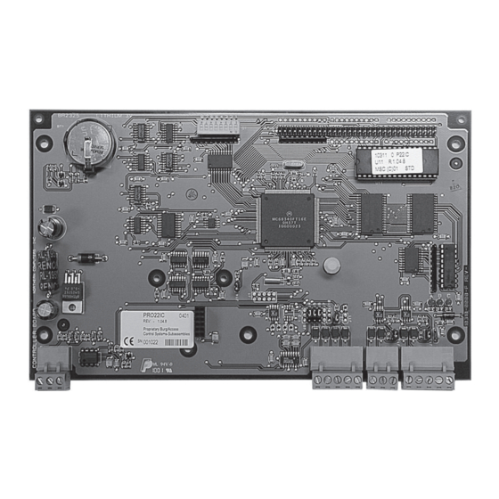
Page 9: Description
PRO-2200 Intelligent Controller PRO22IC Installation Guide Description The Intelligent Controller is the heart of the PRO-2200 and provides the real time processing for the connected I/O interfaces. It holds the database for the subsystem configuration and card holders, and the event log buffer in battery-backed memory. -
Page 10: Led Operation
Installation Guide PRO-2200 Intelligent Controller PRO22IC DIP Switch Settings: LED Operation The controller uses three on-board LEDs to provide status information during its power-up sequence and normal operation. n i t / . c n i t / . c... -
Page 11: Power
RS-232—When this port is selected as an RS-232 interface, the communication is a direct point to point connection to a host computer port (only one PRO22IC per computer port), via direct connection or modem and this device acts as Data Terminal Equipment (DTE). -
Page 12: Alarm Inputs
Installation Guide PRO-2200 Intelligent Controller PRO22IC For Wiring to an RS-485 port: TR+ is the plus side of the transmit and receive differential signal. TR– is the negative side of the transmit and receive differential signal. GND is the signal ground. The wiring for this signal is required and NOT optional. -
Page 13: Suggested Installation Sequence
PRO-2200 Intelligent Controller PRO22IC Installation Guide Suggested Installation Sequence 1. Set Jumpers and the DIP-switch per this installation guide. Install the PRO22EN and/or PRO22M4 option boards per the appropriate installation guide. Mount this board in the appropriate enclosure—If this board is being mounted in a rack the component side of the board is on right when facing the rack. -
Page 14: Wiring Diagram
Installation Guide PRO-2200 Intelligent Controller PRO22IC Wiring Diagram Tamper Switch (In Close Position Tamper CONTROLLER when Cabinet Door Switch Common BOARD Is Closed) Power Fail Battery +12VDC Power Lithium 3V Supply No Charging - C No Charging - N/C LAN Card... - Page 16 Honeywell Security & Data Collection 2700 Blankenbaker Pkwy, Suite 150 Louisville, KY 40299 (800) 675-3364 www.honeywellaccess.com...