Advertisement
Quick Links
TOWER 20 AM MCW
Outdoor Wireless Octa-QUAD™ Mirror Detector with
Anti-Mask
1. INTRODUCTION
Detector's Features
• Patented 8 independent quad PIR detectors (Octa-QUAD™)
operating in true Quad configuration with true motion recognition
(TMR) processing for each of the 8 PIR detectors and central
motion processing - can distinguish between a moving intruder
and moving trees and bushes.
•
Advanced Obsidian Black Mirror
• Smart protection against snow, rain, dust, wind and direct sunlight.
• Tamper protection prevents opening and removal from wall.
• Alarm LED is visible in sunlight.
2. SPECIFICATIONS
OPTICAL
Black Mirror Max. Coverage: At least
12 meters (40 ft) / 90º
Detector Technology: 8 independent
quad PIR detectors operating in true
Quad configuration.
Pet-Immune: Up to 18Kg (40lb.)
ELECTRICAL
Input
Power:
Two
3V
CR123A
Lithium batteries.
Caution! Risk of explosion if battery is
replaced by an incorrect type. Dispose
of used battery according to the
manufacturer's instructions.
Battery Life: 3 years (for typical use).
WIRELESS
Frequency (MHz): 315, 433.92, 868.95.
Communication Protocol:
PowerCode
MOUNTING
Mounting Type: Wall mounting
Mounting Height: 1.5 - 3.0 meters (5 – 10 ft)
Horizontal Adjustment: -45º to +45º, in 5º steps
Vertical Adjustment: 0º to -10º, in 2.5º steps
3. INSTALLATION
3.1 DIP Switches Setup
Remove the 2 detector's bottom covers (see Figure 3. steps 1-5) to gain
access to the DIP switches. Set the DIP switches according to Table 1:
Table 1 – DIP Switch Setup
DIP SW # Function
Description
OFF: Motion and masking alarm LED
Alarm
LED
is disabled (OFF).
1
OFF/ON
ON: Motion and masking alarm LED
is enabled (ON).
OFF:
24H / night
enabled (24 hours).
2
only
ON: Motion alarms are enabled only
at dark (night).
ON: AM enabled
3
AM ON /OFF
OFF: AM disabled
OFF: Masking event reported to panel
Masking
as MASKING
event
4
ON: Masking event reported to panel
reported as
as TAMPER and MASKING
Tamper
*
*
Use ON when using "old" PowerMax control panels or when
using MCR-308 if you desire masking to pass as a TAMPER
event at the control panel.
3.2 Battery Insertion
It is recommended to perform the first batteries insertion on a desk.
Upon battery insertion, the LED will flash for 60 seconds and then the
detector will enter into 15 minutes walk-test mode.
3.3 Enrolling
Enroll the detectors into the alarm system's memory as described in
the alarm system installer guide – ENROLLING section. When you
D-301620
TM
optics (patent pending).
TOP VIEW
90°
SIDE VIEW OF
EACH DETECTOR
2.4 m
(8 ft)
0
3
6
9
10
20
30
Fig. 2 - Coverage pattern
Default
ON
Motion
alarms
are
always
OFF
ON
OFF
(Figure 3)
• Day & night or night only
settings.
• Robust
housing
recessed window.
• Smart
anti
masking
distinguish between masking
spray and rain.
•
Immunity to pets weighing up
to 18 Kg (40lb), not pet alley.
•
Built in swivel bracket.
ENVIRONMENTAL
Operating Temperature: -35°C to 60°C (-31°F to 140°F)
Storage Temperature: -35°C to 60°C (-31°F to 140°F)
Humidity: 95% max.
White Light Immunity: Above 25000 lux
PHYSICAL
Dimensions (height x length x width: 157x147x124mm (6-3/16 x 5-
13/16 x 4-7/8").
Weight: 600g (21 oz)
Color: white or gray
STANDARDS COMPLIANCE
Europe 868.95, 433.92 MHz: EN 50130-4, EN 60950, EN 300220,
EN 301489, EN 50130-5. Environmental class IV. IP 55.
US Patents: 7250605, 6818881, 5693943
USA 315 MHz: CFR 47 part 15.
12 m
Canada: RSS-210
40 ft
This device complies with Part 15 of the FCC Rules and RSS-210 of
Industry and Science Canada. Operation is subject to the following two
conditions: (1) This device may not cause harmful interference, and (2)
this device must accept any interference received, including interference
that may cause undesired operation.
This device complies with the essential requirements and provisions of
Directive 1999/5/EC of the European Parliament and of the Council of 9
March 1999 on radio and telecommunications terminal equipment.
are instructed to initiate transmission from the detector. Activate the
tamper switch, i.e. open the detector bottom cover (see Fig. 3, steps
1 - 3) and then close it.
3.4 Installation
A. Bracket installation (see figure 4) – firmly fix the bracket on a
stable wall or pillar. The orientation of the fixed bracket should be
as parallel as possible to the surveyed ground surface.
B. Adjust detector's horizontal and vertical angles (see Fig. 5),
according to the surveyed ground surface. The vertical angle
indicator position for various installation height and coverage
distance combinations is detailed in Table 2 (the information refers
to a relatively flat surveyed area. however, in any case the vertical
adjustment should be verified by walk-test).
C. Fasten the detector to the bracket (see Fig. 4 step 4).
Table 2 - Vertical Adjustment Reference
Coverage Distance
Mounting
2m / 6.7ft 4m / 13ft 6m / 20ft 8m / 26ft 10m / 33 ft12m / 39 ft
Height
3.0m / 10 ft
-
1
2.5m / 8 ft
1
2.0m / 7 ft
1.5m / 5 ft
2
3.5 Test
A. Set the detector in Walk-Test mode, as follows:
Open the detector bottom cover (see Fig. 3, steps 1 - 3) and then press
and release the tamper switch. The LED will flash for 60 seconds and
then the detector will enter into 15 minutes walk-test mode.
Note: The detector automatically enters into 15 minutes walk-test
mode after battery installation or Tamper switch recovery.
B. Adjust the detector in the horizontal plane to cover the required
protected area.
Installation Instructions
with
can
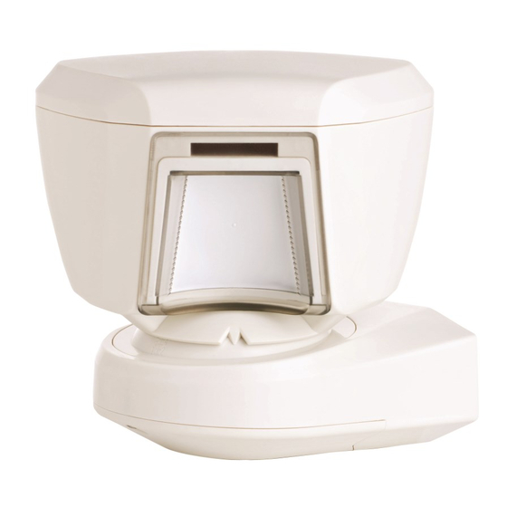
Figure 1 - TOWER 20 AM MCW
. Other patents pending.
1
2
2
3
1
2
3
4
2
3
4
5
3
4
5
-
LED
3
4
5
-
1
Advertisement

Related Manuals for Visonic TOWER 20 AM MCW


Summary of Contents for Visonic TOWER 20 AM MCW
- Page 1 TOWER 20 AM MCW Installation Instructions Outdoor Wireless Octa-QUAD™ Mirror Detector with Anti-Mask 1. INTRODUCTION • Day & night or night only Detector's Features • Patented 8 independent quad PIR detectors (Octa-QUAD™) settings. operating in true Quad configuration with true motion recognition •...
- Page 2 C. Walk into the detectors field of view. Adjust the vertical adjustment Table 3 - LED operation to receive the maximum number of detections when crossing the Event LED Operation entire 90° pattern. Verify that each time your motion is detected the First 60 sec after battery LED lights for 2 seconds and the control panel receives the alarm.
- Page 3 HORIZONTAL ADJUSTMENT ° ° (-45 to +45 Adjust Lock Release locking VERTICAL ADJUSTMENT ° ° ° to -10 in 2.5 clicks / steps) Adjust Vertical Lock angle Release locking steps COVER CLOSURE Turn cover Cover closure Push slider Figure 5 - Adjustment and Cover Closure D-301620...
- Page 4 Such modifications could void the user’s authority to operate the equipment. WARRANTY Visonic Limited (the “Manufacturer") warrants this product only (the "Product") to the original purchaser However, if the Manufacturer is held liable, whether directly or indirectly, for any loss or damage arising only (the “Purchaser”) against defective workmanship and materials under normal use of the Product for a...