GE JVB67HBB Installation Instructions Manual
Downdraft vent system
Hide thumbs
Also See for JVB67HBB:
- Features and benefits (3 pages) ,
- Owner's manual & installation instructions (40 pages)
Table of Contents
Advertisement
Installation
Instructions
If you have questions, call 800.GE.CARES or visit our Website at: www.GEAppliances.com
BEFORE YOU BEGIN
Read these instructions completely and
carefully.
IMPORTANT
•
instructions for local inspector's use.
IMPORTANT
•
governing codes and ordinances.
• Note to Installer – Be sure to leave these
instructions with the Consumer.
• Note to Consumer – Keep these
instructions for future reference.
• Note – This appliance must be properly
grounded.
• Proper installation is the responsibility of
the installer.
• Product failure due to improper installation
is not covered under the Warranty.
TOOLS YOU WILL NEED
Flat-blade screwdriver
Pliers
Jig saw
— Save these
— Observe all
Carpenter square
Duct tape
Ductwork to suit
the installation
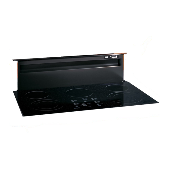
Downdraft Vent
System
REMOVE PACKAGING
Open the carton and remove parts package.
Check contents to be sure all pieces are
present. (The parts package may be attached
to the power cord.)
Remove the shipping materials. Remove the
carton and set aside. The carton can be used
as a pad when changing or adjusting vent
direction.
PARTS INCLUDED
Remote raise/lower assembly (for 36" models only)
Wire box (2)
and screws (4)
Switch cover
plate (1)
6
Stabilizing brackets
(all models) (4)
Plastic strain
Wire and white
relief (2)
connector (1)
Attachment
bracket (1)
Advertisement
Table of Contents

Related Manuals for GE JVB67HBB


Summary of Contents for GE JVB67HBB
- Page 1 Installation Downdraft Vent Instructions System If you have questions, call 800.GE.CARES or visit our Website at: www.GEAppliances.com BEFORE YOU BEGIN REMOVE PACKAGING Read these instructions completely and Open the carton and remove parts package. carefully. Check contents to be sure all pieces are present.
-
Page 2: Dimensions And Clearances
Installation Instructions DIMENSIONS AND CLEARANCES CAUTION — Wall coverings, countertops and cabinets should withstand 200°F. heat generated by any cooktop. 2″ ″ ⁄ ″ ⁄ ″ ⁄ ⁄ ″ ″ ⁄ ″ ⁄ 27″ ″ ⁄ ″ ⁄ ″ ⁄ ″... -
Page 3: Advance Planning
Installation Instructions ADVANCE PLANNING CLEARANCES DUCTWORK • Installation must conform with local codes. Prepare ductwork to vent to the outdoors. • The downdraft system with blower, motor • Use the shortest and straightest duct run and duct work will occupy the cabinet possible. -
Page 4: Installation Possibilities
Installation Instructions INSTALLATION POSSIBILITIES When the kitchen design calls for an against In an island or peninsula, the countertop can the wall installation, move 24″ deep base be extra deep to provide seating opposite of cabinet forward, 3″ to 5″ . Filler panels can the cooktop. -
Page 5: Installing The Downdraft Vent System
Installation Instructions INSTALLING THE DOWNDRAFT VENT SYSTEM 30″ COOKTOP/DOWNDRAFT UNIT JVB37 ″ ⁄ NOTE: Before you begin, measure and mark Dimension 3 to ensure that adequate flat ″ ⁄ countertop surface is available. Identify the cutout illustration for the cooktop model you are installing with this downdraft vent system. - Page 6 Installation Instructions 36″ COOKTOP/DOWNDRAFT UNIT JVB67 ″ ⁄ NOTE: Before you begin, measure and mark Dimension 3 to ensure that adequate flat ″ ⁄ countertop surface is available. Identify the cutout illustration for the cooktop model you are installing with this downdraft vent system.
-
Page 7: Power Supply
Installation Instructions INSTALLING THE DOWNDRAFT VENT SYSTEM POWER SUPPLY This downdraft vent must be supplied with 120V, 60Hz., and connected to an individual, properly grounded branch circuit, protected by a 15 or 20 ampere circuit breaker or time delay fuse. Gas Cooktops If this vent is installed in combination with a gas cooktop, it may operate from the same... - Page 8 Installation Instructions DUCTWORK LENGTH AND DUCT FITTINGS NOTE: Do not exceed 150 foot maximum permissible equivalent lengths! Flexible ducting: If flexible metal ducting is used, all equivalent feet values in the table should be doubled. The flexible metal duct should be straight and smooth and extended as much as possible. DO NOT use flexible plastic ducting.
-
Page 9: Venting Options
Installation Instructions INSTALLING THE DOWNDRAFT VENT SYSTEM VENTING OPTIONS To Change to a Left or Right Discharge Remove the 4 screws holding the blower Side-to-Side Adjustments to the mounting plate assembly. Retain The entire blower mounting plate can be screws. ″... -
Page 10: Install The Ductwork
Installation Instructions INSTALL THE DOWNDRAFT VENT INSTALL THE DUCTWORK Use minimum 26″ gauge galvanized or ″ x 10″ or 24 gauge aluminum duct 3 ⁄ 6″ round. PVC duct should be used if installing under a poured concrete slab. DO NOT USE flexible ducting. Preferred method •... - Page 11 Installation Instructions INSTALLING THE DOWNDRAFT VENT SYSTEM INSTALL THE RAISE/LOWER Remove protective film from the top of the switch trim. SWITCH Peel film from the adhesive strips on the NOTE: Step 3 is for 36″ models only. back of the switch trim. Thread the wire Skip this step if installing a 30″...
-
Page 12: Connect The Power
Installation Instructions OPTIONAL KITS CONNECT THE POWER JXRB67 optional accessory for indoor remote Plug power cord into a properly grounded location of the blower/motor assembly. Use receptacle. this kit when the blower and motor assembly will be located below the cabinet floor. INSTALL THE COOKTOP •... -
Page 13: Before You Call For Service
Before you call for service… Troubleshooting Tips Save time and money! Review the chart below first and you may not need to call for service. Problem Possible Causes What To Do Fan does not work • Press the Raise/Lower switch. The vent is not fully extended.