Table of Contents
Advertisement
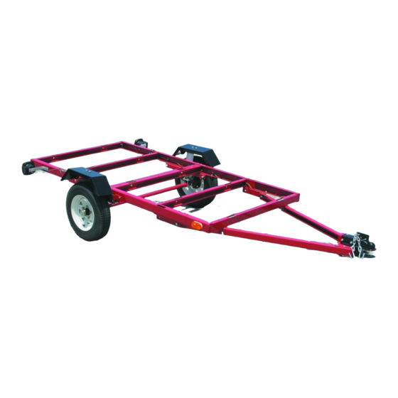
ASSEMBLY AND OPERATING INSTRUCTIONS
This trailer's Hitch Coupler MUST be properly secured to the hitch ball of the towing vehicle. After assembly and
attachment, pull up and down on the Hitch Coupler to make sure the hitch ball is fitting snugly in the Hitch Coupler.
There must be no play between the hitch ball and Hitch Coupler. If there is play, tighten the Adjustment Nut
until no play is present. If the Adjustment Nut is too tight, the Handle will not lock. Carefully read and follow the
complete instructions in this manual BEFORE setup or use.
If the Coupler is not secured properly, the ball could come loose while the trailer is in motion, possibly caus-
ing property damage, SERIOUS PERSONAL INJURY, or DEATH.
Diagrams within this manual may not be drawn proportionally.
Due to continuing improvements, actual product may differ slightly from the product described herein.
Distributed exclusively by Harbor Freight Tools
Visit our website at: http://www.harborfreight.com
Read this material before using this product.
Failure to do so can result in serious injury.
SAVE THIS MANUAL.
Copyright
©
manual or any artwork contained herein may be reproduced in any shape or form
without the express written consent of Harbor Freight Tools.
For technical questions or replacement parts, please call 1-800-444-3353.
TRAILER
MODEL 94564
IMPORTANT INFORMATION
3491 Mission Oaks Blvd., Camarillo, CA 93011
2006 by Harbor Freight Tools
4' x 8'
WARNING!
. All rights reserved. No portion of this
®
.
®
Advertisement
Table of Contents

Related Manuals for HAUL MASTER 94564


Summary of Contents for HAUL MASTER 94564
- Page 1 TRAILER 4’ x 8’ MODEL 94564 ASSEMBLY AND OPERATING INSTRUCTIONS WARNING! IMPORTANT INFORMATION This trailer’s Hitch Coupler MUST be properly secured to the hitch ball of the towing vehicle. After assembly and attachment, pull up and down on the Hitch Coupler to make sure the hitch ball is fitting snugly in the Hitch Coupler.
-
Page 2: Table Of Contents
VEHICLE LOAD LIMIT ................24 Steps for Determining Correct Load Limit ............24 INSPECTION, MAINTENANCE, AND CLEANING ........ 25 PARTS LISTS & ASSEMBLY DIAGRAM ..........26 LIMITED 90 DAY WARRANTY ............... 27 For technical questions, please call 1-800-444-3353. SKU 94564 Page 2... -
Page 3: Specifications
Keep work area clean and dry. Cluttered, damp, or wet work areas invite injuries. Keep children away from work area. Do not allow children to play in, climb on or ride in this product. REV 09b For technical questions, please call 1-800-444-3353. SKU 94564 Page 3... -
Page 4: Equipment Use And Care
It will do the job better and more safely at the capacity for which it was intended. Do not modify this product, and do not use this product for a purpose for which it was not intended. For technical questions, please call 1-800-444-3353. SKU 94564 Page 4... -
Page 5: Service
Do not attempt to power the Light Bulbs with any other type or voltage elec- trical current. Whenever possible, park the Trailer on a flat, level, paved, surface and chock both Tires to keep the Trailer from accidently moving. REV 09b For technical questions, please call 1-800-444-3353. SKU 94564 Page 5... - Page 6 This Trailer must be securely connected to the towing vehicle before loading. For technical questions, please call 1-800-444-3353. SKU 94564 Page 6...
-
Page 7: Assembly Instructions
Lay out the Front Left Side Rail (1FL), Front Right Side Rail (1FR), one Cross Mem- ber (2A), and two Cross Members (2B). Assemble these parts, using the M10 x 20 Bolts (A) and M10 Nylon Nuts (I). (See Figure A.) For technical questions, please call 1-800-444-3353. SKU 94564 Page 7... -
Page 8: Phase 2
M10 x 25 Bolts (B) and M10 Nylon Nuts (I). Then attach the T-Plate (5) under the Left and Right Connecting Rails, using the M10 x 25 Bolts (B) and M10 Nylon Nuts (I). (See Figure B.) For technical questions, please call 1-800-444-3353. SKU 94564 Page 8... -
Page 9: Phase 3
M10 x 20 Bolt M10 Nylon Nut FIGURE D Assemble the front portion and rear portion, using the M10 x 20 Bolts (A) and M10 Nylon Nuts (I). (See Figure D.) For technical questions, please call 1-800-444-3353. SKU 94564 Page 9... -
Page 10: Phase 5
Spring Plate M10 x 20 Bolt Spring M14 x 80 Bolt Nuts (I). (See Figure F.) Axle M10 Nylon Nut U-Bolt M14 Hex Nut Fender 3mm Cotter Pin Fender Seat For technical questions, please call 1-800-444-3353. SKU 94564 Page 10... -
Page 11: Phase 8
(See Figure G.) Allow all parts to dry completely. Make sure your hands are clean and the bearing packer (not included) is clean. Place fresh, clean bearing grease in the bearing packer. For technical questions, please call 1-800-444-3353. SKU 94564 Page 11... - Page 12 Wheel assemblies, using the M12 Lug Nuts (L). (See Figure G.) Note: Use a lug wrench (not included) to tighten the M12 Lug Nuts (in a “star” pattern) to 85 to 90 ft-lb. (See Figure G.) For technical questions, please call 1-800-444-3353. SKU 94564 Page 12...
- Page 13 Assemble the Tail Light Brackets (26) to the rear of the Rear Left Side Rail (1RL) and Rear Right Side Rail (1RR), using the M10 x 20 Bolts (A) and M10 Nylon Nuts (I). (See Figure H.) REV 07j For technical questions, please call 1-800-444-3353. SKU 94564 Page 13...
-
Page 14: Phase 9
WIRE CLIP GREEN BROWN YELLOW BROWN BLACK BLACK FIGURE I Locate the vehicle’s Connector Plug near the Trailer’s Coupler (7) and lay out the Trailer’s Wiring Harness wires. (See Figure I.) For technical questions, please call 1-800-444-3353. SKU 94564 Page 14... - Page 15 Strip about 3/4” of the ends of the Yellow/Brown and Green/Brown wires. (See Figure I.) Make the following connections (per color code). (See Figure I, Circle C.) Left Side Right Side Yellow-Red Wire Green-Red Wire Brown-Two Black Wires Brown-Two Black Wires For technical questions, please call 1-800-444-3353. SKU 94564 Page 15...
-
Page 16: Phase 10
Left and Right Side Rails (1FL, 1FR, 1RL, 1RR), using 3/8” diameter, rust resistant Carriage Bolts, Washers, Lock Washers, and Nuts (none included). Make sure the bolt heads do not protrude up through the plywood. (See Figure J.) For technical questions, please call 1-800-444-3353. SKU 94564 Page 16... -
Page 17: Operating Instructions
2” BALL HITCH FIGURE K HITCH Temporarily remove the 2mm R-Pin (Q) and Safety Pin (29). Then, pull up on the Trigger and lift up on the Handle. (See Figure K.) For technical questions, please call 1-800-444-3353. SKU 94564 Page 17... -
Page 18: Tire Information
- the breaking away of pieces of the carcass or tread. • Cracking means - any parting within the carcass, tread, or any components that connect the tire to the wheel center member. For technical questions, please call 1-800-444-3353. SKU 94564 Page 18... - Page 19 - that load on an individual tire that is determined by distributing to each axle its share of the curb weight, accessory weight, and normal occupant weight and dividing by 2. For technical questions, please call 1-800-444-3353. SKU 94564 Page 19...
-
Page 20: Tire Markings
71. The markings on your tire may differ.) Note: You may not find this information on all tires because it is not required by law. For technical questions, please call 1-800-444-3353. SKU 94564 Page 20... -
Page 21: Tire Inflation And Load Limit
See the Tire Care section starting on the following page for an explanation of tire pressure and see the Vehicle Load Limit section following that for an explanation of load limit. REV 09b, 09g For technical questions, please call 1-800-444-3353. SKU 94564 Page 21... -
Page 22: Tire Care
At a service station, add the missing pounds of air pressure to each tire that is underinflated. Check all the tires to make sure they have the same air pressure. For technical questions, please call 1-800-444-3353. SKU 94564 Page 22... -
Page 23: Tire Size
Tires should be removed from the rim to be inspected before being plugged and patched. A qualified mechanic should remove the tire from the rim, perform the repair, and remount the tire. For technical questions, please call 1-800-444-3353. SKU 94564 Page 23... -
Page 24: Vehicle Load Limit
If the trailer’s load exceeds the cargo and luggage load capacity, then the trailer be unsafe resulting in hazardous effects, such as: Trailer’s tires will not be able to maintain traction properly, and stopping distance will be increased significantly. For technical questions, please call 1-800-444-3353. SKU 94564 Page 24... -
Page 25: Inspection, Maintenance, And Cleaning
AND LICENSED TECHNICIANS, AND NOT BY THE BUYER. THE BUYER ASSUMES ALL RISK AND LIABILITY ARISING OUT OF HIS OR HER REPAIRS TO THE ORIGINAL PRODUCT OR REPLACEMENT PARTS THERETO, OR ARISING OUT OF HIS OR HER INSTALLATION OF REPLACEMENT PARTS THERETO. For technical questions, please call 1-800-444-3353. SKU 94564 Page 25... -
Page 26: Parts Lists & Assembly Diagram
M14 Nylon Nut M12 Nylon Nut M14 Hex Nut M12 x 20 Bolt Note: Some parts are listed and shown for illustration purposes only, and are not available individually as replacement parts. For technical questions, please call 1-800-444-3353. SKU 94564 Page 26... -
Page 27: Limited 90 Day Warranty
This warranty gives you specific legal rights and you may also have other rights which vary from state to state. 3491 Mission Oaks Blvd. • PO Box 6009 • Camarillo, CA 93011 • (800) 444-3353 REV 07j For technical questions, please call 1-800-444-3353. SKU 94564 Page 27...