
Related Manuals for EUTECH INSTRUMENTS ALPHA COND 200 - REV 3


Summary of Contents for EUTECH INSTRUMENTS ALPHA COND 200 - REV 3
- Page 1 Instruction Manual Alpha COND 200 1/8 DIN Conductivity Controller Transmitter μS / mS / ºC 68X276103 | Rev.3 | Apr 2008...
- Page 3 PREFACE This manual serves to explain the use of the Alpha COND 200 controller/transmitter. This manual functions in two ways: firstly as a step-by-step guide to help you operate the meter; secondly as a handy reference guide. This manual is written to cover as many anticipated applications of the Alpha COND 200 controller/transmitter as possible.
-
Page 4: Table Of Contents
TABLE OF CONTENTS INTRODUCTION SAFETY INFORMATION OVERVIEW RONT ANEL ANEL IRING ANEL MOUNTING THE CONTROLLER NSTALLING PLIT ERRITE LAMPING MEASUREMENT MODE PASSWORD CONDUCTIVITY CALIBRATION TEMPERATURE CALIBRATION SETUP MODE ENERAL NFORMATION ETUP MODE OVERVIEW 1 – P1.0 OINT 2 – P2.0 OINT –... -
Page 5: Introduction
1 INTRODUCTION Thank you for purchasing a Alpha COND 200 ⅛ DIN Conductivity Controller. This controller is part of a series of quality process controllers available from Eutech Instruments. These sturdy, economical conductivity controllers are designed with the features and reliability of a much more expensive instrument. Your controller includes: •... -
Page 6: Safety Information
2 SAFETY INFORMATION The Eutech Controller/Transmitter shall be installed and operated only in the manner specified in the Instruction manual. Only skilled, trained or authorized person should carry out installation, setup and operation of the instrument. Before powering up the unit, make sure that power source it is connected to, is as specified in the top label. -
Page 7: Overview
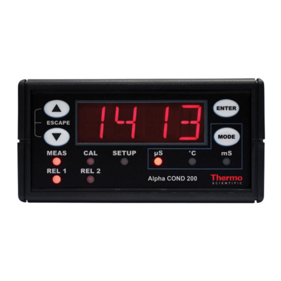
3 OVERVIEW 3.1 Front Panel The front panel consists of a 4-digit LED display, 8 LED annunciators and 4 keys. Annunciators 1. REL 1 Displayed when Relay 1 is activated 2. REL 2 Displayed when Relay 2 is activated 3. MEAS Displayed in measurement mode 4. -
Page 8: Back Panel
3.2 Back Panel The back panel consists of three different connectors that can be used with removable terminal blocks (included): Caution RELAY1 RELAY2 PT100 1. VAC live wire 2. VAC neutral wire 3. unused 4. unused 5. Relay 2 deactivated position (normally closed) 6. -
Page 9: Wiring
3.3 Wiring Caution: Ensure electrical mains are disconnected before proceeding. 1. Connect the power supply to the three-pin terminal block • VAC live wire = 1 • VAC neutral wire = 2 • VAC protective ground wire = 20 OR 21 Alpha COND 200 controller accepts voltages from 85 to 260 VAC, 50/60 Hz or DC. -
Page 10: Panel-Mounting The Controller
3.4 Panel-mounting the controller The supplied mounting hardware allows surface mounting to all panels and protective enclosures. Mounting cut-out size is 91 x 45 mm. To attach the mounting to the controller: Align the catch to the side of the controller, and insert threaded rods through catch. -
Page 11: Installing Split Ferrite Clamping
3.5 Installing Split Ferrite Clamping The power cable (L, N & E) need to be connected to the instrument with two turns through Split Ferrite (Wurth Electronika) clamp which is supplied as an accessory with the instrument. -
Page 12: Measurement Mode
MEASUREMENT MODE Press MODE to toggle between: • Conductivity measurement mode and • Temperature measurement mode Conductivity Measurement Mode The controller displays the selected Conductivity range number, R X (X ranges from 1 to 8), for 2 seconds before displaying the Conductivity measurement. Conductivity Range Range No., R Resolution... -
Page 13: Password
4 PASSWORD To access Calibration and Setup functions, you need to enter a password code. You cannot change calibration and setup parameters unless you first enter the password. The Alpha COND 200 controller features two separate passwords: • Conductivity and Temperature calibration mode password = 011 •... - Page 14 P . 000 P . 000 P .0 1 0 P .020 P . 0 11 P .022...
-
Page 15: Conductivity Calibration
5 CONDUCTIVITY CALIBRATION IMPORTANT: When Calibration mode is entered, controller automatically goes into a “HOLD” mode where the 4-20 mA output freezes and relays are de-activated (if it was in an activated condition). Upon return to measurement mode, both 4-20mA output and relay activities resume, depending on settings. - Page 16 50 9 50 0 ENTER d o n e ENTER Notes: You can view the calibrated Conductivity value from Setup program. See Setup program P5.0. Controller displays calibrated conductivity point for selected range. If calibration is not done for the selected range, controller displays ‘- - - -‘. If after thorough cleaning of electrode and ERR1 is displayed after an attempted calibration, consider changing electrode.
-
Page 17: Temperature Calibration
6 TEMPERATURE CALIBRATION IMPORTANT: When Calibration mode is entered, controller automatically goes into a “HOLD” mode where the 4-20 mA output freezes and relays are de-activated (if it was in an activated condition). Upon return to measurement mode, both 4-20mA output and relay activities resume, depending on settings. -
Page 18: Setup Mode
2 2 .5 2 5.0 ENTER d o n e 7 SETUP MODE 7.1 General Information IMPORTANT: When Setup mode is entered, controller automatically goes into a “HOLD” mode where the 4-20 mA output freezes and relays are de-activated (if it was in an activated condition). -
Page 19: Setup Mode Overview
7.2 Setup mode overview P1.0: Set Point 1 P1.1: select relay 1 set point value P1.2: select relay 1 as low or high set point P1.3: set relay 1 hysteresis value P2.0: Set Point 2 P2.1: select relay 2 set point value P2.2: select relay 2 as low or high set point P2.3: set relay 2 hysteresis value P3.0: Range... -
Page 20: Set Point 1 - P1.0
7.3 Set Point 1 – P1.0 Setup program P1.0 allows you to set parameters for relay 1. P1.1: select relay 1 set point value P1.2: select relay 1 as low or high set point P1.3: set relay 1 hysteresis value (dead band) P 1 .0 P 1 .1 P 1 .2... - Page 21 P1.3: Set Hysteresis value Hysteresis prevents rapid contact switching if measured value is fluctuating near the set point. Once activated, relay will not de-activate until measured value reaches set point plus hysteresis value. Example: Low set point is 200.0 µS/cm and hysteresis 100.0 µS/cm, relay will activate when value is below 200.0 µS/cm, but will not de-activate till measured Conductivity value rises above 300.0 µS/cm.
-
Page 22: Set Point 2 - P2.0
7.4 Set Point 2 – P2.0 Setup program P2.0 allows you to set parameters for relay 2. P2.1: select relay 2 set point value P2.2: select relay 2 as low or high set point P2.3: set relay 2 hysteresis value (dead band) P 2 .0 P 2 .1 P 2 .2... - Page 23 P2.3: Set Hysteresis value Hysteresis prevents rapid contact switching if measured value is fluctuating near the set point. Once activated, relay will not de-activate until measured value reaches set point plus hysteresis value. Example: High set point is 1800.0 µS/cm and hysteresis 100.0 µS/cm, relay will activate when value is above 1800.0 µS/cm, but will not de-activate till measured Conductivity value drops below 1700.0 µS/cm.
-
Page 24: Measurement Range Selection - P3.0
7.5 Measurement Range Selection – P3.0 Setup program P3.0 is for selecting the range of measurement. P3.1: select measurement range and corresponding cell constant P 3 . 0 P 3 . 1 R N GE 2000 K 10 . Press ▲and ▼keys together (ESCAPE) at anytime, to leave the Setup mode and return to Measurement mode. -
Page 25: Configure Temperature Settings - P4.0
7.6 Configure Temperature Settings – P4.0 Setup program P4.0 is for selecting ATC or MTC, set temperature coefficient values, and select normalization temperature P4.1: ATC or MTC mode (default : ATC mode) P4.2: set temperature coefficient (default : 2.10 %) P4.3: set Normalization temperature (default : 25.0 P 4 .1 P 4 .2... -
Page 26: Viewing Conductivity Calibration Data - P5.0
7.7 Viewing Conductivity Calibration Data – P5.0 Program 5 is a “view only” option, which displays the value at which calibration was performed. P5.1: view Calibrated conductivity value (if no calibration performed for this range, controller displays ‘- - - - ‘. These parameters will change each time you recalibrate the controller. -
Page 27: Viewing Conductivity/ Temperature Electrode Data - P6.0
7.8 Viewing Conductivity/ Temperature Electrode Data – P6.0 Program 6 has two “view only” options that let you check the electrode parameters for diagnostic purposes. P5.1: view revised cell constant value of electrode P5.2: view temperature probe offset (ATC on only) These parameters will change each time you recalibrate the controller. -
Page 28: Controller Reset - P7.0
7.9 Controller Reset – P7.0 Resets the controller to factory default values. • Conductivity range remains unchanged based on last selected range • All calibration data and conductivity calibration factor are reset • SP 1 is reset to 10 % of full scale •... -
Page 29: Relays
8 RELAYS The Alpha COND 200 features two SPDT non-powered relays; rated for 6A at 110 VAC, 250 VAC maximum. When your process exceeds the set parameters of a relay set point, the REL 1 or REL 2 indicator lights up. To set parameters for relay one and relay two, see Setup programs P1.0 and P2.0. -
Page 30: Specifications
10 SPECIFICATIONS Conductivity Range Resolution Cell Constant 0.00 – 20.00 µS/cm 0.01 µS/cm 0.0 – 200.0 µS/cm 0.1 µS/cm 0.0 – 200.0 µS/cm 0.1 µS/cm 0 – 2000 µS/cm 1 µS/cm 0.00 – 10.00 mS/cm 0.01 mS/cm 0.00 – 20.00 mS/cm 0.01 mS/cm 0.0 –... -
Page 31: Accessories
11 ACCESSORIES Product Description Code no. Conductivity cell, Epoxy body, Graphite sensor, w/3-wire ECCONSEN89X Pt100, k = 0.1 Conductivity cell, Epoxy body, Graphite sensor, w/3-wire ECCONSEN88X Pt100, k = 1.0 Note: Above Conductivity electrodes withstand up to 3 bar pressure. These cells have integral 1.0 m, 5-wire double-shielded open-ended cable. - Page 32 Appendix 1: Simple Explanation on the Function of Hysteresis S P 1 S e t t o L O S P 2 S e t t o H I R E L A Y O N The controller relay activates when the set-point is reached.
- Page 33 Appendix 3: External Relays The relays on the Alpha COND 200 series controller are rated for 6 amps at 110 VAC and can be wired directly to your final control element (provided its power requirements does not exceed this). However, to preserve the life of your controller, or if higher power is needed, it is recommended that you use the controller relay to drive an external relay.
-
Page 34: General Information
12 GENERAL INFORMATION Warranty Thermo Scientific warrants this product to be free from significant deviations in material and workmanship for a period of one year from the date of purchase. If repair is necessary and has not been the result of abuse or misuse within the warranty period, please return by freight pre-paid and amendment will be made without any charge. - Page 36 For more information on Thermo Scientific products, contact your nearest distributor or visit our website listed below: Thermo Scientific Oakton Instruments Water Analysis P.O Box 5136, Environmental Instruments Vernon Hills, IL 60061, USA Blk 55, Ayer Rajah Crescent, Tel (in U.S.): 888-462-5866 #04-16/24 Singapore 139949 Tel (outside U.S.): 1-847-549-7600 Tel: (65) 6778 6876...