
Related Manuals for EUTECH INSTRUMENTS ALPHA CON 500 2-WIRE TRANSMITTER


Summary of Contents for EUTECH INSTRUMENTS ALPHA CON 500 2-WIRE TRANSMITTER
- Page 1 Instruction Manual CON 500 LCD Transmitter Conductivity Transmitter with Display lpha CON500 MEAS 1413 READY µS °C 2-wire Conductivity Transmitter 68X216867 Rev 0 11/04 Technology Made Easy ...
- Page 4 Authorized Distributor. Eutech Instruments will not accept any responsibility for damage or malfunction to the transmitter caused by improper use of the instrument. The information presented in this manual is subject to change without notice as improvements are made, and does not represent a commitment on the part of Eutech Instruments.
-
Page 5: Table Of Contents
TABLE OF CONTENTS INTRODUCTION ................... 1 PREPARATION ..................2 (SL2 P )........... 3 OWER UPPLY EQUIREMENTS OSITION (SL1 P ) ..3 ONNECTING THE LECTRODE AND EMPERATURE ENSOR OSITION 2.2.1 To connect the Conductivity electrode: ..........3 2.2.2 To connect ATC temperature sensor: ..........4 INSTALLATION .................. - Page 6 SPECIFICATIONS ................25 ACCESSORIES................26 WARRANTY ..................27 RETURN OF ITEMS ................ 27...
-
Page 7: Introduction
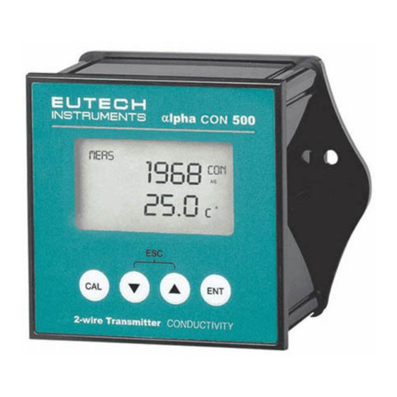
Instruction Manual CON 500 INTRODUCTION Thank you for selecting a CON 500 LCD Transmitter. This isolated output 4-20mA transmitter is a sturdy microprocessor-based instrument that measures conductivity and temperature and transmits its output via the 2-wire power supply loop. This transmitter has many user-friendly features – all of which are completely accessible through the water-resistant membrane keypad. -
Page 8: Preparation
Instruction Manual CON 500 PREPARATION Remove screws from the four corners at the back of the Transmitter, and remove back cover. Connectors should be exposed as follows: Figure 1 – Connection Guide All wiring is done on 2 detachable connectors: – 9-pin connector (located on SL1 position) for Conductivity electrode and temperature sensor;... -
Page 9: Power Supply
Instruction Manual CON 500 Power Supply Requirements (SL2 Position) The CON 500 transmitter requires a 12 to 24V DC power supply. Other Transmitters and/or a chart recorder may be connected in the loop. Insert positive loop wire from power supply to pin 1, tighten screw. Insert negative loop wire to pin 2, tighten screw. -
Page 10: To Connect Atc Temperature Sensor
Instruction Manual CON 500 2.2.2 To connect ATC temperature sensor: For Automatic Temperature Compensated (ATC) Conductivity readings, an in-built temperature sensor is usually integrated in the industrial conductivity electrodes. Otherwise, a separate 100Ω Pt RTD temperature probe can be used. 3 wire temperature sensor Insert the Pt100 input wire to pin 5 of SL1 connector. -
Page 11: Installation
Instruction Manual CON 500 INSTALLATION Mechanical Dimensions lpha CON500 2-wire Conductivity Transmitter Wall Mount - 5 -... -
Page 12: Panel Mount
Instruction Manual CON 500 Panel Mount 1. Prepare panel cut-out of 92.0 mm by 92.0 mm Panel (side) 2. Remove back cover of transmitter and slide it through panel cut-out 4. Thread rods through lugs until transmitter is held in place against panel 3. -
Page 13: Display And Keypad Functions
Instruction Manual CON 500 DISPLAY AND KEYPAD FUNCTIONS Display The LCD has a primary and secondary display. • The primary display shows the measured conductivity value. • The secondary display shows the measured temperature. In Calibration mode, measured conductivity values are displayed here. Primary Display (Upper Display) SETUP... -
Page 14: Keypad
Instruction Manual CON 500 Keypad lpha CON500 MEAS 1413 READY µS °C 2-wire Conductivity Transmitter The four-button keypad allows easy and quick operations of the Transmitter. Function Brings you directly into the Calibration mode. If you were in Conductivity Measurement mode, press CAL to enter Conductivity Calibration mode. -
Page 15: Calibration
Instruction Manual CON 500 CALIBRATION Important Information on Transmitter Calibration Calibration should be carried when you are using your transmitter with a new electrode for the first time or when you suspect that the transmitter/electrode is out of calibration. Your transmitter allows you to perform temperature calibration and conductivity calibration. - Page 16 Instruction Manual CON 500 Table 1 Conductivity Recommended Calibration Solution Measuring Range Range 19.99 µS 6.00 to 17.00 µS 0.00 199.9 µS 60.0 to 170.0 µS 1999 µS 600 to 1700 µS 0.00 10.00 mS 6.00 to 7.00 mS 0.00 19.99 mS 6.00 to 17.00 mS 199.9 mS...
-
Page 17: Temperature Calibration
Instruction Manual CON 500 Temperature Calibration You need to perform temperature calibration if your transmitter temperature reading is inaccurate or if the transmitter’s cell constant setting is changed. It is because the transmitter’s temperature offset calibration will be erased once a new cell constant is selected. -
Page 18: Conductivity Calibration
Instruction Manual CON 500 Conductivity Calibration MEAS A 1-point Calibration is required for this transmitter. If 1578 µS the calibration process is aborted, your transmitter will revert to the previous calibration data. °C Organize your calibration standard solution 25.5 in two beakers – one for rinsing and the other for calibration. -
Page 19: Advanced Setup Functions
Instruction Manual CON 500 ADVANCED SETUP FUNCTIONS The advanced setup mode lets you customize your transmitter’s preferences and defaults. This transmitter features different sub groups that organize all setup parameters. The sub-groups are: Range and Zooming Selection Setting Your CON 500 transmitter provides six selections of conductivity measurement ranges to suit your process application needs. - Page 20 Instruction Manual CON 500 For zooming setting, use the ▲ or ▼ keys to set SETUP the conductivity low zoom value for the 4 mA 0.00 µS HOLD current and press the ENT key to confirm. The transmitter now displays the high zoom value setup.
-
Page 21: Temperature Compensation Setting
Instruction Manual CON 500 Temperature Compensation Setting Conductivity readings are affected by temperature. Under varying temperature conditions, use ATC to compensate for the conductivity values. If temperature of sample is constant, and a temperature sensor/probe is not available, Manual Temperature Compensation can be utilized. 6.2.1 Automatic Temperature Compensation For automatic temperature compensation (ATC) selection, connect the ATC sensor... -
Page 22: Manual Temperature Compensation
Instruction Manual CON 500 6.2.2 Manual Temperature Compensation For manual temperature compensation you can set the process and calibration temperatures. This allows calibration at a temperature other than the process temperature. Example: setting a calibration temperature of 25°C lets you calibrate using standard solutions at 25°C, even if your process temperature is different from 25°C. - Page 23 Instruction Manual CON 500 SETUP HOLD SETUP SETUP HOLD HOLD SETUP SETUP HOLD HOLD °C SETUP HOLD Temperature Compensation Setting Chart – alpha CON 500 Transmitter - 17 -...
-
Page 24: Hold Current Setting
Instruction Manual CON 500 HOLD Current Setting SETUP When Transmitter is in CAL or SETUP modes, it HOLD automatically goes into a ‘HOLD’ mode. To indicate Transmitter is in ‘HOLD’ mode, output current can be set to 22 mA output by activating the ‘HLD On’. Press the ENT key and use ▲... -
Page 25: Temperature Coefficient And Normalization Temperature Setting
Instruction Manual CON 500 Temperature Coefficient and Normalization Temperature Setting Since different process liquid may require different temperature coefficient factor for its temperature compensation calculation, CON 500 transmitter allows 0 to 10% temperature coefficient factor adjustment to cater for your different application needs. -
Page 26: Cell Constant Setting
Instruction Manual CON 500 Cell Constant Setting You can select up to three types of cell constant in the setup mode: - K=1.0, K=0.1 or K=10. From the measurement mode, SETUP Press the ENT key to enter the setup mode. Use HOLD the ▲... -
Page 27: Viewing Calibration Point
Instruction Manual CON 500 Viewing Calibration Point This mode lets you view the current calibration point and its range. From the measurement mode of a selected measuring SETUP range, HOLD Press the ENT key to enter the setup mode. Use the ▲... -
Page 28: 6.10 Reset Function
Instruction Manual CON 500 6.10 Reset Function SETUP The reset function lets you choose to either reset the HOLD transmitter’s conductivity calibration only or conductivity calibration plus all setup functions that you might have changed back to factory default settings. However, the temperature compensation setting, as in Section 6.2, will remain unchanged. -
Page 29: Factory Default Settings
Instruction Manual CON 500 FACTORY DEFAULT SETTINGS SETUP DEFAULT FUNCTION PAGE SETTING Selection of effective conductivity range 1999 uS, r3 SET rng Setting low zooming selection 0 uS, Lo Setting high zooming selection 1999 uS, Hi Selection of Automatic or Manual SET °C AtC On Temperature Compensation... -
Page 30: Trouble Shooting Guide
Instruction Manual CON 500 TROUBLE SHOOTING GUIDE Problem Cause Solution Power on but a). Loose connections a). Ensure cables are making no display good contact. b). Cables not in correct polarity (+ and – position). b). Re-wire loop cables with correct polarity. -
Page 31: Specifications
Instruction Manual CON 500 SPECIFICATIONS Cell Constant Conductivity Range Resolution (r1 to r6) 0.1, 1.0 Range 1 = 0 – 19.99 uS/cm 0.01 uS 0.1, 1.0, 10.0 Range 2 = 0 – 199.9 uS/cm 0.1uS 0.1, 1.0, 10.0 Range 3 = 0 – 1999 uS/cm 1 uS 0.1, 1.0, 10.0 Range 4 = 0 –... -
Page 32: 10 Accessories
Instruction Manual CON 500 10 ACCESSORIES Replacement Unit Product Description Eutech Instruments Order Code CON 500 LCD Transmitter EC-CONCTP0500 Assembly Accessories Product Description Eutech Instruments Order Code Conductivity cell, Epoxy body, Graphite sensor, w/3-wire ECCONSEN89X Pt100, k = 0.1 Conductivity cell, Epoxy body, Graphite sensor, w/3-wire ECCONSEN88X Pt100, k = 1.0... -
Page 33: 11 Warranty
If repair or adjustment is necessary and has not been the result of abuse or misuse within the designated period, please return – freight pre-paid – and correction will be made without charge. Eutech Instruments will determine if the product problem is due to deviations or customer misuse. - Page 36 For more information on our products, contact your nearest distributor or visit our website listed below: Eutech Instruments Pte Ltd. Distributed by: Blk 55, Ayer Rajah Crescent, #04-16/24 Singapore 139949 Tel: (65) 6778 6876 Fax: (65) 6773 0836 E-mail: marketing@eutechinst.com Web-site: www.eutechinst.com...