Table of Contents
Advertisement
Quick Links
IDENON
SERVICE MANUA
MODEL
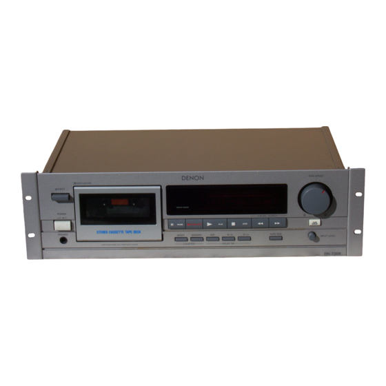
DN-730R
STEREO CASSE'I-I'E TAPE DECK
-- TABLE
OF CONTENTS
--
..........................................................................................................................................................
3
BLOCK DIAGRAM
.........................................................................................................................................................
J,
LEVEL DIAGRAM
..........................................................................................................................................................
!5
...........................................................................................................................
6-7
SECTION ..................................................................................
3
SECTIONS .......................................................................................................
9-- 10
NOTE FOR PARTS LIST ...........................................................................................................................................
l'D
METER UNIT ..............................................................................................
11-13
PARTS LIST OF 3U-2063 POWER SUPPLY UNIT .................................................................................................
13
VIEW ..........................................................................................................................
14
VIEW .......................................................................................................................................................
15
....................................................................................................
16
VIEW ............................................................................
17
........................................................................................................
17
PACKING
& ACCESSORIES
.....................................................................................................................................
t7
UNIT ..................................................................................................
18
P.W. BOARD OF 3U-2063 POWER SUPPLY UNIT ...............................................................................................
19
...........................................................................................................................................
20-21
BUNDLE
DIAGRAM
....................................................................................................................................................
2:1
DIAGRAM .....................................................................................................................................................
22
DIAGRAM .............................................................................................................................................
,!'.3
NIPPON
COLUMBIA
CO.. LTD.
Advertisement
Table of Contents

Related Manuals for Denon DN-730R


Summary of Contents for Denon DN-730R
-
Page 1: Table Of Contents
P.W. BOARD OF 3U-2063 POWER SUPPLY UNIT ... SEMJCONDUCTORS BUNDLE DIAGRAM WIRING DIAGRAM ... SCHEMATIC DIAGRAM ... NIPPON SERVICE MANUA DN-730R -- TABLE OF CONTENTS SECTION ... SECTIONS ... METER UNIT ... VIEW ... EXPLODED VIEW ... UNIT ... COLUMBIA... - Page 2 ON--730R...
-
Page 3: Specifications
(3U) design styling subject change Pro headroom extension manufactured Laboratories Licensing Corporation. 1313 and "HX PRO" are trademarks Corporation. with use of DENON DX and HD Series cassette DN--730R... - Page 4 [ _BLO cK DI_A_G_B_A_M_...
- Page 5 TCC-'30 400Hz 200nwbzm OdB=775mV DOLBY SYSTEM SENSE )rPr208) -15d£ (NORMS, -24¢JB O_B:Z7§mV HEA[',)PHONE PHONES iC306 LINE _+___, _HONES ÷TdB /J_-----Io_B L,NEO0, :, BIAS C,_10 4 -RAP HEAD (METAL) (CHROME) -_ f'dB (NORMAL) !SdB TAL) (CHROME) 21dB (NORMAL) DN-730R LCAD ,B,Q...
-
Page 6: Disassembly Instructions
i DISASSEMBLY INSTRUCTIONS How to Remove the Front Panel Remove the four screyvs, (4 X 12. CBTS-P) cover. M_ve cover to the remove Press the eject knob, open cassette cassette window as shown in the figure• Note: Handle cassette window can be scratched easily. - Page 7 HO0_ Meier Circuit Board How to Remove the Cassette Remove :the MfNI]Zf_l_PER"_etaining B and take out tl_ MINI DAMPER Hold legs of the CASSETTE pull up to remove the CASSETTE sc_ew_ ,i __ ¢smper Front surfaceofFroqtAss'y to Remove the Audio Circuit (1 } Remove...
- Page 8 DN--730R ADJUSTING CHECKING MECHANISM SECTION ReplacincTthe Pinch Roller (36) Before replacincl" tl_e pinch roller, clean o[ the pinch roller and the capstan shaft. Most causes of poor tape transport roller and capstan shaft. Remove the clips that press pinch roller forward to remove After...
- Page 9 -,--- I I -5--- Itlt __-- _--, Tope HO-7E/60 Dolby On C Level -- 20 dB From Dolby DN-730R Adjustment procedure to Figure4-2. output is 0.5 dB in relation to output. monitor conform Fig. 4-1 20_ {Mz) ---I Fig. 4-2 Level --•...
-
Page 10: Adjlisting The Electrical Sections
USES TW-2111A!2121A SONY Checking the Take-up Torque and Back Tension. TY-2231 SONY Checking the FF and REW Torque. GR-2/60 DENON Checking the FF and REW Times. TCC-153 A-BEX Adjusting the Azimuth. TY-224 SONY Checking and Adjusting the Tape Speed. TCC-130 A-BEX Adjusting the Playback Level. -
Page 11: Parts List Of 3U-2584 Audio Meter Unit
PARTS LIST OF GU-2778 AUDIO/METER UNIT Ref. No. Part" No. Part Name SEMICONDUCTORS GROUP IC301 262 0590 TCUPC1330HA IC302 262 08__006. IC UPC45706 rC303 263 0720 004/IC HA12170NT IC304 263 g56'5 007_'1 IC BA15218 IC306 263 6711 000 _ IC M5218AP IC307 263 0354 IC UPC1297CA... - Page 12 mBI D N-730R Ref. No. - Part No. R253 247 0009 Chip 1OK ohm R256 247 0005 905 1 Chip 100 ohm R257 24t 73014 987 / Chip 1M ohm R260 "247 0010"961 / Chip 22K ohm R281 247 0012 927 J Chip lOOK ohm R262...
-
Page 13: Parts List Of 3U-2063 Power Supply Unit
Re1. No. art" No. Part Name XT501 399 0107 : Ceramic Oscillator 393 8002 _FL Tube SW610, PL601 612,' 212 5604_910 Tac! Switch 614, 616, I 620, 622, i 624, 626, 628, 630, 632, 634, 636, 638, JK301 I 204 8261 , 4P Pin Jack JK302 : 204 8264... -
Page 14: Parts List Of Exploded View
E)N--730R PARTS LIST OF EXPLODED VIEW Ref. No. " Part No. 1000 652 i CHASSIS 1000 681j CHASSIS 41 l. 1000 665 ! CHASSIS 412 _'523 115 EARTH 0787"107 BOTTOM 3:38 0168 CASSE]-FE 2OO8 012 BUSHING 414 0637 SHIELD 104 0208:2.1:42 •FOOT #UDI0/METEB GU 27,38... -
Page 15: Exploded View
EXPLODED VIEW WARNING: Parts marked with this symbol Use ONLY replacement parts recommended by the manufacturer. DN-730R _ have critical characteristics. -
Page 16: Exploded View Of Casseq-I-E Mechanism
_DN-730R EXPLODED VIEW OF CASSETTE MECHANISM •... -
Page 17: Parts List Of Casseqq-E Mechanism Exploded View
PARTS LIST OF CASSEI-[E MECHANISM EXPLODED PARTS LIST OF PACKING & ACCESSORIES VIEW Ref. No. Ref. No. Part No. Part Name Remarks 9DF 5170 49 IDLER 9DF 5642 85 REEL MOTOR 9DF 6121 51 CHASSIS BASE 9DF 6230 37 REEL BASE 9DF G156 11A SCREW 2.6 ×... -
Page 18: Board Of 3U-2584 Audio/Meter Unit
UN-73ON Lp.w. BOARD OF GU-2778 AUDIO/METER UNIT _I ,°.°°... -
Page 19: Board Of 3U-2063 Power Supply Unit
2. Parts used are marked O, ]:)arts not used --. Power Trans Ref.No. i Areas part No. Europe (E2) 2335985005 U.K. (EK) Multi.Voltage (El) 23:35760000 U.S.A. & Canada (E3) 2335758009 DENON 3U-2605 2222603005 JV904 E 1 (240V) Jvg03 EU.EC.EA.EK SW902 VOLTAGE SELEC-OR Voltage JV901 JV903 Selector FUSE F901... -
Page 20: Semjconductors
E)N-730R SEMICONDUCTORS • IC -, E_ Bou, • M15218AP • pPC4570C • TL4558 NclT 8'-_ VCC X24C00S NcIT ----I SCL VSS E • X24('00S • #PC1330HA --,,,j---- vST[Z _'cc • V IN(R) I I_ PHI_ CIN1E C OU _r 1 [_ v OUT _2_]V 01. - Page 21 • I ransistors • 2SA933 • • 2SC2603 • _NuJT • 2SC1740 v OUT 1 E vzt_" v_ r; RIN E VCC 1 E _(E) VCC2 v OUT2 • DTA143ES • DTA144WS 1: Emitter Collector • BA6109U1 Base (2) R, _----t--I_ -°(c) (BI R_¢...
-
Page 22: Wiring Diagram
/DN-730R L WIRING DIAGRAM REC/PB _,_q.._ HEAD REC/PB .._.._ HEAD HEAD REEL MOTOR CAPSTAN MOTOR CASSETTE MECHANISM UNIT SENSE SENSE CHROME PACK METAL LINE IN LINE OU_ JK301 CN301 GU-2778-1 AUDIO P.W.B W151 REEL (REW) REEL (FF) SOLENOID (-) CAPSTAN (-) -
Page 23: Schematic Diagram
SCHEMATIC DIAGRAM REC/PB HEAD R372 DTC,43ES F L60 FIP6BGM6 LiO_ MpXIF ILTER • 7/35 _i4o ,o/5o 2SK3_I[B/C] Ct22 R133 RiS9 C307 JOmper _.O/1G Jumper R233 R28g 28K38t[B/C] I0303 0303 Ri99 HAI2i7ONT R299 J304 ::j= TRIDS, 20B, I09,209 :DTCZi4TS C_65 C222 t0/50 Z0304. - Page 24 DN-730RI...
- Page 25 DENON...