Table of Contents
Advertisement
Available languages
Available languages
Operator's Manual
CRRFISMRN °
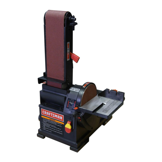
4 x 36" Belt
6" Disc
SANDER
Model No.
351.215141
CAUTION:
Read and follow
all Safety Rules and Operating
Instructions
before First Use
of this Product. Keep this
manual with tool.
Sears, Roebuck and Co., Hoffman
Estates, IL 60179 U.S.A.
www.sears.com/craftsman
30657.00 Draft (04/07/09)
Advertisement
Table of Contents

Related Manuals for Craftsman 21514 - Belt & Disc Sander


Summary of Contents for Craftsman 21514 - Belt & Disc Sander
- Page 1 6" Disc SANDER Model No. 351.215141 CAUTION: Read and follow all Safety Rules and Operating Instructions before First Use of this Product. Keep this manual with tool. Sears, Roebuck and Co., Hoffman Estates, IL 60179 U.S.A. www.sears.com/craftsman 30657.00 Draft (04/07/09)
- Page 2 TOOL wires of the extension cord should be of the correct gauge. If this Craftsman tool fails due to a defect in material or work- ° Keep visitors at a safe distance from work area. manship within one year from the date of purchase, call 1- °...
- Page 3 • Turn machine off if it jams. Belt jams when it digs too • Combination Square deeply into workpiece. (Motor force keeps it stuck in the • Phillips Screwdriver work.) MOUNT SANDER • Support workpiece with miter gauge, belt platen or work table.
- Page 4 • Center the abrasive disc onto the aluminum disc and press on firmly and evenly. Replace disc cover. Figure 6 - Using Table with Belt Figure 4 - Remove Cover and Attach Abrasive Disc Refer to Figures 7, 8 and 9, pages 4 and 5. ATTACH TABLE Refer to Figures 5 and 6.
- Page 5 Receptacle DESCRIPTION Figure 8 - 2-Prong Receptacle with Adapter The Craftsman Belt and Disc Sander is constructed of rugged die cast aluminum and cast iron providing stability and vibra- Do not use a 3-prong to 2-prong grounding adapter unless tion-free operation. The belt and disc are used to sand, permitted by local and national codes and ordinances.
- Page 6 WARNING: Operation of any power tool can result in foreign objects being thrown into the eyes, which can result in severe eye damage. Always wear safety goggles complying with United States ANSI Z87.1 (shown on package) before com- mencing power tool operation. Safety goggles are available at Sears retail stores or catalog.
- Page 7 • Tilt belt assembly to desired position. Secure belt assembly position by tightening socket head bolt in pivot bracket. • Adjustable positive stops are provided for both horizontal and vertical positions. NOTE: The horizontal limit stop is located on top of the base and the vertical limit stop is located beneath belt cover.
- Page 8 • Remove old abrasive disc by peeling it from the aluminum disc. Removing aluminum disc is not necessary. • Clean aluminum disc if necessary. Select the desired abra- sive disc and apply to aluminum disc. • Additional abrasive discs are available (See Recommended Accessories, page 13).
- Page 9 SYMPTOM CORRECTIVE ACTION POSSIBLE CAUSE(S) Motor will not start 1. Low voltage 1. Check power line for proper voltage 2. Open circuit in motor or loose 2. Inspect all lead connections on motor for loose or connections open connection 3. Defective switch 3.
- Page 10 Model 351.2151 41 Figure 17 - Replacement Parts Illustration for Belt Housing ,..b...
- Page 11 PART NO. DESCRIPTION QTY. iiO. PART NO. DESCRIPTION QTY. 23682.00 Side Cover STD840508 5-0.8mm Hex Nut* STD870516 5-0.8 x 16mm Socket Head Bolt* 23683.00 Dust Deflector STD863510 5-0.8 x 10mm Pan Head Screw* 08685.00 4-0.7 x 15mm Pan Head Screw Platen STD870510 5-0.8 x 10mm Socket Head Bolt*...
- Page 12 Model 351.21 5141 Figure 18 - Replacement Parts Illustration for Motor and Disc ,,,,,.L...
- Page 13 PART NO. DESCRIPTION QTY. PART NO. DESCRIPTION QTY. 23652.00 23666.00 Line Cord Hook Miter G auge A ssembly Knob STD870510 5-0.8 x 10ram Socket Head Bolt* 23653.00 23654.00 Locking H andle Body STD851006 6ram Flat W asher* 23668.00 Bolt 23655.00 Table 23669.00 Rubber Pad...
- Page 14 • Mantenga el Area de trabajo limpia. Las Areas de trabajo GARANTIA COMPLETA DE UN ANO PARA HERRAMIENTA desordenadas atraen accidentes. CRAFTSMAN • No use herramientas mecanicas en ambientes peligrosos. Siesta herramienta Craftsman fallara por causa de defectos en el...
- Page 15 • Mantenga todas las partes listas para funcionar. Revise el La lijadora viene montada como una unidad. Es necesario protector u otras piezas para determinar si funcionan correcta- Iocalizar y tomar en cuenta las piezas adicionales que deben mente y hacen el trabajo que deben hacer.
- Page 16 INSTALACION DE LA MESA Consulte las Figuras 5 y 6. El mesa incluido se utiliza con ambos, el disco y la correa. Para utilizar la mesa con el disco: • Coloque la mesa en la protecci6n del disco y fije con las perillas.
- Page 17 las Normas para Instalaciones Electricas (National Electric Code) y los c6digos y regulaciones locales. ADVERTENClA: Esta tarea deber_, ser realizada por un Consulte las Figuras 7, 8 y 9 en las p_.ginas 17 y 18. electricista calificado. Se puede usar temporalmente un adaptador de 3 puntas a 2 FUENTE...
- Page 18 DESCRIPClON miento antes de comenzar a lijar o esmerilar. La Lijadora de correa y disco de Craftsman est,. construida • AsegLirese que el disco gire en el sentido de las manillas aluminio...
- Page 19 • Afloje el perno de cabeza hueca que est,. roscado en la pieza de soporte de pivote. • Incline el conjunto de la correa a la posici6n deseada. Apriete el perno de cabeza hueca en la pieza de soporte de pivote para fijar la posici6n del conjunto de la correa.
- Page 20 PARA LIJAR LA CORREA EN POSIClON • Mueva la pieza de trabajo a trav6s del lado inferior (izquierdo) HORIZONTAL Y EL TOPE DE SEGURIDAD INSTALADO del disco abrasivo. Sujete firmemente la pieza de trabajo con las dos manos; mantenga los dedos alejados del disco Consulte la Figura 13.
- Page 21 • Vuelva a montar en el orden inverso. ADVERTENCIA: AsegtJrese de que la unidad est6 desconecta- da de la fuente de alimentaci6n electrica antes de tratar de dar servicio o retirar cualquier componente. LIMPIEZA Mantenga la m_tquina y el taller limpios. No permita que el aserrin se acumule...
- Page 22 SINTOMA MEDIDA CORRECTIVA CAUSA(S) POSIBLE(S) El motor no arranca 1. Voltaje bajo 1. Verifique el voltaje correcto de la linea de alimentaci6n 2. Circuito abierto en el motor o 2. Inspeccione todas las conexiones de conductores conexiones sueltas en el motor para ver que no haya conexiones sueltas o abiertas 3.
- Page 23 NOTAS...
- Page 24 Your Home For expert troubleshooting and home solutions advice: www.managemyhome.com For repair - in your home - of all major brand appliances, lawn and garden equipment, or heating and cooling systems, no matter who made it, no matter who sold it! For the replacement parts, accessories owner's manuals that you need to do-it-yourself.