YORKVILLE E10P Service Manual
Hide thumbs
Also See for E10P:
- Owner's manual (20 pages) ,
- Service manual (19 pages) ,
- Brochure (1 page)
Table of Contents
Advertisement
Quick Links
SERVICE MANUAL
MODEL TYPE: YS1066
E10P
WEB ACCESS: http://www.yorkville.com
WORLD HEADQUARTERS
CANADA
U.S.A.
Yorkville Sound
Yorkville Sound Inc.
550 Granite Court
4625 Witmer Industrial Estate
Pickering, Ontario
Niagara Falls, New York
L1W-3Y8 CANADA
14305 USA
Voice: (905) 837-8481
Voice: (716) 297-2920
Fax: (905) 837-8746
Fax: (716) 297-3689
Quality and Innovation Since 1963
Printed in Canada
Manual-Service-e10p-00-1v1 • Jun 24, 2009
Advertisement
Table of Contents

Related Manuals for YORKVILLE E10P


Summary of Contents for YORKVILLE E10P
-
Page 1: Service Manual
SERVICE MANUAL MODEL TYPE: YS1066 E10P WEB ACCESS: http://www.yorkville.com WORLD HEADQUARTERS CANADA U.S.A. Yorkville Sound Yorkville Sound Inc. 550 Granite Court 4625 Witmer Industrial Estate Pickering, Ontario Niagara Falls, New York L1W-3Y8 CANADA 14305 USA Voice: (905) 837-8481 Voice: (716) 297-2920... -
Page 2: Important Safety Instructions
IMPORTANT SAFETY INSTRUCTIONS This lightning flash with arrowhead symbol, within The exclamation point within an equilatereal triangle is an equilateral triangle, is intended to alert the user to intended to alert the user to the presence of important the presence of uninsulated “dangerous voltage” operating and maintenance (servicing) instructions in within the product’s enclosure that may be of sufficient the literature accompanying the appliance. - Page 3 e10p Parts List 6/24/2009 YS # Description Qty. YS # Description Qty. YS # Description Qty. 5906 RED 3MM LED 1V9 20MA.4SPCER T&R 8742 4-40 X 3/8 PAN PH TAPTITE JS500 7876 __2U2 200V 20%CAP 3025 SMT CER 5907 YEL 3MM LED 1V9 20MA.4SPCER T&R 8946 4-40 X 5/16 FLAT PHIL U/C TRILOB ZC 7877 __2U2 100V 20%CAP...
- Page 4 E 1 0 P B l o c k D i a g r a m D E S I G N E D & M A N U FA C T U R E D B Y Y O R K V I L L E S O U N D ±44V ±22V INPUT Horn Driver...
-
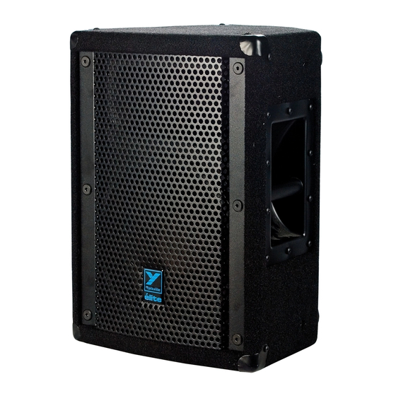
Page 5: Specifications
Specifications E10p Model: powered loudspeaker System Type: Active Active or Passive: Program Power (Watts): Internally biamped Biamp Operation Only: 65 to 20k Frequency Response (Hz +/- 3db): 1500 Crossover Frequency (Hz): 2 way Driver Configuration: 1 inch HF Driver(s): HF Program Power (Watts): HF Impedance (ohms): 100 x 25 HF Dispersion (°H x °V):... - Page 6 {Voltage} 10V0 W125 W125 270P 10V0 {Voltage} INPUT 17K80 1K00 0805 0805 W125 30K00 {Body} W125 J3:A 10K00 0805 FUNCTION 3440 W125 NE5532D +1/4 1K800 {Function} DOWN {Body} U4:A S4:C XLR/1/4in U4:B MIC IN/OUT SWITCH 1/4in&XLR PCB MT VERT COMBO NE5532D J3:B 1K800...
-
Page 7: Low Voltage Supply
100N 100N 100N 100N 100N 100N SOT23 W12:A W11:A +1V8 SUPPLY 475R0 7805 0805 W12:B W11:B MMBT3906LT1 {Function} W12:C W11:C 100N W125 270R W12:D W11:D 1K00 N.C. 0805 0805 100N 100N 7894 W12:E W11:E 100N 100N 1/8W {Function} OSCILLATOR 8200NH 200R W12:F W11:F... -
Page 8: Power Supply
MUTE ON/OFF PCB MALE CONNECTORS SOT-23 7837 W125 W125 POWER SUPPLY 0805 0805 MMBT5401 -20V UNMUTE 0805 MALE 9 PIN CONNECTOR FOR FUSE TRANSFORMER SECONDARYS IEC_RECT N.A.: #2410 F 4A W6:L CDSF4148 CE: #2470 F2A CDSF4148 FUSE 18AWG W3:A 9 DPDT Switch W6:X W30:A... - Page 9 5989 R T V C102 270R R T V R T V R T V 1300UH 6492 R T V E10P/E12P YORKVILLE E10P/E12P M1311 V2.00 GROUND M1311 W33 G/Y v2.00 R T V CLINCH INSERT ORIGIN Top Assy M1311v2.00 LONG AXIS...
- Page 10 SEE LAYOUT DIAGRAM M1311 PRODUCTION NOTES 1. ADD RTV BETWEEN C106, C112 AND W30 THE POWER CONNECTOR 2. ADD RTV UNDER J3 XLR. 3. B.A. DO NOT STUFFED S2 AND LD1. 4. B.A. CHECK PAGE 4 FOR W3 AND W33 POWER CONNECTORS. 5.
- Page 11 SEE PRODUCTION NOTES M1311.PCB_DATABASE_HISTORY MODEL(S):- E10P DATE VER# DESCRIPTION OF CHANGE 21-APR-2008 1.00 FIRST DESIGN 28-AUG-2008 1.01 PC7634 - replace R67, R68, and R47 with 475R #7940 25-MAR-2009 2.00 PC7640-replace R67, R68 and R47 with 8U2 #7941 and 200R #7708. Also made afew pcb changes for production...
- Page 12 5989 R T V C102 270R R T V R T V R T V 1300UH 6492 R T V E10P/E12P YORKVILLE E10P/E12P M1311 V2.00 GROUND M1311 W33 G/Y v2.00 R T V CLINCH INSERT ORIGIN Top Assy M1311 v2.00...
- Page 13 WOOFER 325W NON INVERTING CLASS D AMPLIFIER W125 1/8W W125 W125 560R 0805 0805 0805 0805 W125 470P 100K MMBT5401 0805 1/8W W125 7837 1206 0805 SOT-23 W125 0805 MC33078D W125 MC33078D U2:C 560R 470P AUDIO IN 0805 U2:A U2:B 7851 LM311 0805...
- Page 14 26 PIN MALE HEADER 30 WATT HORN POWER AMP W1:Z W500 10V0 {Voltage} W1:Y 2010 IRF530NS W250 W1:X 100R CMPD914 7840 0805 W500 D2PAK W1:W W500 15V0 0805 2010 2010 {Voltage} W1:V 270R MURA240T3 0805 W1:U W1:T MMBT5401 {Function} W1:S MJD243T4G {Function} {Function}...
- Page 15 WASHER #8961 ON ALL 4 100N -15V REGULATOR -15V REGULATOR +15V REGULATOR +15V REGULATOR CORNER MOUNTING NUTS HORN MJB41C MJD243T4G IRF530NS YORKVILLE SOUND OUTPUT HORN SIGNAL 2 OZ. COPPER HORN 470P 470P 7846 MC7815BDTG MC79M15CDTG THERMAGON WITH ALUMINUM SUBSTRATE MAKE SUBSTRATE NEXT THICKER MATERIAL...
- Page 16 WASHER #8961 ON ALL 4 100N -15V REGULATOR -15V REGULATOR +15V REGULATOR +15V REGULATOR CORNER MOUNTING NUTS HORN MJB41C MJD243T4G IRF530NS YORKVILLE SOUND OUTPUT HORN SIGNAL 2 OZ. COPPER HORN 470P 470P 7846 MC7815BDTG MC79M15CDTG THERMAGON WITH ALUMINUM SUBSTRATE MAKE SUBSTRATE NEXT THICKER MATERIAL...