Table of Contents
Advertisement
Quick Links
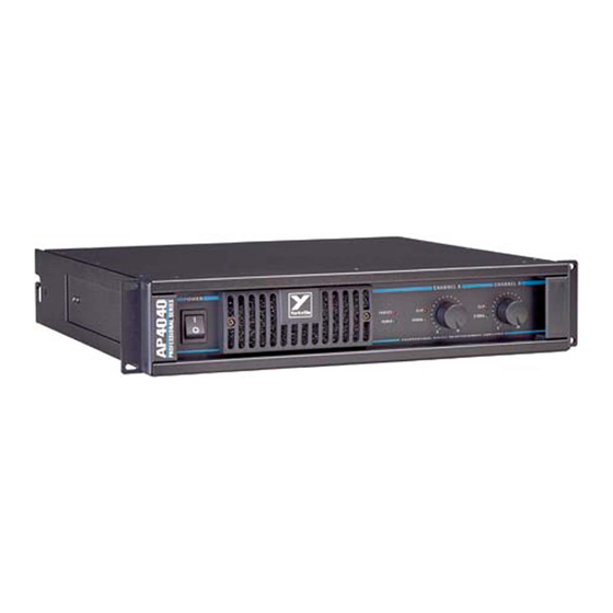
AP4040
WEB: www.yorkville.com
WORLD HEADQUARTERS
CANADA
U.S.A.
Yorkville Sound
Yorkville Sound Inc.
550 Granite Court
4625 Witmer Industrial Estate
Pickering, Ontario
Niagara Falls, New York
L1W-3Y8 CANADA
14305 USA
Voice: (905) 837-8481
Voice: (716) 297-2920
Fax: (905) 837-8746
Fax: (716) 297-3689
MODEL TYPE: YS4040
SERVICE MANUAL
Quality and Innovation Since 1963
Printed in Canada
Manual-Service-ap4040-00-4v0.pdf
Advertisement
Table of Contents

Related Manuals for YORKVILLE Professional AP4040


Summary of Contents for YORKVILLE Professional AP4040
-
Page 1: Service Manual
AP4040 WEB: www.yorkville.com WORLD HEADQUARTERS CANADA U.S.A. Yorkville Sound Yorkville Sound Inc. 550 Granite Court 4625 Witmer Industrial Estate Pickering, Ontario Niagara Falls, New York L1W-3Y8 CANADA 14305 USA Voice: (905) 837-8481 Voice: (716) 297-2920 Fax: (905) 837-8746 Fax: (716) 297-3689... -
Page 2: Power Sources
IMPORTANT SAFETY INSTRUCTIONS This lightning flash with arrowhead symbol, within The exclamation point within an equilatereal triangle is an equilateral triangle, is intended to alert the user to intended to alert the user to the presence of important the presence of uninsulated “dangerous voltage” operating and maintenance (servicing) instructions in within the product’s enclosure that may be of sufficient the literature accompanying the appliance. - Page 3 AP4040 Parts List 3/17/2010 YS # Description Qty. YS # Description Qty. YS # Description Qty. YS # Description Qty. 5906 RED 3MM LED 1V9 20MA.4SPCER T&R 5896 4700U 80V 20%CAP BLK 25X50MM ELS 4986 1/4W 270R 5%MINI T&R RES 8869 8-18 X 1/2 THRD CUTTING FOR PLASTIC 5908 GRN 3MM LED 1V9 20MA.4SPCER T&R...
- Page 4 SERVICE MANUAL SERVICE MANUAL Yorkville Sound • http://www.yorkville.com Yorkville Sound • http://www.yorkville.com The activity LED circuit consists of Q1 and the surrounding circuitry. The audio sig- Y Y o o r r k k v v i i l l l l e e A A P P 4 4 0 0 4 4 0 0 P P o o w w e e r r A A m m p p l l i i f f i i e e r r nal enters the activity LED circuit through R2.
- Page 5 SERVICE MANUAL SERVICE MANUAL Yorkville Sound • http://www.yorkville.com Yorkville Sound • http://www.yorkville.com CIRCUIT DESCRIPTION: The voltage amplifier is a mirrored image with circuitry connected to the positive power supply rail being identical (but opposite polarity) to the circuitry connected to the nega- tive power supply rail.
- Page 6 SERVICE MANUAL SERVICE MANUAL Yorkville Sound • http://www.yorkville.com Yorkville Sound • http://www.yorkville.com amount of time was spent on the current limit circuitry so that it may simulate the safe This causes Q40 to turn off until the reduced current flowing through Q5 maintains operating area of the output transistors (SOAR curve).
- Page 7 SERVICE MANUAL SERVICE MANUAL Yorkville Sound • http://www.yorkville.com Yorkville Sound • http://www.yorkville.com If prolonged current limiting occurs on the amplifier’s output transistors then D204 or D205 (depending on which channel is current limiting) will be forward biased turning on NOTE: Every time you replace blown output transistors on a Q202 (from its off state).
- Page 8 SERVICE MANUAL SERVICE MANUAL SERVICE MANUAL SERVICE MANUAL SERVICE MANUAL SERVICE MANUAL Yorkville Sound • http://www.yorkville.com Yorkville Sound • http://www.yorkville.com Yorkville Sound • http://www.yorkville.com Yorkville Sound • http://www.yorkville.com Yorkville Sound • http://www.yorkville.com Yorkville Sound • http://www.yorkville.com Yorkville Sound • http://www.yorkville.com Yorkville Sound •...
-
Page 9: Service Bulletin
AP4040 Quick Fix for M1146 & M1126 To speed up the servicing of the AP4020 or AP4040 on your bench, Yorkville Sound’s service department has developed a method to replace the compo- nents most likely to fail when a M1146 amplifier board requires service. - Page 10 SERVICE BULLETIN SERVICE BULLETIN AP4020 & AP4020 & AP4040 AP4040 STEP 6. Measure across the pair of test points shown in the component Testing Repaired Circuit Boards layout listed in the table below. If the measured value is not Now that you have rebuilt the M1146 or M1126 circuit board. It is just as within + or –...
- Page 11 BC560C TO92 1N750ARL 5102 470N BC560C * NOTE: MINI 1/4W MPSA63 M1128 - FOR R34 NAD R47 USE #4821 470R 5102 4148 1/4W MINI M1133 - FOR R34 AND R47 USE #4808 2K TO92 MINI 220N 1/4W FLMP 5106 1/4W 249R 1/8W TO92...
- Page 12 M1128 AP-VX RCLP LVGND M1128 AP-VX M1133 PRTCT 21in 14C 100K 2329 3604 To Power Supply Pcb BC560C 100K 220P 470R 470R 470N 220P 4148 470K Channel A Channel B MPSA63 R Clip 470K 620R R136 R Activity R55A 220R 14K7 4148 5908...
- Page 13 SEE LAYOUT DIAGRAM X8011 PRODUCTION NOTES - M1128 AP/VX 3511 8870 WASHER SCREW SPACER PT#3739...
- Page 14 SEE LAYOUT DIAGRAM X8011 PCB_DATABASE_HISTORY X8011 DRILL HISTORY MODEL(S):- MODEL(S):- AP4020 AND AP4040/VX2400 AND VX2402/V42 AND V44 AP4020 AND AP4040/VX2400 AND VX2402/V42 AND V44 DATE VER# DESCRIPTION OF CHANGE DATE VER# DESCRIPTION OF CHANGE LEAD/PIN REFERENCE OCT/97 1.00 FIRST PRODUCTION APR/17/98 2.00 #5664 RIBBON CABLE CONNECTIONS CHANGED FOR...
- Page 15 U3:A MC33078P 220P 100V 1/4W 1/4W 1/4W FILTER SW 1K54 9K76 9K76 68N 100V 68N 100V 0.1% 0.1% LINE XLR U4:A S1:B 150N 63V 150N 63V MC33078P 1/4W 120K 220P 100V LIMITER 1/4W 1/4W 1/4W 1K54 9K76 9K76 0.1% 0.1% S2:A MONO-STEREO-BRIDGED S3:A...
- Page 16 3417 CM CC 3436 3436 BRIDGED - STEREO - MONO R112 150N R109A 3436 R111 R109B 150N 100N 100N 4148 LSPRE RSPRE 14 PIN SCKT MC33078P 4148 10K0 9K76 220P 9K76 100N 220P 100N 100N 220P 220P 220P 220P 1K54 1K54 LINE XLR TIP-SW...
- Page 17 M1129.sch_schematic-DATABASE_HISTORY M1129 DRILL HISTORY MODEL(S):- AP4020 / AP4040 / AP2020 / AM1CE MODEL(S):- AP2020/AP4020/AP4040/AM1CE DATE VER# DESCRIPTION OF CHANGE DATE VER# DESCRIPTION OF CHANGE OCT/1997 1.00 FIRST PRODUCTION APR-03-2003 V06 NOV/12/97 2.00 REVERSED INPUT POLARITY. MODIFIED FOR AP2020 AUG-15-2005 V07 CONVERT TO PCAD2002 DEC/02/97 C27, C28, C29, C30 TO 150n...
- Page 18 6880 6880 4N35 4N35 U1:B U1:A ZD10 1/4W 1N750ARL 220R MINI J1:A Function SPEAKON 4C 3628 1/4W 1/4W 250V 400V 620R W1:H IRF630NPBF W1:G 3628 SPEAKON 4C 6752 5.0W TO220 Function W1:F MR854 Function J1:B MJ21196 MJ21196 MJ21196 MJ21196 200V 220P BC550C W1:E...
- Page 19 ETCH INTO WAVE GUIDE ETCH GUIDE MR854 MR854 MR854 MR854 MR854 MR854 MR854 MR854 6874 6873 STM-BTB-600BRG MJE350 MJE340 6752 6925 7004 7005 MTP8P20 2SA2121-0 2SC5949-0 TO126 TO126 TO220 TO220 TO3P TO3P 1/2W 1/2W 1/2W 1/2W 200R0 TO92 MBS4992 EY10 470R BAV21 200R0...
- Page 20 SEE LAYOUT DIAGRAM M1146 - AP4040 / V44 PRODUCTION NOTES 4. MOUNTING HARDWARE FOR Q11,Q12 #8741 4-40X 1/2" BOLT 1. MOUNTING DETAILS FOR 5W ADD #8629 SPACERS ONLY ON 5 WATT RESISTORS R29 AND R45. ENSURE SPACERS ARE UNDER 8. TAB WIRE COLOURS: TAB 1 RED 16AWG TAB 2 YEL 16AWG RESISTOR BODY ENOUGH TO RAISE IT OFF THE BOARD SURFACE.
- Page 21 SEE LAYOUT DIAGRAM 2N5401 M1146 Database History M1146.SCH_DATABASE_HISTORY 2N5551 MODEL(S):- 2N6517 AP4040 / V44 MODEL(S):- AP4040 MPSA13 DATE VER# DESCRIPTION OF CHANGE DATE VER# DESCRIPTION OF CHANGE MPSA43 BC550C FEB/12/98 1.00 DERIVED FROM M1126 APR/25/06 PC#7007 MAC-224-4 TO STM-BTB-600BRG AS35 MBS4942 MPSA56 JUN/19/98...
- Page 22 C214A 220P 100V R203A 1/4W 10K0 MINI W35:A W35:B R201A C201A 1/4W MC33078P W35:C 16K5 DPDT Switch GENERIC_XF_2S_1P W35:D R202A WHITE 1/4W U201:A Thermal Breaker 16K5 W35:E R204A BLACK 1/4W W35:F 10K0 MINI W35:G C214B 220P 100V W35:H R203B W35:I 1/4W 10K0 R201B...
- Page 23 StepAndRepeat - X2@6.675Y1@0.000 M1147 AP4040 XFMR XF SEC MID 6451 BRIDGE C208 C207 C210 C209 BRIDGE MOUNTED 100V 100V 330U 330U BY WIRING TOP AMP 6419 D205 4148 D204 4148 PC-C TO BOTTOM 2328 2328 Q240 Q241 C202B RELAY 1A C201B 10K0 C215...
- Page 24 SEE LAYOUT DIAGRAM M1147 AP4040 X8012 PRODUCTION NOTES: 1. FOR C1 USE 22N FOR NORTH AMERICAN AND 680N FOR EURO. 2. ADD RTV UNDER RELAY AND BEND LEADS FLAT TO PCB. RELAY...
- Page 25 SEE LAYOUT DIAGRAM PIN CONFIGURATION X8012 Database History X8012 PCB_DATABASE_HISTORY 2N6517 MODEL(S):- MODEL(S):- AP4040 AND V44 AP4040 AND V44 2N5401 DATE VER# DESCRIPTION OF CHANGE DATE VER# DESCRIPTION OF CHANGE 2N5551 MJF6388 FEB/12/98 1.00 DERIVED FROM M1127 MPSA06 MAR/30/98 2.00 REPLACE R233&THERMISTOR WITH SURGISTORS MJF6668 MPSA13...