GE CGP650SETSS Installation Instructions Manual
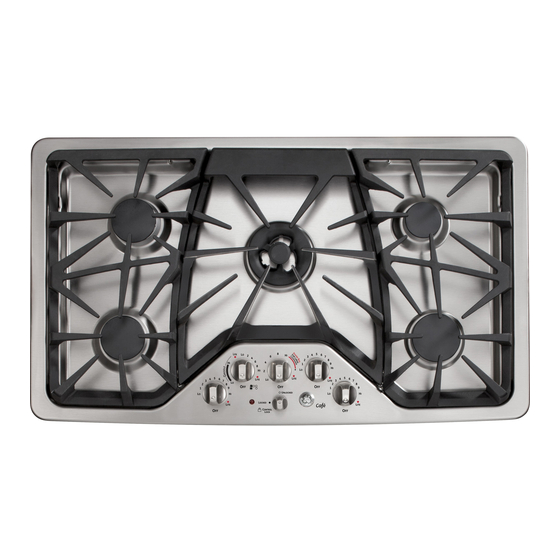
36″ sealed gas cooktop
Hide thumbs
Also See for CGP650SETSS:
- Owner's manual & installation instructions (64 pages) ,
- Installation instructions manual (49 pages) ,
- Dimensions and installation information (2 pages)
Table of Contents
Advertisement
Quick Links
Installation
Instructions
Questions? Call 800.GE.CARES (800.432.2737) or Visit our Website at: ge.com
In Canada, call 1.800.561.3344 or Visit our Website at: www.geappliances.ca
IN THE COMMONWEALTH OF
MASSACHUSETTS:
• This product must be installed by a licensed
plumber or gas fitter.
• When using ball-type gas shut-off valves, they
shall be the T-handle type.
• A flexible gas connector, when used, must not
exceed 3 feet.
BEFORE YOU BEGIN
Read these instructions completely
and carefully.
IMPORTANT
•
for local inspector's use.
IMPORTANT
•
codes and ordinances.
• Note to Installer – Be sure to leave these
instructions with the Consumer.
• Note to Consumer – Keep these instructions for
future reference.
• Product failure due to improper installation is not
covered under the Warranty.
WARNING
properly grounded.
IMPORTANT
•
appliance shall be conducted according to the
manufacturer's instructions.
• Proper installation is the responsibility of the
installer and product failure due to improper
installation is NOT covered under warranty.
WARNING
power at the main circuit breaker
or fuse box before installing.
31-10808 (07-11 GE)
— Save these instructions
— Observe all governing
— This appliance must be
— Leak testing of the
— Disconnect all electrical
36" Sealed Gas Cooktop
PGP976, PGP986, CGP650
FOR YOUR SAFETY:
WARNING
manual is not followed exactly, a fire, explosion
or gas leak may result causing property damage,
personal injury or death.
Do not store or use gasoline or other flammable
vapors and liquids in the vicinity of this or any
other appliance!
• Do not try to light any appliance. Do not touch
any electrical switch; do not use any phone in
your building.
• Immediately call your gas supplier from a
neighbor's phone. Follow the gas supplier's
instructions.
• If you cannot reach your gas supplier, call the
fire department.
Installation and service must be performed by
a qualified installer, service agency or the gas
supplier.
This cooktop has been certified by UL. You'll find
safety precautions in your Owner's Manual. Read
them carefully.
• Installation of this cooktop must conform with
local codes or in the absence of local codes with
the National Fuel Gas Code, ANSI Z223.1/NFPA
54–Latest edition.
• Be sure your cooktop is installed properly by a
qualified installer or service technician.
• To eliminate reaching over surface burners,
cabinet storage above burner should be avoided.
• Do not install the unit near an outside door or
where a draft may affect its use.
1
— If the information in this
WHAT TO DO IF YOU SMELL
GAS:
Advertisement
Table of Contents

Related Manuals for GE CGP650SETSS


Summary of Contents for GE CGP650SETSS
- Page 1 Installation 36″ Sealed Gas Cooktop Instructions PGP976, PGP986, CGP650 Questions? Call 800.GE.CARES (800.432.2737) or Visit our Website at: ge.com In Canada, call 1.800.561.3344 or Visit our Website at: www.geappliances.ca FOR YOUR SAFETY: IN THE COMMONWEALTH OF MASSACHUSETTS: WARNING — If the information in this •...
-
Page 2: Important Safety Instructions
Installation Instructions IMPORTANT SAFETY INSTRUCTIONS ELECTRICAL REQUIREMENTS PARTS INCLUDED This appliance must be supplied with the proper voltage and frequency and connected to an individual, properly grounded branch circuit, protected by a circuit breaker or fuse having 2 Screws Regulator amperage as noted on the rating plate. -
Page 3: Pre-Installation Checklist
Installation Instructions PRE-INSTALLATION CHECKLIST When preparing cooktop opening, make Remove Installation Instructions from sure the inside of the cabinet and the literature pack and read them carefully cooktop do not interfere with each other. before you begin. (See section on preparing the opening.) Be sure to place all literature (Owners Manual, Remove packaging materials, grate boxes, Installation Instructions, etc.) in a safe place... -
Page 4: Preparing The Opening
Installation Instructions PREPARING THE OPENING 3 CUTOUT DIMENSIONS OF COUNTERTOP 1 MAINTAIN THE FOLLOWING MINIMUM CLEARANCE DIMENSIONS To ensure accuracy, it is best to make a template when cutting the opening in the counter. 13″ MAX. Depth of overhead cabinets 19-1/8”... -
Page 5: Installing The Cooktop Unit
Installation Instructions INSTALLING THE COOKTOP UNIT 1 LOCATE ELECTRICAL OUTLET AND 4 ATTACH BRACKETS TO COOKTOP GAS SHUT-OFF VALVE BENEATH Remove the screw from the side of the cooktop CABINET and screw the hold-down bracket to the side of the cooktop unit. Repeat for opposite NEVER REUSE OLD side of cooktop. - Page 6 Installation Instructions INSTALLATION—GAS CONNECTIONS 1 PROVIDE ADEQUATE 3 INSTALL REGULATOR ONTO GAS SUPPLY BURNER BOX BOTTOM This cooktop is designed to operate on natural Screw the regulator gas at 5″ of water column manifold pressure and onto the burner 7″ of water column (W.C.) supply pressure. It is box bottom pipe shipped from the factory set for natural gas.
- Page 7 Installation Instructions 5 CHECK FOR LEAKS 6 INSTALLATION OVER BUILT-IN OVEN LEAK TESTING OF THE APPLIANCE SHALL BE CONDUCTED ACCORDING TO THE MANUFACTURER’S See built-in oven installation for complete INSTRUCTIONS. installation instructions. Before testing for leaks, make sure all burner knobs are in the OFF position.
-
Page 8: Installation-Electrical Connections
Installation Instructions INSTALLATION—ELECTRICAL CONNECTIONS WARNING — Disconnect all electrical power at the main circuit breaker or fuse box before installing. ELECTRICAL SUPPLY AND OUTLET An adequate electrical supply and outlet must be used to operate the electrical parts of your cooktop. -
Page 9: Cooktop Burners
Installation Instructions COOKTOP BURNERS 1 ASSEMBLING THE COOKTOP BURNERS The electrode of the igniter is exposed. Be careful not to turn on any cooktop controls while the top of the burner is removed. Do not remove the top or touch the electrode of any burner while another burner is turned on. -
Page 10: Burner Ignition
Installation Instructions COOKTOP BURNERS (CONT.) 3 BURNER IGNITION 5 BURNER GRATES The three cooktop grates are designed for specific Cooktop Spark Ignition—When you turn positions. For maximum stability, these grates the cooktop knob to LITE, the spark igniter makes a should only be used in their proper position with series of electric sparks (ticking sounds) which light the edges positioned on top of the black bumpers... -
Page 11: Operation Checklist
Installation Instructions OPERATION CHECKLIST Make sure all controls are left in the OFF When ordering parts, always include the serial position. Check to be sure the cooktop is in the number, model number and a code letter to UNLOCKED position (on models so equipped). ensure proper replacement parts. -
Page 12: Making The Lp Conversion
Installation Instructions MAKING THE LP CONVERSION TOOLS YOU WILL NEED 1 SAFETY INFORMATION YOU FOR LP CONVERSION SHOULD KNOW The pressure regulator and burner orifices are set Phillips-Head for natural gas. To use LP gas, the regulator and 7mm Nutdriver Screwdriver burner orifices must be converted. - Page 13 Installation Instructions MAKING THE LP CONVERSION (CONT.) 3 CHANGE COOKTOP BURNER 3 CHANGE COOKTOP BURNER ORIFICES ORIFICES (CONT.) Remove the top grates, burner caps, and burner CENTER BURNER heads. 17,000 BTU/hr Extra Large Burner (PGP976 Models) Using a 7mm nut driver, remove the top burner orifices.
- Page 14 Installation Instructions 3 CHANGE COOKTOP BURNER 3 CHANGE COOKTOP BURNER ORIFICES (CONT.) ORIFICES (CONT.) CENTER BURNER LEFT FRONT BURNER 20,000 BTU/hr Tri-Ring Burner (PGP986 and CGP650 (PGP986 and CGP650 Models) Models) Griddle Screw Orifice spuds located through these The griddle screw is marked with N openings.
- Page 15 Installation Instructions MAKING THE LP CONVERSION (CONT.) 4 ADJUST BURNER FLAMES Testing Flame Stability: Test 1 – Temporarily replace knobs. Turn the Turn all burners full on and check the flames. knob from “HI” to the lowest setting They should be blue in color with some yellow quickly.
- Page 16 Notes.
- Page 17 Notes.
- Page 18 réglage. lors à positionné être doit plaque contrôle plaque. contrôle lors gauche avant anneaux trois à sauf brûleur pour brûleurs tous Pour gauche arrière brûleur pour naturel. fonctionne appareil réglage, autres signaler pour l’étiquette enlevez deux doté tige naturel, appareil votre reconvertissez vous...
- Page 19 haut. grilles brûleur capuchons têtes, bases, place Remettez précédemment. enlevée l’aide à pression régulateur d’instructions feuille support nouveau à fixez support naturel pour diaphragmes Remettez précédentes. principal Orifice illustrations dans qu’indiqué précis Tall emplacement leur à seulement) CGP650 mijotage Orifice PGP986 modèles (sur...
- Page 20 central burner center brûleur relatives instructions instructions Voir CGP650 PGP986 modèles Pour Tall PGP976 modèles Pour cuisson. table brûleur diaphragme chaque précis l’emplacement indiquent signes haut. rien) III, gravés signes série indique diaphragme Chaque future.) utilisation pour appareil votre enlevés avez vous diaphragmes...
- Page 21 long) po., 5/32 (tête plate sécurité Lunettes tête à tournevis Petit Pinces Torx tête à Tournevis Tourne-écrou Phillips Tournevis régulateur. capuchon Revissez • claquer. faisant CONVERSION À NÉCESSAIRES OUTILS position, ressorts l’étrier Remettez • pression Régulateur DOWN FOR OFF l’étape à...
- Page 22 fabrique. départ cuisson table votre pression carburant catégorie brûleurs, cote indique elle série, modèle numéros plus cuisson. table brûleurs. boîte située cuisson sécuritaire utilisation bonne assure Cela table votre minéralogique plaque guide. instructions toutes suivi bien d’avoir assurer vous pour nouveau à...
- Page 23 noirs grille Butoirs Grille qu’illustré. noirs, butoirs dessus reposant bords leurs avec appropriée position à trouver doivent grilles stabilité, maximum assurer Pour précises. positions pour prévues sont cuisson table grilles trois BRÛLEUR GRILLES nouveau. à d’essayer avant minute brûler. vous pouvez attendez (arrêt)
- Page 24 brûleurs. tous fonctionnement vérifier pour robinets tous Essayez (allumage). LITE position l’enlever devez vous s’allume, brûleur Quand • parvient. quand s’allumer doit brûleur • s’allumera. (allumage) LITE position brûleur seul, mais, (crépitement) d’étincelles série feront allumeurs Tous (allumage). LITE position tournez-le brûleur robinet...
- Page 25 l’usage avant contact terre à mise bonne Assurez RALLONGE. N’UTILISEZ ADAPTATEUR. N’UTILISEZ D’ALIMENTATION. CORDON (TERRE) BROCHE TROISIÈME ENLEVER COUPER DEVEZ VOUS CAS, AUCUN prise. ancienne votre changer qualifié électricien à demandez triphasée, prise n’avez vous cycles. volts, normal ménager courant alimente terre, à...
- Page 26 kPa). (3,5 psig à inférieures égales test pressions à d’alimentation système pression essai à procéder avant d’alimentation tuyau système cuisson table IIsolez kPa). (3,5 psig à supérieures test pressions à système pression essai à procéder avant d’alimentation tuyau système d’arrêt robinet cuisson table...
- Page 27 filetés. raccords tous butane naturel pour approuvée filetage pour graisse mettez téflon ruban Raccord raccord. installez pression régulateur d’entrée l’extrémité pression dans tuyau section Vissez Régulateur posez gaz, fuites possibilité réduire Pour gaz. à appareil installez vous quand neufs comptoir flexibles raccords toujours...
- Page 28 documentation. trousse fixation supports Retirez MONTAGE place. PIÈCES TROUVEZ bien cuisson table tenir pour l’armoire côtés fixation supports vissez place, cuisson table fois cuisson table sous Linge cuisson table Envers protégée. surface l’envers à cuisson table Posez dégagements. comptoir. torchon serviette Placez tous...
- Page 29 (19-3/8″) (28-1/4″) (200°F) 93°C atteindre pouvant chaleru supporter pouvoir (3-1/4″) cuisson Table doivent comptoir 8-1/4 armoires mur, revêtements (30″) (21″) CUISSON TABLE DÉCOUPAGE DIMENSIONS [200°F]) 93°C ATTEINDRE (POUVANT CHALEUR SUPPORTER PUISSENT CUISSON CUISSON. SURFACE AU-DESSUS (18”) TABLE AUTOUR 45,7 MINIMALE DISTANCE S’APPLIQUER ARMOIRES...
- Page 30 cuisson. table produite (200°F)] 93°C atteindre [pouvant chaleur supporter puissent cuisson table autour armoires comptoir mur, revêtements Assurez-vous locales. ordonnances toutes à codes tous à scrupuleusement conformer vous assurez-vous maison, votre cuisson dans cuisson table votre installer Pour Table d’électricité.) besoins section (Consultez...
- Page 31 Code. Electrical Canadian exigences conformément cuisinière votre isoler câbler 1/8po foret sécurité Lunettes devez vous codes, l’absence dangereuse. électrique main à Perceuse situation provoquez vous vigueur, codes conformément cuisinière votre câblant région. votre dans vigueur électriques codes vérification publics services entreprise votre à...
- Page 32 31-10808 (07-11 d’installer. avant fusibles à boîte maison disjoncteur niveau électrique courant AVERTISSEMENT tout Débranchez — gaz. fournisseur votre service technicien qualifié, installateur faits être doivent cuisson table votre service L’installation installation. mauvaise à panne pompiers. appelez gaz, fournisseur votre aucune couvre garantie...