HP xw9400 Service And Technical Reference Manual
Hp xw9400: reference guide
Hide thumbs
Also See for xw9400:
- Hardware setup manual (56 pages) ,
- Quickspecs (47 pages) ,
- Setup manual (44 pages)
Table of Contents
Advertisement
Quick Links
Advertisement
Table of Contents
Troubleshooting

Related Manuals for HP xw9400


Summary of Contents for HP xw9400
- Page 1 HP xw9400 Workstation Service and Technical Reference Guide User Guide...
- Page 2 Warranty Trademark Credits © 2006 Copyright Hewlett-Packard Hewlett-Packard Company shall not be liable The HP Invent logo is a trademark of Hewlett- Development Company, L.P. for technical or editorial errors or omissions Packard Company in the U.S. and other contained herein or for incidental or countries.
-
Page 3: Table Of Contents
Restoring the Windows operating system ................. 19 The RestorePlus! process ................. 19 Creating a RestorePlus! CD ............. 19 Restoring from RestorePlus! CDs ............ 19 Restoring from RestorePlus! on the Recovery Partition ....19 HP Backup and Recovery Manager restore points ........... 20 ENWW... - Page 4 Ordering backup software ................. 20 Restoring the Linux operating system ................21 Downloading the latest HP driver CD contents ..........21 Installing the operating system with the HP driver CD contents ....... 21 Protecting the software ........................22 3 System management Computer Setup (F10) Utility ......................
- Page 5 Security lock (optional) ..................47 Universal chassis clamp lock (optional) ............47 Access panel key lock ..................47 Fault notification and recovery ................... 47 Drive Protection System ..................47 ECC fault prediction and pre-failure warranty ........... 47 Thermal sensors ....................48 4 Removal and replacement procedures Service considerations ........................
- Page 6 Help and support center and E-Support ................100 Troubleshooting checklist ......................... 101 LED color definitions ........................102 HP Insight Diagnostics Offline Edition ....................103 Key features and benefits ....................103 Theory of operation ......................103 Download the ISO image ....................103 User interface ........................
- Page 7 Solving audio problems ....................119 Solving printer problems ....................120 Solving keyboard and mouse problems ................121 Solving front panel component problems ................ 121 Solving hardware installation problems ................122 Solving network problems ....................124 Solving memory problems ....................126 Solving processor problems ...................
- Page 8 Initial troubleshooting ........................180 No power ............................181 No power, part 1 ......................181 No power, part 2 ......................182 No power, part 3 ......................182 No video ............................184 No video, part 1 ....................... 184 No video, part 2 ....................... 185 No video, part 3 .......................
-
Page 9: Product Overview
Product overview This chapter presents an overview of the hardware components of the HP Workstation. ● Product features on page 2 ● Product specifications on page 6 ● Chipkill support on page 12 ● Energy Star® on page 13 ENWW... -
Page 10: Product Features
Product features Exploded view The following image shows a typical HP xw9400 Workstation (drive configurations can vary). For complete and current information on supported accessories and components, see http://partsurfer.hp.com. Figure 1-1 Exploded view Table 1-1 Exploded view Item Description Item... -
Page 11: Front Panel Components
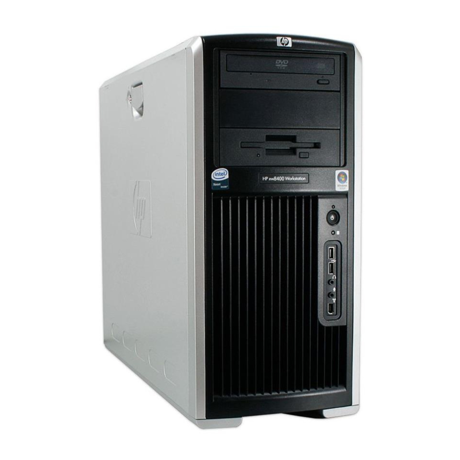
Front panel components The following image shows a typical HP xw9400 Workstation. Drive configurations can vary. Figure 1-2 Front panel components Table 1-2 Front panel components Item Symbol Description Item Symbol Description Optical drive Headphone connector 5.25-inch drive bay USB 2.0 ports... -
Page 12: Rear Panel Components
Rear panel components Figure 1-3 Rear panel components Table 1-3 Rear panel components Item Symbol* Description Item Symbol Description Power cord connector Graphics adapter Built In Self Test (BIST) LED Audio line-in connector Serial connector RJ-45 network connectors SPDIF OUT** IEEE-1394a connector Keyboard connector Mouse connector... -
Page 13: Serial Number And Coa Label Location
Serial number and COA label location Each workstation has two unique serial number labels. Systems preinstalled with Microsoft® Windows® XP also have a certificate of authentication (COA) label (2). The serial number labels (1) are located on the side panel of the unit and on the rear panel. Keep the serial number available when contacting customer service for assistance. -
Page 14: Product Specifications
Product specifications The following table lists the physical dimensions. Table 1-4 Physical characteristics Weight (depending on 18-27.7 kg (39.6-61.1 lb.) configuration) Tower dimensions 455 mm (17.9 in.) tall, 210 mm (8.3 in.) wide, 525 mm (20.7 in.) deep Rack mount dimensions (top 210 mm (8.3 in.) tall, 440 mm (17.3 in.) wide, 525 mm (20.7 cover and foot removed) in.) deep... -
Page 15: Power Supply Specifications
Table 1-6 Current specification (continued) Current Continuous Description 12 V CPU1 16.7 A Input to onboard regulators that supply power for CPU1 and the chipset 12 V-M 18.6 A Input to onboard regulators that supply power for memory 12 V-B 15.7 A Used with PCI, fans, onboard logic, and audio regulators... -
Page 16: Power Consumption And Cooling
Table 1-7 Power supply specifications (continued) FEMP standby power compliant @ 115 V (<2W @ 115 V in S5–Power Off) Power consumption in ES mode <10 W Suspend to RAM (S3) (Instantly Available PC) Power consumption and cooling The following table shows the primary power consumption for an example configuration: ●... -
Page 17: System Fans And Airflow
The length of the cord must be between 6 feet (1.8 m) and 12 feet (3.6 m). If you have questions about the type of power cord to use, contact the HP authorized service provider. -
Page 18: Pci Card Slot Power Specification
Table 1-10 Environmental Specifications (continued) Temperature (non-operating) -40° to 140° F (-40° to 60° C) Humidity (operating) 8% to 85% RH, non-condensing Humidity (non-operating) 8% to 90% RH, non-condensing Maximum Altitude (operating) 0 to 10,000 ft. (3,048 m) Maximum Altitude (non-operating) 0 to 30,000 ft. - Page 19 3, which is the PCI slot below the graphics slot. If a graphics card requiring more than 75W is installed in slot 5, HP recommends not using slot 6, which is the PCI-X 100 slot below the graphics slot. In addition to these slot power specifications, the overall power consumption of the system (including I/O cards, processors, memory, and drives) must not exceed the maximum ratings of the system power supply.
-
Page 20: Chipkill Support
Chipkill is a form of advanced Error Checking and Correcting (ECC) computer memory technology. The HP xw9400 Workstation supports 128-bit Chipkill ECC memory functionality. Standard ECC functionality detects and corrects single bit data errors in memory systems. But Chipkill offers greater memory error protection by providing error correction for up to 4-bit errors within the same symbol (nibble boundary). -
Page 21: Energy Star
HP products purchased with the Energy Star configuration are compliant with U.S. Environmental Protection Agency (EPA) Computers Program. The EPA Energy Star configuration does not imply endorsement by the EPA. As an Energy Star partner, HP offers products with the Energy Star configuration to meet the Energy Star guidelines for energy efficiency. - Page 22 Chapter 1 Product overview ENWW...
-
Page 23: Installing Or Restoring The Operating System
This chapter describes the installation and restoration of the operating system. ● Installing the operating system and software on page 16 ● HP software on page 18 ● Restoring the operating system on page 19 ● Protecting the software on page 22 If your workstation was shipped with a preinstalled operating system, it is configured automatically the first time your workstation is powered on. -
Page 24: Installing The Operating System And Software
After the boot process completes, you can view additional HP Linux documentation by opening your Internet browser (the browser is automatically set to use the local HP documentation page as its default). You can also access Linux Web links for Red Hat (Internet access required) by using your Internet browser. -
Page 25: Linux-Enabled Workstations
Red Hat box set. The Installer kit includes the HP CDs necessary to complete the installation of all versions of the Red Hat box set that have been verified to work on HP workstation hardware. -
Page 26: Hp Software
HP software The following HP software may be installed on your workstation depending on the operating system and options: ● Computer Setup (F10) Utilities and diagnostic features ● HP Support Software including device drivers ● Security Management tools ● Software Support Management tools Additional software is available for download: ●... -
Page 27: Restoring The Operating System
CDs for RestorePlus!, the Windows operating system, and a supplemental HP Backup and Recovery Manager CD. (There may be additional CDs you can create depending on the options you purchased.) You also have the option to move images of the CDs to another location, such as a network share, to be burned to CD at a later time or from another system. -
Page 28: Hp Backup And Recovery Manager Restore Points
Ordering backup software If you are unable to create system recovery CDs or DVDs, the HP Restore Plus CD set can be obtained through product support on http://www.hp.com/support. Chapter 2 Installing or restoring the operating system... -
Page 29: Restoring The Linux Operating System
Reboot your workstation. Follow the prompts to set up your system with the Red Hat First Boot utility. When prompted in First Boot to add additional CDs, insert the HP Driver CD into the CD-ROM tray of your workstation. Click Install next to “Additional CDs.” The HP Driver CD window opens. -
Page 30: Protecting The Software
Protecting the software To protect software from loss or damage, keep a backup copy of all system software, applications, and related files stored on the hard drive. See the operating system or backup utility documentation for instructions on making backup copies of data files. Chapter 2 Installing or restoring the operating system ENWW... -
Page 31: System Management
System management This section describes the various tools and utilities that allow for the system management of the workstation. ● Computer Setup (F10) Utility on page 24 ● Desktop management on page 34 ENWW... -
Page 32: Computer Setup (F10) Utility
Computer Setup (F10) Utility The Computer Setup Utility enables you to: ● Change current settings from the factory default settings. ● Modify or restore factory default settings. ● Determine if all of the devices installed on the workstation are recognized by the system and functioning properly. -
Page 33: Bios Rom
BIOS ROM The BIOS of the computer is a collection of programs stored as firmware in ROM. The BIOS ROM includes such functions as POST, PCI device initialization, Plug 'n' Play support, power management activities, and the Computer Setup Utility. BIOS supports the following systems and specifications: ●... -
Page 34: Computer Setup (F10) Utility Menu
Use the left and right arrow keys to select the appropriate heading. Use the up and down arrow keys to select the option you want, and press Enter. To apply and save changes, select File>Save Changes and Exit. ● If you have made changes that you do not want applied, select File>Ignore Changes and Exit. - Page 35 Table 3-1 Computer Setup Utility menu descriptions (continued) Heading Option Description Storage Device Lists all installed non-SAS and non-SATA storage devices. Configuration When a device is selected, detailed information and options are displayed. CD-ROM Identifies the optical drives on the system. Diskette (for legacy diskette drives only) Identifies the highest capacity media type accepted by the diskette drive.
- Page 36 Table 3-1 Computer Setup Utility menu descriptions (continued) Heading Option Description Storage Removable Media Boot Options Enables/disables ability to boot the system from removable media. Legacy Diskette Write Enables/disables ability to write data to legacy media. BIOS DMA Data Transfers Enables/disables DMA transfers for IDE and SATA devices when possible during POST to increase transfer speed.
- Page 37 Table 3-1 Computer Setup Utility menu descriptions (continued) Heading Option Description Security Setup Enables you to set and enable setup (administrator) password. Password NOTE If the setup password is set, you must enter Computer Setup Utility to change it, flash the ROM, and make changes to certain plug-and-play settings under Windows. Power-On Enables you to set and enable the power-on password.
- Page 38 Table 3-1 Computer Setup Utility menu descriptions (continued) Heading Option Description Advanced Power-On POST Mode (QuickBoot, FullBoot, or FullBoot every 1–30 days) Options Quick boot is faster by skipping some steps such as the full memory test. POST Messages (Enable/Disable). When enabled, POST displays non-error messages to the screen.
- Page 39 Table 3-1 Computer Setup Utility menu descriptions (continued) Heading Option Description When awakening from the ACPI S3 state, reset IDE hard drive before returning to the OS. ACPI S3 PS2 Mouse Wake Up (Enable/Disable) Allow the mouse to awaken the system from the ACPI S3 state. USB Wake on Device Insertion (Enable/Disable) Awaken the system from ACPI S3 state on USB device insertion.
- Page 40 APIC Interrupts APIC Allow manual configuration of system IRQs. For more details on using this feature and on maximizing interrupt performance, refer to the Optimizing APIC Interrupt Assignments on the xw9400 white paper available at http://tclperf.fc.hp.com/performance_briefs/index.htm. Onboard Disable or set IRQ, DMA, and I/O Range values for legacy devices.
- Page 41 Table 3-1 Computer Setup Utility menu descriptions (continued) Heading Option Description For PCI Express slots, the available option is Option ROM Download. For PCI and PCI-X slots, the available options are Option ROM Download and Latency Timer. * Available on select models. ** These options should be used by advanced users only.
-
Page 42: Desktop Management
Desktop management HP Client Management Solutions (available for download from http://www.hp.com/go/easydeploy) provides standards-based solutions for managing and controlling workstations in a networked environment. This section summarizes the capabilities and features of desktop management key components: ● Initial configuration and deployment on page 34 ●... -
Page 43: Managing And Updating Software
Altiris Client Management solutions HP and Altiris have partnered to provide comprehensive, tightly integrated systems management solutions to reduce the cost of owning HP client PCs. HP Client Manager Software is the foundation for additional Altiris Client Management Solutions that address: ●... -
Page 44: System Software Manager
Subscriber’s Choice Subscriber’s Choice is a client-based service from HP. Based on your profile, HP supplies you with personalized product tips, feature articles, and driver and support alerts and notifications. Subscriber’s Choice Driver and Support Alerts/Notifications deliver e-mails notifying you that the information you subscribed to in your profile is available for review and retrieval. -
Page 45: Rom Flash
Remote ROM flash Remote ROM Flash enables you to safely upgrade the ROM on remote HP workstations directly from the centralized network management console. Performing this task remotely on multiple workstations and personal computers results in a consistent deployment of and greater control over HP ROM images over the network. -
Page 46: Replicating The Setup
NOTE Setup configuration procedures require a diskette or a USB such as an HP DriveKey. To collect and replicate BIOS settings on multiple computers, use System Software Manager or HP Client Manager Software. -
Page 47: Copying To A Single Workstation
A setup configuration is model-specific. File system corruption can result if the source and target workstations are not the same model. For example, do not copy the setup configuration from an HP xw6200 Workstation to an HP xw9400 Workstation. Select a setup configuration to copy, then shut down the workstation. -
Page 48: Dual-State Power Button
Worldwide web site HP engineers rigorously test and debug software developed by HP and third-party suppliers, and develop operating system specific support software, to ensure performance, compatibility, and reliability for HP workstations. -
Page 49: Building Blocks And Partners
HP has made the task of locating, accessing, evaluating, and installing the latest support software easier. You can download the software from http://www.hp.com/support. The Web site contains the latest device drivers, utilities, and flashable ROM images needed to run the latest Microsoft Windows operating system on the HP workstation. -
Page 50: Password Security
Table 3-3 Security features overview Feature Purpose How It Is Established Removable Media Boot Control Prevents booting from the removable media Computer Setup Utility Menu. drives. Serial, Parallel, USB, or Infrared Prevents transfer of data through the Computer Setup Utility menu. Interface Control integrated serial or USB interfaces. -
Page 51: Establishing A Setup Password In The Computer Setup (F10) Utility
NOTE System Software Manager and HP Client Manager Software allow remote management of setup passwords and other BIOS settings in a networked environment. For more information, see http://www.hp.com/go/easydeploy. Establishing a setup password in the Computer Setup (F10) Utility Establishing a setup password through the Computer Setup Utility prevents reconfiguration of the workstation (through use of the Computer Setup Utility) until the password is entered. -
Page 52: Entering A Power-On Password
Select Security>Power-On Password, and follow the on-screen instructions. Before exiting, select File>Save Changes and Exit. Entering a power-on password To enter a power-on password: Power on or restart the workstation. When the key icon appears on the monitor, enter the current password, and press Enter. NOTE Type carefully. -
Page 53: Deleting A Power-On Or Setup Password
When the key icon appears, enter the current password, a slash (/) or alternate delimiter character, your new password, another slash (/) or alternate delimiter character, and your new password again as shown: current password/new password/new password NOTE Type carefully. For security reasons, the characters you enter do not appear on the screen. -
Page 54: Clearing Passwords
Table 3-4 National keyboard delimiter characters (continued) Arabic Greek Russian Czech Korean Taiwanese Danish Latin American Thai French Norwegian Turkish French é Polish U.K. English Canadian German Portuguese U.S. English * For Bosnia-Herzegovina, Croatia, Slovenia, and Yugoslavia. Clearing passwords If you forget your password, you cannot access the workstation. See Resetting the password jumper on page 176 for instructions on clearing passwords. -
Page 55: Cable Lock Provision (Optional)
Drive Protection System The Drive Protection System (DPS) is a diagnostic tool built into the hard drives installed in select HP workstations. DPS is designed to help diagnose problems that might result in unwarranted hard drive replacement. -
Page 56: Thermal Sensors
Thermal sensors A thermal sensor is a hardware and software feature that tracks temperature. When combined with HP Client Manager Software, a thermal sensor notifies the network administrator when a normal temperature range is exceeded. For example, a thermal sensor monitors processor temperature. If processor temperature remains too high, the system eventually shuts down. -
Page 57: Removal And Replacement Procedures
Removal and replacement procedures This chapter describes removal and replacement procedures of most internal components. ● Service considerations on page 50 ● Customer Self Repair on page 54 ● Pre-disassembly procedures on page 55 ● System board components on page 56 ●... -
Page 58: Service Considerations
Service considerations The following sections discuss service considerations that should be reviewed and practiced before removing and replacing any system components. WARNING! When lifting or moving the workstation, do not use the front bezel as a handle or lifting point. Lifting the workstation from the front bezel or lifting it incorrectly can cause the unit to fall and harm the user and damage the workstation. -
Page 59: Preventing Electrostatic Damage To Equipment
Preventing electrostatic damage to equipment Many electronic components are sensitive to ESD. Circuitry design and structure determine the degree of sensitivity. The following packaging and grounding precautions are necessary to prevent damage to electric components and accessories. ● Transport products in static-safe containers, such as tubes, bags, or boxes, to avoid hand contact. ●... -
Page 60: Recommended Materials And Equipment
If an incorrect screw is used during the reassembly process, it can damage the unit. HP strongly recommends that all screws removed during disassembly be kept with the removed part and then returned to their proper locations. -
Page 61: Cables And Connectors
Cables and connectors Cables must be handled with care to avoid damage. Apply only the tension required to seat or unseat the cables during insertion or removal from the connector. Handle cables by the connector or pull strap whenever possible. In all cases, avoid bending or twisting the cables, and be sure that the cables are routed in such a way that they cannot be caught or snagged by parts being removed or replaced. -
Page 62: Customer Self Repair
Customer Self Repair Customer Self Repair (CSR) enables you to obtain replacement parts and install them yourself on your workstation. See http://www.hp.com/go/selfrepair/ for more information. Chapter 4 Removal and replacement procedures ENWW... -
Page 63: Pre-Disassembly Procedures
Pre-disassembly procedures After shutdown, perform the following steps before servicing the workstation: Remove or disengage any security devices that prohibit opening the workstation. Close any open software applications. Remove any diskettes or CDs from the workstation. Exit the operating system. Shut down the workstation and any peripheral devices that are connected to it. -
Page 64: System Board Components
System board components The following image shows the system board connectors and sockets on the HP xw9400 Workstation. Figure 4-1 System board identification Table 4-3 System board components Item Description Item Description Item Description Item Description Main power Memory fan... - Page 65 Table 4-3 System board components (continued) Item Description Item Description Item Description Item Description IEEE 1394/USB PCI-X 100/133 Serial ATA (SATA) Battery LAN/USB CD audio Hard disk activity CPU0 Chassis fan Auxiliary audio Password jumper CPU1 fan LAN/USB Front audio Crisis recovery Memory power jumper...
-
Page 66: System Board Architecture
System board architecture The following image shows the HP xw9400 Workstation block diagram. Figure 4-2 System board block diagram Chapter 4 Removal and replacement procedures ENWW... -
Page 67: Removing And Replacing Components
“Setup and Install – General” for instructions. 3. See the manufacturer’s web site for instructions for a third party (non-HP) component. Disassembly order Use the following table to determine the sequence in which to remove the major components. - Page 68 Power button and front speaker (Power button assembly and system speaker on page Optical drive (Optical drive on page Diskette drive (Diskette drive (optional) on page Bezel blanks (Bezel blanks on page Power supply (Power supply on page System fan (System fan on page Memory fan...
-
Page 69: Security Lock (Optional)
Security lock (optional) If a security padlock is installed, remove it before servicing the unit. To remove the padlock, unlock it and slide it out of the padlock loop as shown in the following image. Figure 4-3 Removing the security lock Cable lock (optional) If a cable lock is installed, remove it before servicing the unit. -
Page 70: Front Bezel
WARNING! Before removing the workstation access panel, be sure that the workstation is powered off and that the power cord is disconnected from the electrical outlet. Disconnect power from the system. If a lock is present, unlock the access panel (Access panel on page 61). -
Page 71: Bezel Blanks
Figure 4-6 Opening the front bezel Bezel blanks To remove the bezel blanks: Disconnect power from the system, ( Pre-disassembly procedures on page 55), remove the access panel, and remove the front bezel (Front bezel on page Remove the bezel blanks by squeezing in on the tabs (1) and pulling in the bezel blanks (2). Figure 4-7 Removing the bezel blanks ENWW... -
Page 72: Hood Sensor (Smart Cover Sensor)
Hood sensor (Smart cover sensor) To remove the hood sensor: Disconnect power from the system ( Pre-disassembly procedures on page 55) and remove the access panel (Access panel on page 61). Remove the front bezel. Lay the workstation on its side with the system board facing up. -
Page 73: Power Button Assembly And System Speaker
Pull the bracket away from the front panel I/O device assembly. Figure 4-9 Removing the front panel I/O device assembly Slide the front panel cables through the chassis and out the front of the unit. To replace the front panel I/O device assembly, reverse the previous steps. Power button assembly and system speaker The power button and the system speaker are part of the same assembly. - Page 74 Dislodge the metal clip from the chassis by rocking the power button back and forth. Then slide the power button assembly (2) out from the front of the chassis. Figure 4-10 Removing the power button assembly To remove the speaker: Disconnect the speaker cable from the in-line front panel I/O device assembly cable, if you have not already done so.
-
Page 75: Power Supply
Power supply Disconnect power from the system ( Pre-disassembly procedures on page 55), and remove the access panel (Access panel on page 61). Place the workstation on its side with the system board facing up. Disconnect the three power supply cable connectors from the system board. NOTE Cable ties and cable clips may be present. -
Page 76: Memory Fan
Press down on the ribbed portion of the system fan housing (2), rotate the fan housing down, and lift the unit out of the chassis. Figure 4-13 Removing the system fan To replace the system fan, reverse the previous steps. CAUTION When installing the system fan, be sure that the fan is situated so that the airflow direction is going out of the chassis to avoid overheating. -
Page 77: Memory
Standard ECC PC2-5300 DIMMs ● No support for mirroring ● No spare DIMM support Memory module requirements ● Use only PC2-5300 ECC DIMMs. Certified and warranted HP memory is recommended. ● Match DIMM pairs by size and type. ENWW Removing and replacing components... -
Page 78: Removing Memory Module
Removing memory module Disconnect power from the system ( Pre-disassembly procedures on page 55), and remove the access panel (Access panel on page 61). Place the workstation on its side with the system board facing up. CAUTION To ensure that memory modules are not damaged during removal or installation, power off the workstation and unplug the power cord from the AC power outlet. -
Page 79: Installing A Memory Module
DIMM. Installing a memory module NOTE HP only ships DIMMs that are electrically and thermally compatible with this product. Because third-party DIMMs might not be electrically or thermally compatible, they are not supported by HP. Disconnect power from the system (... - Page 80 Depress the green tabs on the memory fan housing (1) and lift the unit out of the chassis (2). Figure 4-17 Removing the memory fan Gently push out on the socket levers. Prepare to load memory modules in valid configurations: ●...
-
Page 81: Pci Slots
The BIOS generates warnings/errors on invalid memory configurations. ● If BIOS cannot obtain a valid memory configuration, it will halt the system with a diagnostics 2006 code for memory error (five beeps and blinks). ● If memory node interleave is enabled but the memory installed on the two CPUs is not equal, BIOS will report a warning during POST (“215-Cannot Interleave Unequal Memory Nodes”). -
Page 82: Removing The Pci Retainer
Removing the PCI retainer Disconnect power from the system ( Pre-disassembly procedures on page 55), and remove the access panel (Access panel on page 61). Place the workstation on its side with the system board facing up. For both short and tall cards, press in on the sides (1) of the retainer, and rotate it (2) out of the chassis. -
Page 83: Pci Retention Clamp
For both short and tall PCI cards, attach the hooks of the PCI retainer (1) under the slots on the rear of the chassis, and then rotate the retainer down until the retainer arm (2) supports the card. Figure 4-21 Installing the short or tall card PCI retainer PCI retention clamp Disconnect power from the system (... -
Page 84: Removing Pci Or Pci Express Cards
For example, a PCI Express x8 card does not work in a PCI Express x1 slot, but a PCI Express x1 card works in a PCI Express x8 slot. Table 4-5 PCI Express compatibility matrix for xw9400 Slot 1* Slot 2... -
Page 85: Pci Or Pci Express Installation
Lift the PCI card out of the chassis (2). If removing a PCI Express high-end graphics card, remove the auxiliary power supply cable (not illustrated) if required, and move the lever to release the card (3) and lift it out of the chassis. Store the card in an anti-static bag. Figure 4-23 Removing PCI or PCIe card For cards with extenders, release the PCI Express slot latch (1) and lift up slightly. -
Page 86: Front Fan Removal
Remove the PCI slot cover (2). Lower the PCI (3) or PCI Express (3) card into the chassis. Verify that the keyed components of the card align with the socket. If installing a card with an auxiliary power connector, plug in the power supply cable or adapter cable supplied with the card (4). - Page 87 Release the two card guide latches (1), pivot the card guide toward the system board (2), and lift it out of the chassis (3). Figure 4-26 Removing card guide Remove the fan from the card guide by releasing the two latches and applying outward pressure on the card guide while lifting the fan away.
-
Page 88: Battery
Set the front fan in the card guide and snap the fan into place. Figure 4-28 Installing the fan in card guide Lower the card guide with installed fan into the chassis. Place the card guide tabs into the chassis slots and snap the card guide into place. -
Page 89: Power Connections To Drives
Figure 4-29 Removing the battery To install the battery, slide the battery into the holder until it snaps into place. Power connections to drives For help in identifying power cables, refer to the following figure and table. Route or tie cables so that they cannot interfere with the CPU heatsink fans. - Page 90 Figure 4-30 Identifying correct power connections Table 4-6 Power connector descriptions Connector Description 24-pin main power connector 4-pin memory power connector 8-pin processor power connector P4–P8 SATA and IDE ODD/ accessory power connectors Diskette connector P10–P14 HDD connector PCIe connector PCIe connector Chapter 4 Removal and replacement procedures ENWW...
-
Page 91: Optical Drive
Optical drive Your workstation might have a SATA or an IDE optical drive. To remove the optical drive: Disconnect power from the system ( Pre-disassembly procedures on page 55). Remove the access panel (Access panel on page 61) and the front bezel (Front bezel on page 62). -
Page 92: Replacing The Sata Optical Drive Data Cable
To replace an optical drive: Lift the green drivelock release lever while sliding the optical drive into the bay. When the optical drive is partially inserted, release the drivelock release lever, and slide the drive completely into the bay until the drive is secured. CAUTION Ensure that the optical drive is secure. - Page 93 Disconnect the cables from the back of the diskette drive. Figure 4-34 Disconnecting cables from the diskette drive While lifting the green drivelock release tab, slide the drive forward out of the chassis. Figure 4-35 Removing the diskette drive from the chassis ENWW Removing and replacing components...
- Page 94 Remove the diskette drive from its bracket by removing the two M3 screws in the rear-most holes and pulling the diskette drive from the bracket. Figure 4-36 Removing the diskette drive from the bracket To replace a diskette drive: Slide the diskette drive into the bracket, and secure it with two M3 screws. While lifting the green drivelock release tab, slide the drive into the chassis.
-
Page 95: Hard Drive
Hard drive Replacing a hard drive For more information on SATA hard drives and the SATA RAID configuration, see SATA devices on page 145. Removing a hard drive Disconnect power from the system ( Pre-disassembly procedures on page 55), and remove the access panel (Access panel on page 61). -
Page 96: Installing A Hard Drive
Installing a hard drive Select a drive bay in which to install the drive. If installing more than one hard drive, use the hard drive order shown in the following image. Figure 4-39 Identifying hard drive installation order Squeeze the green tabs, and slide the rails out of the empty bay. Attach the rails to the hard drive. - Page 97 Attach a data cable from a SATA connector on the system board to the hard drive, and attach a power cable to the drive. Figure 4-41 Replacing the SATA hard drive For a SAS hard drive, attach a SAS/SATA adapter to the connector on the hard drive. Attach a data cable from a SAS connector on the system board to the hard drive, and attach a power cable to the drive.
-
Page 98: Installing A Hard Drive In The Fifth Hard Drive Bay
Installing a hard drive In the fifth hard drive bay To install a hard drive into fifth HDD bay: Place the workstation on its side, and remove the three drive screws that are located on the bottom of the chassis. Figure 4-43 Installing screws for the hard drive in the fifth hard drive bay Insert the drive into bay 5, and align the holes in the bottom of the hard drive with the screw holes... -
Page 99: Processor Heatsink
Processor heatsink Removing the CPU heatsink NOTE The following illustrated CPU heatsink is typical of what you might have in your workstation. Be aware that different variations of the CPU heatsinks exist, but the overall procedures listed are sufficient to assist you in removing the CPU heatsink. Shut down the workstation, and disconnect power from the system ( Pre-disassembly procedures on page... -
Page 100: Replacing The Cpu Heatsink
Before lifting the heatsink, carefully break the adhesive compound between the CPU heatsink and processor by moving the heatsink back and forth or twisting it (2). Figure 4-46 Removing the CPU heatsink from the system board Use alcohol and a soft cloth to clean all of the thermal interface material residue from the CPU heatsink and processor. - Page 101 Connect the CPU heatsink fan connector to the system board (2). Figure 4-47 Replacing the CPU heatsink on the system board Insert and tighten the two CPU heatsink screws. First, tighten both screws partially so that the CPU heatsink remains level. Next, fully tighten one screw (1), then fully tighten the remaining screw (2).
-
Page 102: Processor
Processor Removing the processor CAUTION Use extreme care when installing or removing a processor. The exposed socket pins are extremely fragile. Damaged sockets will require a board replacement. Lift the processor out of the socket— do not slide the processor on the socket. When installing a processor, align the dimples on the side of the processor with the notches in the socket. - Page 103 Lift the processor straight out of the socket. Figure 4-50 Lift the processor from the socket CAUTION To avoid bending the socket pins, keep the processor perfectly flat when removing or installing it. NOTE Store the processor in a static-free, safe place where it will not be damaged. In some workstation configurations, a bypass board may be installed in the socket instead of a processor.
-
Page 104: Replacing The Processor
Replacing the processor CAUTION Use extreme care when installing or removing a processor. The exposed socket pins are extremely fragile. Damaged sockets will require a board replacement. Lift the processor out of the socket— do not slide the processor on the socket. When installing a processor, align the dimples on the side of the processor with the notches in the socket. -
Page 105: Replacing The System Board
Rotate the system board latch lever 90 degrees (1) clockwise to unlock the system board. Slide the system board forward (2) to disengage the metal mounting standoffs from the chassis. CAUTION Do not attempt to remove the system board mounting screws. These screws are permanently secured and are not removable. - Page 106 Chapter 4 Removal and replacement procedures ENWW...
-
Page 107: System Diagnostics And Troubleshooting
E-Support on page 100 ● Troubleshooting checklist on page 101 ● LED color definitions on page 102 ● HP Insight Diagnostics Offline Edition on page 103 ● Diagnostic error codes on page 107 ● Troubleshooting scenarios and solutions on page 110 ●... -
Page 108: E-Support
To open HSC from your desktop, click Start>Help and Support. HSC contains four sections: ● HP Product Information (requires Internet access)—Links to the HP Technical Support website for your product. You can access all related documentation, downloads and updates, tools, and more. ●... -
Page 109: Troubleshooting Checklist
Troubleshooting checklist Before running any of the diagnostic utilities, use the following checklist to find possible solutions for workstation or software problems. ● Are the workstation and monitor connected to a working electrical outlet? ● Is the workstation powered on? ●... -
Page 110: Led Color Definitions
LED color definitions The front panel LED indicates system status as described in Table 1. Table 5-1 Front panel LED color definitions LED State LED Color System Status Solid Green System is on. Blinking Green System is in Standby mode. Solid or blinking System has an error. -
Page 111: Hp Insight Diagnostics Offline Edition
HP Insight Diagnostics Offline Edition The HP Insight Diagnostics utility enables you to perform testing and to view critical computer hardware and software configuration information from various sources. This utility enables you to: ● Run diagnostics. ● View the hardware configuration of the system. -
Page 112: User Interface
User interface Navigation The Insight Diagnostics home page contains the following tabs: Survey, Test, Status, Log, and Help. These tabs separate the major functions of Insight Diagnostics. Survey tab When you click the Survey tab, the Survey menu displays and enables you to view important system configuration information. -
Page 113: Status Tab
The Status page also shows the: ● Devices being tested ● Tests that are running ● Overall test time ● Individual test times ● Condition status of each test Log tab The Log tab consists of two views: ENWW HP Insight Diagnostics Offline Edition 105... -
Page 114: Help Tab
Exit—Located in the lower-left corner of the display, this selection provides the option to exit diagnostics. Starting the diagnostic utility from CD HP Insight Diagnostics is available on the Documentation & Diagnostic CD that was shipped with your workstation. To start the diagnostic utility on the Documentation & Diagnostic CD: Ensure that the diagnostic CD is inserted in the optical drive. -
Page 115: Diagnostic Error Codes
Diagnostic error codes This sections provides an overview of the diagnostic lights and error codes that are related to your workstation. Diagnostic light codes NOTE The beeps are heard through the chassis speaker. The blinking LEDs and beeps repeat for five cycles. After that, only the blinking LEDs repeat. Table 5-2 Diagnostic LED codes Chassis Indicator LEDs... - Page 116 If fan is plugged in and seated properly, but is not spinning, the problem may be in the processor fan. Contact HP for assistance Verify that the fan assembly is properly attached. If problems persist, there may be a problem with the processor heatsink. Contact HP for assistance. Blinks red/beeps three times, CAUTION...
- Page 117 Clear CMOS by pressing the Clear CMOS button on the system board. Upgrade the ROM using a ROMPaq diskette, CD, diskette, or USB removable device (e.g., HP Drive Key). See the ROM Flash section of the Service and Technical Reference Guide at http://www.hp.com/support/workstation_manuals.
-
Page 118: Troubleshooting Scenarios And Solutions
Troubleshooting scenarios and solutions This section presents an extensive overview of various troubleshooting scenarios and includes possible solutions for each. Solving minor problems Table 5-3 Minor problems Problem Cause Possible Solution Workstation seems to be Program in use has stopped Attempt the normal Windows shut down procedure. -
Page 119: Solving Power Supply Problems
Table 5-3 Minor problems (continued) Problem Cause Possible Solution Replace the processor fan. Reseat CPU heatsink and verify that the fan assembly is properly attached. Workstation does not power on System unable to power on. CAUTION Disconnect AC power from the and the LEDs on the front of workstation before reseating or replacing the workstation are not... - Page 120 To test the power supply: Disconnect AC power to the workstation. Disconnect all internal power supply cables. Plug in AC power. If the green BIST LED on the rear of the workstation is lit and the fan is spinning, the power supply is functional.
-
Page 121: Solving Diskette Problems
Table 5-4 Power supply problems (continued) Problem Cause Solution Replace the processor fan. Reseat the CPU heatsink, and verify that the fan assembly is properly attached. Power LED flashes red, once every Power failure (power supply is CAUTION Disconnect AC power from the two seconds. - Page 122 Table 5-5 Diskette problems (continued) Problem Cause Solution Drive not found. Cable is loose. Reseat diskette drive data and power cables. Removable drive is not seated Reseat the drive. properly. Diskette drive cannot write to a Diskette is not formatted. Format the diskette.
-
Page 123: Solving Hard Drive Problems
Solving hard drive problems Table 5-6 Hard drive problems Problem Cause Solution Hard drive error occurs. Hard disk has bad sectors or Use a disk analysis utility to locate and block usage of bad has failed. sectors. If necessary, reformat the hard disk. Disk transaction problem. -
Page 124: Solving Display Problems
Solving display problems Table 5-7 Display problems Problem Cause Solution Blank screen (no video). The cable connections are not Check the cable connections from the monitor to the correct. workstation and to a working electrical outlet. The monitor is off. Switch the monitor to on (LED is on). - Page 125 Table 5-7 Display problems (continued) Problem Cause Solution Power LED flashes red six times, Pre-video graphics error. CAUTION Disconnect AC power from the once every second, followed by a workstation before reseating or replacing two second pause, and the components because there is power to the system workstation beeps six times.
- Page 126 See the HP Support website and check for an updated unable to center the picture on the interpret the output display driver.
-
Page 127: Solving Audio Problems
Solving audio problems Table 5-8 Audio problems Problem Cause Solution Sound does not come out of the Software volume control is Double-click the Speaker icon on the taskbar and use the speaker or headphones. turned down. volume slider to adjust the volume. The external speakers are not Turn on the external speakers. -
Page 128: Solving Printer Problems
Table 5-8 Audio problems (continued) Problem Cause Solution Sound cuts in and out. Processor resources are being Shut down open processor-intensive applications. used by other open applications. Workstation appears to be locked The hard disk might be full. Before recording, be sure there is enough free space up while recording audio. -
Page 129: Solving Keyboard And Mouse Problems
Solving keyboard and mouse problems Table 5-10 Keyboard and mouse problems Problem Cause Solution Keyboard commands and typing Keyboard connector is not Power off the workstation. are not recognized by the properly connected. Reconnect the keyboard to the workstation and workstation. -
Page 130: Solving Hardware Installation Problems
Some problems in this section are also discussed in other troubleshooting suggestions in this chapter. Table 5-11 Front panel component problems Problem Cause Solution If a USB device, headphone, or It is not properly connected. Power off the workstation. microphone is not recognized by Reconnect the device to the workstation and restart the workstation. - Page 131 Table 5-12 Hardware installation problems Problem Cause Solution A new device is not recognized as Device is not seated or Be sure that the device is properly and securely connected part of the system. connected properly. and that pins in the connector are not bent. Cables of new external device Be sure that all cables are properly and securely connected are loose or power cables are...
-
Page 132: Solving Network Problems
Ensure DIMMs are loaded in the correct slots. Reseat DIMMs. Replace DIMMs one at a time to isolate the faulty module. Replace third-party memory with HP memory. Replace the system board. Power LED flashes red six times, Video card is not seated... - Page 133 Table 5-13 Network problems (continued) Problem Cause Solution Diagnostics reports a failure. The cable is not securely Be sure that both ends of the data cable are securely connected. connected. The cable is attached to the Be sure that the cable is attached to the correct connector. incorrect connector.
-
Page 134: Solving Memory Problems
Unprogrammed EEPROM. Flash the ROM. unprogrammed EEPROM. Solving memory problems CAUTION For those systems that support ECC memory, HP does not support mixing ECC and non-ECC memory. Otherwise, the system will not boot the operating system. Table 5-14 Memory problems Problem... -
Page 135: Solving Processor Problems
Solving processor problems Table 5-15 Processor problems Problem Cause Solution Poor performance is experienced. Processor is hot. Be sure the airflow to the workstation is not blocked. Be sure the fans are connected and working properly (some fans only operate when needed). Be sure the CPU heatsink is installed properly. - Page 136 Table 5-16 CD-ROM and DVD problems (continued) Problem Cause Solution CD-ROM, CD-RW, DVD-ROM, or Disc has been inserted upside Reinsert the disc with the label facing up. DVD-R/RW drive cannot read a down. disc or takes too long to start. The DVD-ROM drive takes Wait at least 30 seconds to let the DVD-ROM drive longer to start because it has to...
-
Page 137: Solving Internet Access Problems
Solving Internet access problems Table 5-17 Internet access problems Problem Cause Solution Unable to connect to the Internet. Internet Service Provider (ISP) Verify Internet settings or contact the ISP for assistance. account is not set up properly. Modem is not set up properly. Reconnect the modem. - Page 138 Table 5-17 Internet access problems (continued) Problem Cause Solution Under Device usage, verify the modem is enabled. If there are further problems, click Troubleshoot and follow the on-screen instructions. 130 Chapter 5 System diagnostics and troubleshooting ENWW...
-
Page 139: Post Error Messages
POST error messages POST is a program run at startup that initializes and runs some tests on installed hardware. An audible and/or visual message occurs if the POST encounters a problem. POST checks the following items to ensure that the workstation system is functioning properly: ●... - Page 140 Verify proper memory module type. Verify 3rd party/HP memory. Try another memory socket. Replace memory module if problem persists. 132 Chapter 5 System diagnostics and troubleshooting...
- Page 141 Table 5-18 POST error messages (continued) Screen Message Probable Cause Recommended Action 211–Memory warning An unknown issue with one of the CAUTION Disconnect AC power from the condition detected DIMMs has been detected. workstation before reseating or replacing components because there is power to the system board even when the workstation is powered down.
- Page 142 Table 5-18 POST error messages (continued) Screen Message Probable Cause Recommended Action 303–Keyboard Controller Error I/O board keyboard controller. CAUTION Disconnect AC power from the workstation before reseating or replacing components because there is power to the system board even when the workstation is powered down.
- Page 143 Table 5-18 POST error messages (continued) Screen Message Probable Cause Recommended Action 516–Processors Do Not Have Installed processors operate at Replace a processor so that both operate at the same the Same Frequency Operating different frequencies. frequency. Range 517–Front IEEE 1394 Not Front IEEE 1394 port is not connected.
- Page 144 Table 5-18 POST error messages (continued) Screen Message Probable Cause Recommended Action 914–Hood Lock Coil is not Hood lock mechanism is missing or Reconnect or replace the hood locking Connected not connected. mechanism. Reseat or replace the hood locking mechanism cable.
- Page 145 Determine if hard drive is giving correct error message. Run the Drive Protection System test if applicable. Apply firmware patch if applicable (see http://www.hp.com/support). Back up contents and replace hard drive. 1800–Temperature Alert Internal temperature exceeds CAUTION Disconnect AC power from the specification.
- Page 146 Table 5-18 POST error messages (continued) Screen Message Probable Cause Recommended Action 1802–CPU0 Not Supported The system board does not support CAUTION Disconnect AC power from the the processor. workstation before reseating or replacing components because there is power to the system board even when the workstation is powered down.
-
Page 147: Appendix A Sas Devices
SAS devices ENWW... -
Page 148: Supported Sas Raid Configurations
Supported SAS RAID configurations The following RAID configurations are supported on the HP xw9400 Workstation. NOTE This section does not apply to configuring RAID in the Linux environment. For RAID in the Linux environment, configure SW RAID configurations as provided by Red Hat Enterprise Linux. -
Page 149: Sas Raid 0 (Is) Configuration
NOTE An xw9400 chassis supports up to 5 internal hard disk drives. Using external cables, up to three additional drives can be connected via individual external drives for a total of eight drives. Up to 128 devices can be supported via connection to a JBOD. -
Page 150: Sas Raid 1 (Im) Configuration
SAS RAID 1 (IM) configuration Follow the steps below to configure an Integrated Mirroring (IM) volume with the BIOS-based configuration utility. The configuration procedure assumes that the system already has the required disks attached to the SAS/SATA ports. At the BIOS splash screen, press any key to view option ROM messages. Press Ctrl-C at the Press Ctrl-C to Start LSI Logic Configuration Utility prompt to enter the... -
Page 151: Sas Raid 1E (Ime) Configuration
SAS RAID 1E (IME) configuration Follow the steps below to configure an Integrated Mirroring Extended (IME) volume with the BIOS-based configuration utility. The configuration procedure assumes that the system already has the required disks attached to the SAS/SATA ports. At the BIOS splash screen, press any key to view option ROM messages. Press Ctrl-C at the Press Ctrl-C to Start LSI Logic Configuration Utility prompt to enter the... -
Page 152: Changing Boot Order
Changing boot order If the RAID array will be a data array, the disk drive with the operating system must appear higher in the boot order. If the RAID array will be the operating system drive, it should appear higher in the boot order. To change the boot order: Press to call up the BIOS Setup utility when booting the system. -
Page 153: Appendix B Sata Devices
SATA devices This appendix describes how to use the NVIDIA MediaShield utility to set up and manage SATA RAID volumes. The SATA RAID option must be enabled in BIOS and the SATA drives must be attached to the workstation ports to configure them into a RAID array. Attach the required number of SATA HDDs for the desired RAID level: ●... -
Page 154: Enable Sata Raid Option In Bios
Enable SATA RAID option in BIOS To enable the SATA RAID option in BIOS: During boot up, press to enter the Setup menu. Entering BIOS Setup (Press F10) appears at the bottom of the screen. If first boot, select the desired language and press Enter. Use the arrow keys to highlight I/O>Device Options and press Enter. -
Page 155: Configuring A Sata Raid Array
Configuring a SATA RAID array To configure a SATA RAID array: At the BIOS splash screen, press any key to view option ROM messages. Press to enter the RAID setup utility when Press F6 to enter RAID setup utility is displayed. On the Define a New Array screen, RAID Mode is highlighted in blue and mirroring is set as the default setting. -
Page 156: Changing Boot Order
Changing boot order If the RAID array will be a data array, the disk drive with the operating system must appear higher in the boot order. If the RAID array will be the operating system drive, it should appear higher in the boot order. To change the boot order: Press to call up the BIOS Setup utility when booting the system. -
Page 157: Deleting Raid Volumes
Deleting RAID volumes Use the NVIDIA MediaShield utility to delete RAID volumes. Press to enter the RAID setup utility when Press F6 to enter RAID setup utility is displayed. The MediaShield Utility displays the array list. One of the arrays listed is highlighted in red. Use the up/down arrow keys to highlight RAID volume to be deleted. - Page 158 150 Appendix B SATA devices ENWW...
-
Page 159: Appendix C Connector Pins
Connector pins ENWW... -
Page 160: Connector Pin Descriptions
Connector pin descriptions Ethernet connector Signal (+) Transmit Data (-) Transmit Data (+) Receive Data Unused Unused (-) Receive Data Unused Unused Serial connector Signal Carrier Detect Receive Data Transmit Data Data Terminal Ready Signal Ground Data Set Ready Request to Send Clear to Send Ring Indicator USB connector... - Page 161 power tpb- tpb+ tpa- tpa+ Microphone connector (1/8 inch) Signal 1 (Tip) Audio 2 (Ring) Power 3 (Shield) Ground Headphone connector (1/8 inch) Signal 1 (Tip) Audio_Left 2 (Ring) Audio_Right 3 (Shield) Ground Line-in audio connector (1/8 inch) Signal 1 (Tip) Audio_In_Left 2 (Ring) Audio_In_Right...
- Page 162 SPDIF OUT internal header Signal +VDC Ground NOTE The SPDIF Out internal header is used in parallel with the SPDIF OUT connector. Only one should be used at a time. SATA connector Signal Signal Signal Data Cable Power Cable Power Cable Ground 3.3-V power 5-V power...
- Page 163 SAS connector Segment Backplane receptacle Plug and cable receptacles Primary signal segment SIGNAL GROUND SIGNAL GROUND SIGNAL GROUND Secondary signal segment SIGNAL GROUND SIGNAL GROUND SIGNAL GROUND Power segment precharge GROUND GROUND GROUND precharge GROUND READY LED GROUND precharge ENWW Connector pin descriptions 155...
- Page 164 VGA cconnector Signal Signal Signal Red Analog Monitor ID Green Analog DDC Serial Data Blue Analog Horizontal Sync Monitor ID +5V DC Vertical Sync DDC Serial Clock DVI connector Signal Signal T.M.D.S DATA 2- HOT PLUG DETECT T.M.D.S DATA 2+ T.M.D.S DATA 0- T.M.D.S DATA 2/4 SHIELD T.M.D.S DATA 0+...
- Page 165 ATA/ATAPI (IDE) standard drive cable connector Signal Signal Signal Reset DMAK DD14 INTRQ DD15 IOCS16 (Key) PDIAG (cable detect) DMARQ DD10 DIOW CS1FX DD11 CS3FX DIOR DASP IORDY CSEL 24-Pin Main power connector +3.3 V -12 V +5 V +3.3 V +5 Vaux +5 V/+5 V-Rsense +12V-B...
- Page 166 4-Pin power (memory system board) connector Color Signal BLK w/YEL stripe +12V-M BLK w/YEL stripe +12V-M 8-Pin power (for CPUs and onboard regulators) Color Signal connector Gray +12 V CPU0 Rsense BLK w/WHT stripe +12 V CPU0 BLK w/WHT stripe +12VCPU0 BLK w/light blue +12VCPU1...
- Page 167 Keyboard connector Signal Data Unused Ground +5 VDC Clock Unused Mouse connector Signal Data Unused Ground +5 VDC Clock Unused ENWW Connector pin descriptions 159...
- Page 168 160 Appendix C Connector pins ENWW...
-
Page 169: D System Board Designators
System board designators This appendix lists the system board designators for this system. Designator Silkscreen Component BAT1 BAT1 Battery retainer CRISIS RECOVERY Boot Block recovery jumper CLR PSWD Clear password jumper None Stacked RJ45/dual USB FRNT 1394 Front panel 1394a header SPDIF OUT connector None Stacked RJ45/dual USB... -
Page 170: Appendix D System Board Designators
Designator Silkscreen Component CD analog audio connector CHASSIS FAN Primary chassis fan header FLPY Floppy connector Auxiliary audio connector SPDIF OUT SPDIF OUT header PRIMARY IDE Primary IDE connector FRNT AUD Front panel audio header FRNTUSB2–3 Front panel USB header IUSB1 Internal USB header IUSB0... - Page 171 * With the jumper on pins 1 and 2, the PCI-X bus speed is 100 MHz, regardless of the card configuration in slots 6 and 7. With the jumper on pins 2 and 3 (default), the following PCI-X bus speed/card configuration applies: Card configuration Max PCI-X bus speed achieved*...
- Page 172 164 Appendix D System board designators ENWW...
-
Page 173: Appendix E Power Cord Set Requirements
The length of the cord must be between 1.8 m (6 feet) and 3.6 m (12 feet). If you have questions about the type of power cord to use, contact an HP authorized service provider. - Page 174 166 Appendix E Power cord set requirements ENWW...
-
Page 175: Appendix F Routine Care
Routine care ENWW... -
Page 176: General Cleaning Safety Precautions
General cleaning safety precautions ● Never use solvents or flammable solutions to clean the workstation. ● Never immerse any component in water or cleaning solutions; apply any liquids to a clean cloth and then use the cloth on the component. ●... -
Page 177: Maximizing The Airflow
Maximizing the airflow ● Keep your workstation in an area where the airflow to the front and rear of the system is not obstructed. ● If possible, keep the unit off of surfaces where dust can gather. ● Keep the back of the unit at least 0.15 m (6 in.) away from a wall or other obstruction. ●... -
Page 178: Cleaning The Workstation Case
Cleaning the workstation case ● Follow the safety precautions presented in Service considerations on page 50 before cleaning the workstation. ● To remove light stains or dirt, use plain water with a clean, lint-free cloth or swab. ● For stronger stains, use a mild dish-washing liquid diluted with water. Rinse well by wiping it with a cloth or swab dampened with clear water. -
Page 179: Cleaning The Keyboard
Cleaning the keyboard CAUTION Use safety glasses equipped with side shields before attempting to clean debris from under the keys. ● Follow the safety precautions presented in Service considerations on page 50 before cleaning the keyboard. ● Visible debris underneath or between the keys can be removed by vacuuming or shaking. ●... -
Page 180: Cleaning The Monitor
Cleaning the monitor ● Follow the safety precautions presented in Service considerations on page 50 before cleaning the monitor. ● To clean the monitor, wipe the monitor screen with a towelette designed for cleaning monitors or a clean cloth moistened with water. CAUTION Do not use sprays or aerosols directly on the screen—the liquid might seep into the housing and damage a component. -
Page 181: Cleaning The Mouse
Cleaning the mouse Follow the safety precautions presented in Service considerations on page 50 before cleaning the mouse. Remove the mouse ball from the housing by removing the retaining plate. Clean the mouse ball. Pull out any debris from the ball socket, and wipe the ball with a clean, dry cloth. Reassemble the mouse. - Page 182 174 Appendix F Routine care ENWW...
-
Page 183: Appendix G Additional Password Security And Resetting Cmos
Additional password security and resetting CMOS This workstation supports the following security password features, which can be established through the Computer Setup Utility menu: ● Setup password ● Power-on password If only a power-on password is established, it must be entered to boot the workstation. If only a setup password is established, it must be entered to access the setup menu. -
Page 184: Resetting The Password Jumper
Resetting the password jumper To disable the power-on or setup password features and clear the power-on and setup passwords: Shut down the operating system, and power off the workstation and any external devices. Disconnect the power cord of the workstation and any external devices from the power outlets. WARNING! To reduce the risk of personal injury from electrical shock and hot surfaces, be sure to disconnect the power cord from the wall outlet and allow the internal system... -
Page 185: Clearing And Resetting The Cmos
Clearing and resetting the CMOS The CMOS of the workstation stores password information and information about the workstation configuration. This section describes the steps to successfully clear and reset the CMOS. Using the CMOS button Shut down the operating system, and power off the workstation and any external devices. Disconnect the power cord of the workstation and any external devices from the power outlets. -
Page 186: Using The Computer Setup Utility To Reset Cmos
Using the Computer Setup Utility to reset CMOS To reset CMOS to factory defaults: Enter the Computer Setup Utility menu by pressing when the F10=Setup prompt displays on the screen during bootup. The word Setup displays in the lower right corner of the screen. If a setup password has been set, a password prompt displays on the screen. - Page 187 Quick troubleshooting flowcharts This appendix presents some quick troubleshooting flowcharts for the following issues: ● Initial troubleshooting ● No power ● No video ● Error messages ● No OS loading ● No OS loading from hard drive ● No OS loading from diskette drive ●...
-
Page 188: Initial Troubleshooting
Initial troubleshooting 180 Appendix H Quick troubleshooting flowcharts ENWW... -
Page 189: No Power
No power No power, part 1 ENWW No power 181... -
Page 190: No Power, Part 2
No power, part 2 182 Appendix H Quick troubleshooting flowcharts ENWW... - Page 191 No power, part 3 ENWW No power 183...
-
Page 192: No Video
No video No video, part 1 184 Appendix H Quick troubleshooting flowcharts ENWW... -
Page 193: No Video, Part 2
No video, part 2 ENWW No video 185... - Page 194 No video, part 3 186 Appendix H Quick troubleshooting flowcharts ENWW...
-
Page 195: Error Messages
Error messages Error messages, part 1 ENWW Error messages 187... -
Page 196: Error Messages, Part 2
Error messages, part 2 188 Appendix H Quick troubleshooting flowcharts ENWW... - Page 197 Error messages, part 3 ENWW Error messages 189...
-
Page 198: No Operating System Loading
No operating system loading 190 Appendix H Quick troubleshooting flowcharts ENWW... -
Page 199: No Operating System Loading From Hard Drive
No operating system loading from hard drive No operating loading from hard drive, part 1 ENWW No operating system loading from hard drive 191... -
Page 200: No Operating System Loading From Hard Drive, Part 2
No operating system loading from hard drive, part 2 192 Appendix H Quick troubleshooting flowcharts ENWW... - Page 201 No operating system loading from hard drive, part 3 ENWW No operating system loading from hard drive 193...
-
Page 202: No Operating System Loading From Diskette Drive
No operating system loading from diskette drive 194 Appendix H Quick troubleshooting flowcharts ENWW... -
Page 203: No Operating System Loading From Optical Drive
No operating system loading from optical drive ENWW No operating system loading from optical drive 195... -
Page 204: No Operating System Loading From Network
No operating system loading from network 196 Appendix H Quick troubleshooting flowcharts ENWW... -
Page 205: Non-Functioning Device
Non-functioning device ENWW Non-functioning device 197... - Page 206 198 Appendix H Quick troubleshooting flowcharts ENWW...
-
Page 207: Appendix I Pci Bus Layout
PCI bus layout ENWW... -
Page 208: Pci Bus Layout And Device List
PCI bus layout and device list The following illustration shows the HP xw9400 Workstation PCI bus layout. It is followed by a PCI device list description. Figure I-1 PCI bus layout Table I-1 PCI device list Device Bus# Dev# MCP55ProPro HT Config... - Page 209 Table I-1 PCI device list (continued) Device Bus# Dev# MCP55Pro SMBUS MCP55Pro Trim MCP55Pro ASF SMU MCP55Pro USB OHCI MCP55Pro USB EHCI MCP55Pro IDE MCP55Pro SATA0 MCP55Pro SATA1 MCP55Pro SATA2 MCP55Pro P2P Bridge (Bridge to Slot 3) MCP55Pro High Definition Audio Controller MCP55Pro LOM 0 MCP55Pro LOM 1 MCP55Pro PCIE Root Port 0 (Port to Slot 2)
- Page 210 202 Appendix I PCI bus layout ENWW...