Table of Contents
Advertisement
GA-K8VT800(Pro)
AMD Socket 754 Processor Motherboard
User's Manual
Rev. 1005
12ME-K8VT800P-1005
Copyright
© 2005 GIGABYTE TECHNOLOGY CO., LTD
Copyright by GIGA-BYTE TECHNOLOGY CO., LTD. ("GBT"). No part of this manual may be reproduced or transmitted in any from
without the expressed, written permission of GBT.
Trademarks
Third-party brands and names are the property of their respective owners.
Notice
Please do not remove any labels on motherboard, this may void the warranty of this motherboard.
Due to rapid change in technology, some of the specifications might be out of date before publication of this booklet.
The author assumes no responsibility for any errors or omissions that may appear in this document nor does the author make a
commitment to update the information ontained herein.
Advertisement
Table of Contents

Related Manuals for Gigabyte GA-K8VT800


Summary of Contents for Gigabyte GA-K8VT800
- Page 1 User's Manual Rev. 1005 12ME-K8VT800P-1005 Copyright © 2005 GIGABYTE TECHNOLOGY CO., LTD Copyright by GIGA-BYTE TECHNOLOGY CO., LTD. ("GBT"). No part of this manual may be reproduced or transmitted in any from without the expressed, written permission of GBT. Trademarks Third-party brands and names are the property of their respective owners.
- Page 2 Mother Board GA-K8VT800 / GA-K8VT800 Pro September 2, 2003...
- Page 3 Motherboard GA-K8VT800 / GA-K8VT800 Pro September 2 ,2003...
-
Page 4: Read Me First
If your AGP card has "AGP 4X/8X(1.5V) notch" (show below), please make sure your AGP card is AGP 4X/8X(1.5V). AGP 4X/8X notch AGP 2X(3.3V) card is not supported by VIA K8T800 chipset. You might experience system unable to boot up normally. Please insert an AGP 4X/8X(1.5V) card. GA-K8VT800(Pro) Motherboard - 4 -... - Page 5 Preparing Your Computer Computer motherboards and expansion cards contain very delicate Integrated Circuit (IC) chips. To protect them against damage from static electricity, you should follow some precautions whenever you work on your computer. 1. Unplug your computer when working on the inside. 2.
-
Page 6: Table Of Contents
Chapter 1 Introduction ................8 1-1 Item Check List ................8 1-2 Features Summary ................8 1-3 GA-K8VT800(Pro) Motherboard Layout ..........11 1-4 Block Diagram - GA-K8VT800(Pro)............ 12 Chapter 2 Hardware Installation Process ..........15 Step 1: Installing Processor and CPU Cooling Fan ........16 Step 2: Installing Memory Modules ............ - Page 7 Frequency/Voltage Control ................ 58 Load Fail-Safe Defaults ................60 Load Optimized Defaults ................61 Set Supervisor/User Password ..............62 Save & Exit Setup ..................63 Exit Without Saving ................... 64 Chapter 4 Technical Reference ............67 @BIOS Introduction ................. 67 ™...
-
Page 8: Chapter 1 Introduction
The GA-K8VT800(Pro) motherboard Serial ATA cable x 2 CD for motherboard driver & utility USB & IEEE 1394 Cable x 1 The GA-K8VT800(Pro) user's manual USB Cable x 1 Quick PC Installation Guide SPDIF Out Kit x 1 GigaRAID manual... - Page 9 '*' If you want to find the detailed information for SATA RAID setup installation, please download the VT8237 SATA Manual from GIGABYTE’s website. (Note) It is recommended to use SATA (1.5Gb/s) hard disks. For GA-K8VT800 Pro only...
- Page 10 CPU, chipset and most of the peripherals. Whether your system can run under these specific bus frequencies properly will depend on your hardware configurations, including CPU, Chipsets, SDRAM, Cards…etc. For GA-K8VT800 Pro only GA-K8VT800(Pro) Motherboard - 10 -...
-
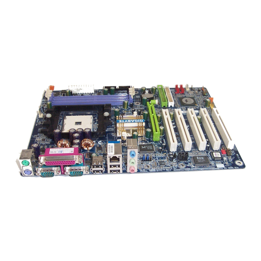
Page 11: 1-3 Ga-K8Vt800(Pro) Motherboard Layout
1-3 GA-K8VT800(Pro) Motherboard Layout CPU_FAN RAM_LED KB_MS SOCKET 754 ATX_12V NB_FAN VIA K8T800 AUDIO PWR_FAN CODEC SATA1 PCI1 SATA0 VIA VT8237 SYS_FAN AUX_IN CD_IN PCI2 CLR_PWD INFO_LINK GigaRAID PCI3 ITE8705 IT8212 TSB43AB23 PCI4 IDE4 BACKUP BIOS IDE3 MAIN PCI5 BIOS... -
Page 12: Block Diagram - Ga-K8Vt800(Pro)
1-4 Block Diagram - GA-K8VT800(Pro) AGP slot CPUCLK+/- (200MHz) 4X/8X Althlon AGPCLK processor (K8) (66MHz) System Bus DDR400/333/266 DIMM 800MHz DDR RAM K8T800 AGPCLK66MHz 3 IEEE1394 5 PCI RJ45 33 MHz 14.318 MHz 48 MHz RTL8110S TSB43AB23 RTL8100C (2 ) - Page 13 - 13 - Introduction...
- Page 14 GA-K8VT800(Pro) Motherboard - 14 -...
-
Page 15: Chapter 2 Hardware Installation Process
Chapter 2 Hardware Installation Process To set up your computer, you must complete the following steps: Step 1- Installing Processor and CPU Cooling Fan Step 2- Installing Memory Modules Step 3- Installing Expansion Cards Step 4- Connect ribbon Cables, Cabinet Wires, And Power Supply Step 4 Step 1 Step 2... -
Page 16: Step 1: Installing Processor And Cpu Cooling Fan
90- degree when a noise “cough” made. Figure 3. A1 pin location on the Socket and Processor.Move the socket lever to the locked position while holding pressure on the center of the processor. GA-K8VT800(Pro) Motherboard - 16 -... - Page 17 Step1-2. When the processor is installed in the socket, apply thermal grease to the processor(as shown in Figure 4) prior to installing the heatsink. AMD recommends using a high thermal conductivity grease (such as Shin-Etsu types G751 or G749, or an equivalent product) for the thermal interface material rather than a phase change material.
-
Page 18: Step 2: Installing Memory Modules
DIMM socket. Then push it down. Fig.2 Close the plastic clip at both edges of the DIMM sockets to lock the DIMM module. Reverse the installation steps when you wish to remove the DIMM module. GA-K8VT800(Pro) Motherboard - 18 -... - Page 19 DDR Introduction Established on the existing SDRAM infrastructure, DDR (Double Data Rate) memory is a high performance and cost-effective solution that allows easy adoption for memory vendors, OEMs, and system integrators. DDR memory is a great evolutionary solution for the PC industry that builds on the existing SDRAM architecture, yet make the awesome advances in solving the system performance bottleneck by doubling the memory bandwidth.
-
Page 20: Step 3: Installing Expansion Cards
/ uninstall the AGP card. Please align the AGP card to the onboard AGP slot and press firmly down on the slot. Make sure your AGP card is locked by the small white- drawable bar. GA-K8VT800(Pro) Motherboard - 20 -... -
Page 21: Step 4: Connect Ribbon Cables, Cabinet Wires And Power Supply
Step 4: Connect ribbon Cables, Cabinet Wires And Power Supply Step 4-1: I/O Back Panel Introduction PS/2 Keyboard and PS/2 Mouse Connector PS/2 Mouse Connector This connector supports standard PS/2 (6 pin Female) keyboard and PS/2 mouse. PS/2 Keyboard Connector (6 pin Female) Before you connect your device(s) into USB USB/LAN Connector... - Page 22 Connect "Center and Subwoofer" to "MIC Out ". Method2: You can refer to page 32, and contact your nearest dealer for optional SUR_CEN cable. If you want the detail information for 2-/4-/6-channel audio setup installation, please refer to page 79. GA-K8VT800(Pro) Motherboard - 22 -...
-
Page 23: Step 4-2: Connectors Introduction
8) IDE1 / IDE2 21) F1_1394 / F2_1394 9) IDE3 / IDE4 22) IR 10) SATA0 / SATA1 23) GAME 11) F_PANEL 24) INFO_LINK 12) BAT 25) CLR_PWD 13) PWR_LED For GA-K8VT800 Pro only - 23 - Hardware Installation Process... - Page 24 AC power cord should only be connected to your power supply unit after ATX power cable and other related devices are firmly connected to the mainboard. Pin No. Definition 3.3V 3.3V Power Good 5V SB (stand by +5V) +12V 3.3V -12V PS_ON(soft on/off) GA-K8VT800(Pro) Motherboard - 24 -...
- Page 25 3) CPU_FAN (CPU Fan Connector) Please note, a proper installation of the CPU cooler is essential to prevent the CPU from running under abnormal condition or damaged by overheating. The CPU fan connector supports Max. current up to 600 mA. Pin No.
- Page 26 (1 1 1 1 1 ) If you installed wrong direction, the chip fan will not work. Sometimes will damage the chip fan. (Usually black cable is GND) Pin No. Definition For GA-K8VT800 Pro only GA-K8VT800(Pro) Motherboard - 26 -...
- Page 27 7) FDD (Floppy Connector) Please connect the floppy drive ribbon cables to FDD. It supports 360K, 1.2M, 720K, 1.44M and 2.88M bytes floppy disk types. The red stripe of the ribbon cable must be the same side with the Pin1. 8) IDE1 / IDE2 (IDE1 / IDE2 Connector) Important Notice: Please connect first hard disk to IDE1 and connect CD-ROM to IDE2.
- Page 28 You can connect the Serial ATA device to this connector, it provides you high speed transfer rates (150MB/sec).If you wish to use SATA0 and SATA1, please Enable " OnChip Serial ATA " item. Then, install the correct driver to have proper operation. For details, please refer to the VT8237 SATA Manual at GIGABYTE's website. SATA1 SATA0 Pin No.
-
Page 29: F_Panel
11) F_PANEL (2 x 10 pins Connector) Please connect the power LED, PC speaker, reset switch and power switch etc. of your chassis front panel to the F_PANEL connector according to the pin assignment above. Speaker Connector Message LED/ Power/ Soft Power Sleep LED Connector... - Page 30 PWR_LED is connect with the system power indicator to indicate whether the system is on/off. It will blink when the system enters suspend mode. If you use dual color LED, power LED will turn to another color. Pin No. Definition MPD+ MPD- MPD- GA-K8VT800(Pro) Motherboard - 30 -...
- Page 31 14) RAM_LED Do not remove memory modules while RAM_LED is on. It might cause short or other unexpected damages due to the stand by voltage. Remove memory modules only when AC power cord is disconnected. 15) F_AUDIO (Front Audio Connector) If you want to use Front Audio connector, you must remove 5-6, 9-10 Jumper.
- Page 32 SPDIF_IO cable, incorrect connection between the cable and connector will make the device unable to work or even damage it. For optional SPDIF_IO cable, please contact your local dealer. Pin No. Definition No Pin SPDIF SPDIFI GA-K8VT800(Pro) Motherboard - 32 -...
- Page 33 18) CD_IN (CD In Connector) Connect CD-ROM or DVD-ROM audio out to the connector. Pin No. Definition CD-L CD-R 19) AUX_IN (AUX In Connector) Connect other device (such as PCI TV Tunner audio out) to the connector. Pin No. Definition AUX-L AUX-R - 33 -...
- Page 34 IEEE1394 cable, please contact your local dealer. F1_1394 F2_1394 Pin No. Definition Power Power Pin No. Definition TPA0+ TPA2+ TPA0- TPA2- TPB0+ TPB0- TPB2+ Power TPB2- Power Power TPA1+ TPA1- Power No Pin No Pin TPB1+ TPB1- GA-K8VT800(Pro) Motherboard - 34 -...
- Page 35 22) IR Be careful with the polarity of the IR connectorwhile you connect the IR. Please contact you nearest dealer for optional IR device. Check the pin assignment carefully while you connect the IR cable, incorrect connection between the cable and connector will make the device unable to work or even damage it.
- Page 36 When Jumper is set to "open" and system is restarted, the password that is set will be cleared. On the contrary when Jumper is set to "close", the current status remains. Open: Clear Password Close: Normal GA-K8VT800(Pro) Motherboard - 36 -...
- Page 37 - 37 - Hardware Installation Process...
- Page 38 GA-K8VT800(Pro) Motherboard - 38 -...
-
Page 39: Chapter 3 Bios Setup
Load the file-safe default CMOS value from BIOS default table <F7> Load the Optimized Defaults <F8> Dual BIOS /Q-Flash function <F9> System Information <F10> Save all the CMOS changes, only for Main Menu For GA-K8VT800 Pro only - 39 - BIOS Setup... -
Page 40: Getting Help
Standard CMOS Features This setup page includes all the items in standard compatible BIOS. Advanced BIOS Features This setup page includes all the items of Award special enhanced features. For GA-K8VT800 Pro only GA-K8VT800(Pro) Motherboard - 40 -... -
Page 41: Integrated Peripherals
Integrated Peripherals This setup page includes all onboard peripherals. Power Management Setup This setup page includes all the items of Green function features. PnP/PCI Configurations This setup page includes all the configurations of PCI & PnP ISA resources. PC Health Status This setup page is the System auto detect Temperature, voltage, fan, speed. -
Page 42: Standard Cmos Features
The week, from Sun to Sat, determined by the BIOS and is display only Month The month, Jan. Through Dec. The day, from 1 to 31 (or the maximum allowed in the month) Year The year, from 1999 through 2098 GA-K8VT800(Pro) Motherboard - 42 -... - Page 43 Time The times format in <hour> <minute> <second>. The time is calculated base on the 24-hour military- time clock. For example, 1 p.m. is 13:00:00. IDE Primary Master, Slave / IDE Secondary Master, Slave The category identifies the types of hard disk from drive C to F that has been installed in the computer. There are two types: auto type, and manual type.
- Page 44 640 K for systems with 640 K or more memory installed on the motherboard. Extended Memory The BIOS determines how much extended memory is present during the POST.This is the amount of memory located above 1 MB in the CPU’s memory address map. GA-K8VT800(Pro) Motherboard - 44 -...
-
Page 45: Advanced Bios Features
Advanced BIOS Features CMOS Setup Utility-Copyright (C) 1984-2003 Award Software Advanced BIOS Features First Boot Device [Floppy] Item Help Second Boot Device [HDD-0] Menu Level Third Boot Device [CD-ROM] Select Boot Device xSATA/RAID/SCSI Boot Order SCSI priority Password Check [Setup] [Floppy] Boot from floppy [LS120]... - Page 46 The system will not boot and will not access to Setup page if the correct password is not entered at the prompt. Setup The system will boot but will not access to Setup page if the correct password is not entered at the prompt. (Default value) GA-K8VT800(Pro) Motherboard - 46 -...
-
Page 47: Integrated Peripherals
[SPP] Game Port Address [201] Midi Port Address [330] Midi Port IRQ [10] : Move Enter:Select +/-/PU/PD:Value F10:Save ESC:Exit F1:General Help F5:Previous Values F6:Fail-Safe Defaults F7:Optimized Defaults Figure 4: Integrated Peripherals For GA-K8VT800 Pro only - 47 - BIOS Setup... -
Page 48: Onchip Serial Ata
Enable VT8237 Serial ATA support. (Default value) Disabled Disable VT8237 Serial ATA support. '* ' If you want find the detailed information for SATA RAID setup installation, please download the VT8237 SATA Manual at GIGABYTE's website AC97 Audio Enabled Enable onboard AC'97 audio function. (Default Value) Disabled Disable this function. -
Page 49: Onboard Fdc Controller
Enable onboard Serial port 1 and address is 2F8. 3E8/IRQ4 Enable onboard Serial port 1 and address is 3E8. 2E8/IRQ3 Enable onboard Serial port 1 and address is 2E8. Disabled Disable onboard Serial port 1. For GA-K8VT800 Pro only - 49 - BIOS Setup... -
Page 50: Onboard Serial Port 2
Parallel Port Mode Using Parallel port as Standard Parallel Port. (Default Value) Using Parallel port as Enhanced Parallel Port. Using Parallel port as Extended Capabilities Port. ECP+EPP Using Parallel port as ECP & EPP mode. GA-K8VT800(Pro) Motherboard - 50 -... - Page 51 Game Port Address Set Game Port Address to 201. (Default Value) Set Game Port Address to 209. Disabled Disable this function. Midi Port Address Set Midi Port Address to 300. Set Midi Port Address to 330.(Default Value) Disabled Disable this function. Midi Port IRQ Set Midi Port IRQ to 5.
-
Page 52: Power Management Setup
Enabled USB Device Wake-Up from S3. Soft-Off by PWRBTN Instant-off Press power button then Power off instantly. (Default value) Delay 4 Sec. Press power button 4 sec to Power off. Enter suspend if button is pressed less than 4 sec. GA-K8VT800(Pro) Motherboard - 52 -... - Page 53 AC BACK Function Memory System power on depends on the status before AC lost. Soft-Off Always in Off state when AC back. (Default value) Full-On Always power on the system when AC back. Keyboard Power On Password Enter from 1 to 5 characters to set the Keyboard Power On Password. Disabled Disabled this function.
-
Page 54: Resume By Alarm
Enable alarm function to POWER ON system. If RTC Alarm Lead To Power On is Enabled. Date ( of Month) Alarm : Everyday, 1~31 Time ( hh: mm: ss) Alarm : (0~23) : (0~59) : (0~59) GA-K8VT800(Pro) Motherboard - 54 -... -
Page 55: Pnp/Pci Configurations
PnP/PCI Configurations CMOS Setup Utility-Copyright (C) 1984-2003 Award Software PnP/PCI Configurations PCI 1/PCI 5 IRQ Assignment [Auto] Item Help PCI 2 IRQ Assignment [Auto] Menu Level PCI 3 IRQ Assignment [Auto] PCI 4 IRQ Assignment [Auto] : Move Enter:Select +/-/PU/PD:Value F10:Save ESC:Exit F1:General Help F5:Previous Values F6:Fail-Safe Defaults... -
Page 56: Pc Health Status
Current Voltage (V) Vcore /DDR25V +3.3V / +12V Detect system's voltage status automatically. Current CPU Temperature Detect CPU Temp. automatically. Current CPU/SYSTEM FAN Speed (RPM) Detect CPU/SYSTEM Fan speed status automatically. For GA-K8VT800 Pro only GA-K8VT800(Pro) Motherboard - 56 -... - Page 57 CPU temperature is higher than 40 degrees Celsius, CPU fan will run at full speed. b.When the CPU temperature is lower than 40 degrees Celsius, CPU fan will run at low speed. For GA-K8VT800 Pro only - 57 - BIOS Setup...
-
Page 58: Frequency/Voltage Control
CPU Voltage Control Normal Set CPU Voltage Control to Normal. (Default value) Supports adjustable CPU Vcore from 0.800V to 1.550V by 0.025V step. Incorrect using it may cause your system to fail. For power End-User use only! GA-K8VT800(Pro) Motherboard - 58 -... - Page 59 Normal CPU Vcore Display your CPU Vcore Voltage. AGP OverVoltage Control Auto Set AGP OverVoltage Control to Normal. (Default value) +0.1V Set AGP OverVoltage Control to +0.1V. +0.2V Set AGP OverVoltage Control to +0.2V. DIMM OverVoltage Control Auto Set DIMM OverVoltage Control to Normal. (Default value) +0.1V Set DIMM OverVoltage Control to +0.1V.
-
Page 60: Load Fail-Safe Defaults
F10:Save & Exit Setup (1 ) Load Fail-Safe Defaults Figure 9: Load Fail-Safe Defaults Load Fail-Safe Defaults Fail-Safe defaults contain the most appropriate values of the system parameters that allow minimum system performance. For GA-K8VT800 Pro only GA-K8VT800(Pro) Motherboard - 60 -... -
Page 61: Load Optimized Defaults
F10:Save & Exit Setup (1 ) Load Optimized Defaults Figure 10: Load Optimized Defaults Load Optimized Defaults Selecting this field loads the factory defaults for BIOS and Chipset Features which the system automatically detects. For GA-K8VT800 Pro only - 61 - BIOS Setup... -
Page 62: Set Supervisor/User Password
Setup Menu. If you select "Setup" at "Password Check" in Advance BIOS Features Menu, you will be prompted only when you try to enter Setup. For GA-K8VT800 Pro only GA-K8VT800(Pro) Motherboard - 62 -... -
Page 63: Save & Exit Setup
Save Data to CMOS Figure 12: Save & Exit Setup Type "Y" will quit the Setup Utility and save the user setup value to RTC CMOS. Type "N" will return to Setup Utility. For GA-K8VT800 Pro only - 63 - BIOS Setup... -
Page 64: Exit Without Saving
F10:Save & Exit Setup (1 ) Abandon all Data Figure 13: Exit Without Saving Type "Y" will quit the Setup Utility without saving to RTC CMOS. Type "N" will return to Setup Utility. For GA-K8VT800 Pro only GA-K8VT800(Pro) Motherboard - 64 -... - Page 65 - 65 - BIOS Setup...
- Page 66 GA-K8VT800(Pro) Motherboard - 66 -...
-
Page 67: Chapter 4 Technical Reference
BIOS directly. Or you may want to keep a backup for your current BIOS, just choose "Save Current BIOS" to save it first. You make a wise choice to use Gigabyte, and @BIOS update your BIOS smartly. You are now worry free from updating wrong BIOS, and capable to maintain and manage your BIOS easily. -
Page 68: Easytune ™ 4 Introduction
Now everything is different because of a Windows based overclocking utility "EasyTune 4" --announced by Gigabyte. This windows based utility has totally changed the gaming rule of "Overclock". This is the first windows based overclocking utility is suitable for both normal and power users. -
Page 69: Flash Bios Method Introduction
Flash BIOS Method Introduction Method 1 : Dual BIOS / Q-Flash A. What is Dual BIOS Technology? Dual BIOS means that there are two system BIOS (ROM) on the motherboard, one is the Main BIOS and the other is Backup BIOS. Under the normal circumstances, the system works on the Main BIOS. - Page 70 2.) Award Dual BIOS Flash ROM Programming Utility Dual BIOS Utility V1.30 Boot From............Main Bios Main ROM Type/Size........SST 49LF003A 512K Backup ROM Type/Size........SST 49LF003A 512K Wide Range Protection Disable Boot From Main Bios Auto Recovery Enable Halt On Error Disable Keep DMI Data Enable...
- Page 71 • Auto Recovery : Enable(Default), Disable When one of the Main BIOS or Backup BIOS occurs checksum failure, the working BIOS will automatically recover the BIOS of checksum failure. (In the Power Management Setup of the BIOS Setting, if ACPI Suspend Type is set to Suspend to RAM, the Auto Recovery will be set to Enable automatically.) (If you want to enter the BIOS setting, please press"Del"...
- Page 72 C. What is Q-Flash Utility? Q-Flash utility is a pre-O.S. BIOS flash utility enables users to update its BIOS within BIOS mode, no more fooling around any OS. D. How to use Q-Flash? Update Main BIOS from Floppy / Update Backup BIOS from Floppy In the A: drive, insert the "BIOS"...
- Page 73 Save Main BIOS to Floppy / Save Backup BIOS to Floppy In the A:drive, insert the floppy disk, then Press Enter to Run. TYPE FILE NAME File name: XXXX.XX Total Size: 1.39M Free Size: 1.39M F5: Refresh DEL: Delete TAB: Switch To name the file.
- Page 74 GIGABYTE Technology is pleased to introduce DualBIOS technology, a hot spare for your system BIOS. This newest "Value-added" feature, in a long series of innovations from GIGABYTE, is available on this motherboard. Future GIGABYTE motherboards will also incorporate this innovation.
- Page 75 II. Q: Why does anyone need a motherboard with DualBIOS technology? ™ Answer: In today's systems there are more and more BIOS failures. The most common reasons are virus attacks, BIOS upgrade failures, and/or deterioration of the BIOS (ROM) chip itself. 1.
- Page 76 IV. Q: Who Needs DualBIOS technology? ™ Answer: This new technology will eliminate valuable system down time and costly repair bills cause by BIOS failures. 1. Every user should have DualBIOS technology due to the advancement of computer viruses. ™ Everyday, there are new BIOS-type viruses discovered that will destroy your system BIOS.
- Page 77 Method 2 : @BIOS Utility ™ If you don't have DOS boot disk, we recommend that you used Gigabyte @BIOS program to flash ™ BIOS. Press here. 2. Click Start/ Programs/ GIGABYTE/ @BIOS. 1. Click "@BIOS" item. Click here 3.Click " ".
- Page 78 In method I, if the BIOS file you need cannot be found in @BIOS server, please go onto ™ Gigabyte's web site for downloading and updating it according to method II. d. Please note that any interruption during updating will cause system unbooted. GA-K8V800(Pro) Motherboard - 78 - 2005/1/14, ¤U¤È...
-
Page 79: 4- / 6-Channel Audio Function Introduction
Revision History 2-/4-/6-Channel Audio Function Introuction The installation of windows 98SE/2K/ME/XP is very simple. Please follow next step to install the function! Stereo Speakers Connection and Settings: We recommend that you use the speaker with amplifier to acqiire the best sound effect if the stereo output is applied. - Page 80 4 Channel Analog Audio Output Mode STEP 1 : Connect the front channels to "Line Out", the rear channels to "Line In". Line Out Line In STEP 2 : After installation of the audio driver, you'll find an icon on the taskbar's status area. Click the audio icon "Sound Effect"...
- Page 81 Basic 6 Channel Analog Audio Output Mode Use the back audio panel to connect the audio output without any additional module. STEP 1 : Connect the front channels to "Line Out",the rear chan- Line In nels to "Line In", and the Center/Subwoofer channels to "MIC In".
- Page 82 6 channel output, Line In and MIC at the same time. "SURROUND-KIT" is included in the GIGABYTE unique "Audio Combo Kit" as picture. STEP 1 : Insert the "SURROUND-KIT" in the back of the case , and fix it with the screw.
- Page 83 STEP 3 : Connect the front channels to back audio panel's "Line Out", the rear channels to SURROUND-KIT's REAR R/L, and the Center/Subwoofer channels to SURROUND-KIT's SUB CENTER. STEP 4 : Click the audio icon "Sound Effect" from the windows tray at the bottom of the screen.
- Page 84 SPDIF Output Device (Optional Device) A "SPDIF output" device is available on the motherboard. Cable with rear bracket is provided and could link to the "SPDIF output" connector (As picture.) For the further linkage to decoder, rear bracket provides coaxial cable and Fiber connecting port.
-
Page 85: Jack-Sensing Introduction
Jack-Sensing Introuction Jack-Sensing provides audio connectors error-detection function. Install Microsoft DirectX8.1 or later version before to enable Jack-Sensing support for Windows 98/ 98SE/2000/ME. Jack-Sensing includes 2 parts: AUTO and MANUAL. Following is an example for 2 channels (Windows XP): Introduction of audio connectors You may connect CDROM, Walkman or others audio input devices to Line In jack, speakers, earphone or others output devices to Line Out jack,... - Page 86 If you set wrong with the connectors, the warning mes- sage will come out as right picture. Manual setting: If the device picture shows different from what you set, please press "Manual Selection" to set. GA-K8V800(Pro) Motherboard - 86 - 2005/1/14, ¤U¤È...
-
Page 87: Uaj Introduction
UAJ Introuction UAJ (Universal Audio Jack) has a very smart feature: It will switch signal automatically when user plugs his audio device to the wrong jack (Line-in/ Line-out). That means users do not need to worry the Audio device should be plug in Line-in or Line-out jack, the device will work perfectly after UAJ is activated. - Page 88 Adjusting Sound Volume: You can adjust sound volume by moving lever. Also you can mute sound by pressing the "mute button". Volume lever Mute button If there is only Line-in device plugged, UAJ will remind you there is no any Line-out device plugged in.
-
Page 89: Xpress Recovery Introduction
Xpress Recovery Introduction What is Xpress Recovery? Xpress Recovery utility is an utility for backing up and restoring O.S. partition . If the hard drive can not work properly, you can restore it to the original state. 1. It supports FAT16 ¡BFAT32 ¡BNTFS format . 2. - Page 90 You can highlight the item by using the arrows keys on your keyboard and enter key to enter the menu. Text Mode: Xpress Recovery V1.0 (C) Copy Right 2003. GIGABYTE Technilogy CO. , Ltd. 1. Execute Backup Utility 2. Execute Restore Utility 3.
- Page 91 1.Execute Backup Utility: Press B to Backup your System or Esc to Exit The Backup utility will scan the system automatically and back up it. The backed up data will be saved as an hidden image . 2.Execute Restore Utility: This program will recover your system to factory default.
- Page 92 GA-K8V800(Pro) Motherboard - 92 - 2005/1/14, ¤U¤È 05:52 K8vt800pro_1004_t.p65...
- Page 93 Revision History Chapter 5 Appendix Install Drivers Pictures below are shown in Windows XP Insert the driver CD-title that came with your motherboard into your CD-ROM drive, the driver CD-title will auto start and show the installation guide. If not, please double click the CD-ROM device icon in "My computer", and execute the setup.exe.
- Page 94 Pack. After install Windows Service Pack, it will show a question mark "?" in "Universal Serial Bus controller" under "Device Manager". Please remove the question mark and restart the system (System will auto-detect the right USB2.0 driver). For GA-K8VT800 Pro only For GA-K8VT800 only GA-K8VT800(Pro) Motherboard - 94 - 2005/7/8, ¤U¤È...
-
Page 95: Software Application
SOFTWARE APPLICATION This page reveals the value-added software developed by Gigabyte and its worldwide partners. Gigabyte Windows Utilities Manager (GWUM) This utility can integrate the Gigabyte's applications in the system tray Gigabyte Management Tool (GMT) A useful tool which can manage the computer via the network... -
Page 96: Software Information
This page list the contects of softwares and drivers in this CD title. HARDWARE INFORMATION This page lists all device you have for this motherboard. CONTACT US Please see the last page for details. GA-K8VT800(Pro) Motherboard - 96 - 2005/7/8, ¤U¤È 12:44 K8vt800pro_1005_a.p65... -
Page 97: Chapter 5 Appendix
What is Face-Wizard ™ Face-Wizard is a windows based utility with user-friendly interface that allows users to change the boot-up logo with picture from Gigabyte Logo Gallery on web site or other compatible picture you have. How does it work? Face-Wizard allows user to select BIOS on board or file in hard drive, floppy disk, zip, MO or ™... - Page 98 Powerful utility that integrates the overclocking and hardware monitoring functions 1. Click "EasyTune4" item. 2. Click "Next". 3. Click "Finish" to restart computer. 4. Right Click the icon to start "EasyTune 4". GA-K8VT800(Pro) Motherboard - 98 - 2005/7/8, ¤U¤È 12:44 K8vt800pro_1005_a.p65...
- Page 99 Below is a collection of general asked questions. To check general asked questions based on a specific motherboard model, please go to the FAQ section on GIGABYTE’s website. Question 1: I cannot see some options that were included in previous BIOS after updating BIOS. Why? Answer: Some advanced options are hidden in new BIOS version.
- Page 100 Answer: Gigabyte motherboards will auto-detect the external VGA card after it is plugged in, so you don't need to change any setting manually to disable the onboard VGA. Question 9: Why cannot I use the IDE 2? Answer: Please refer to the user manual and check whether you have connected any cable that is not provided with the motherboard package to the USB Over Current pin in the Front USB Panel.
-
Page 101: Troubleshooting
Troubleshooting If you encounter any trouble during boot up, please follow the troubleshooting procedures. START Turn off the power and unplug the AC power cable, then remove all of the add-on cards and cables from motherboard. Please isolate Please make sure motherboard & chassis are not short ? the short pin. - Page 102 If the above procedure unable to solve your problem, please contact with your local retailer or national distributor for help. Or, you could submit your question to the service mail via Gigabyte website technical support zone (http://www.gigabyte.com.tw). The appropriate response will be provided ASAP.
- Page 103 Technical Support/RMA Sheet Customer/Country: Company: Phone No.: Contact Person: E-mail Add. : Model name/Lot Number: PCB revision: BIOS version: O.S./A.S.: Hardware Mfs. Model name Size: Driver/Utility: Configuration Memory Brand Video Card Audio Card CD-ROM / DVD-ROM Modem Network AMR / CNR Keyboard Mouse Power supply...
- Page 104 Extended System Configuration Data Error Checking and Correcting Electromagnetic Compatibility Enhanced Parallel Port Electrostatic Discharge Floppy Disk Device Front Side Bus Hard Disk Device Integrated Dual Channel Enhanced Interrupt Request to be continued..GA-K8VT800(Pro) Motherboard - 104 - 2005/7/8, ¤U¤È 12:44 K8vt800pro_1005_a.p65...
- Page 105 Acronyms Meaning IOAPIC Input Output Advanced Programmable Input Controller Industry Standard Architecture Local Area Network Input / Output Logical Block Addressing Light Emitting Diode Megahertz MIDI Musical Instrument Digital Interface Memory Translator Hub Memory Protocol Translator Network Interface Card Operating System Original Equipment Manufacturer PCI A.G.P.
- Page 106 GA-K8VT800(Pro) Motherboard - 106 - 2005/7/8, ¤U¤È 12:44 K8vt800pro_1005_a.p65...
- Page 107 - 107 - Appendix 2005/7/8, ¤U¤È 12:44 K8vt800pro_1005_a.p65...
- Page 108 GA-K8VT800(Pro) Motherboard - 108 - 2005/7/8, ¤U¤È 12:44 K8vt800pro_1005_a.p65...
- Page 109 - 109 - Appendix 2005/7/8, ¤U¤È 12:44 K8vt800pro_1005_a.p65...
- Page 110 GA-K8VT800(Pro) Motherboard - 110 - 2005/7/8, ¤U¤È 12:44 K8vt800pro_1005_a.p65...
- Page 111 Contact Us Taiwan (Headquarters) Japan GIGA-BYTE TECHNOLOGY CO., LTD. NIPPON GIGA-BYTE CORPORATION Address: No.6, Bau Chiang Road, Hsin-Tien, Taipei 231, WEB address : http://www.gigabyte.co.jp Taiwan Singapore TEL: +886-2-8912-4888 GIGA-BYTE SINGAPORE PTE. LTD. FAX: +886-2-8912-4003 Tech. Support : Tech. Support : http://tw.giga-byte.com/TechSupport/ServiceCenter.htm...
- Page 112 Tech. Support : Ltd. http://tw.giga-byte.com/TechSupport/ServiceCenter.htm Tech. Support : Non-Tech. Support(Sales/Marketing) : http://tw.giga-byte.com/TechSupport/ServiceCenter.htm http://ggts.gigabyte.com.tw/nontech.asp Non-Tech. Support(Sales/Marketing) : WEB address : http://www.gigabyte.com.cn http://ggts.gigabyte.com.tw/nontech.asp Shanghai WEB address : http://www.gigabyte.ru TEL: +86-021-63410999 Poland FAX: +86-021-63410100 Office of GIGA-BYTE TECHNOLOGY Co., Ltd. in POLAND Beijing Tech.