Table of Contents
Advertisement
Quick Links
When you installing AGP card, please make sure the following
notice is fully understood and practiced. If your AGP card has
"AGP 4X notch"(show below), please make sure your AGP card is
AGP 4X (1.5V).
Do not use AGP 2X card (3.3V) in this motherboard. It will
burn and damage the motherboard due to Intel
chipset can't support AGP 2X(3.3V).
Example 1: Diamond Vipper V770 golden finger is compatible with 2X/
4X mode AGP slot. It can be switched between AGP 2X(3.3V) or
4X (1.5V) mode by adjusting the jumper. The factory default for this card
is 2X (3.3V). If you install this card in GA-8IHXP(or any AGP 4X only)
motherboards without switching the jumper to 4X mode (1.5V), it will
burn the motherboard.
Example 2: Some ATi Rage 128 Pro graphics cards made by " Power
Color" , the graphics card manufacturer & some SiS 305 cards, their
golden finger is compatible with 2X/4X mode AGP slot, but they support
2X(3.3V) only. If you install this card in GA-8IHXP (or any AGP 4X only)
motherboards, it will burn the motherboard.
Note : Although Gigabyte's AG32S(G) graphics card is based on ATi Rage
128 Pro chip, the design of AG32S(G) is compliance with AGP 4X (1.5V)
specification. Therefore, AG32S(G) will work fine with Intel
850(E) based motherboards.
845(E/G) / 850(E)
®
845(E/G) /
®
Advertisement
Table of Contents

Related Manuals for Gigabyte GA-8IHXP


Summary of Contents for Gigabyte GA-8IHXP
- Page 1 4X mode AGP slot. It can be switched between AGP 2X(3.3V) or 4X (1.5V) mode by adjusting the jumper. The factory default for this card is 2X (3.3V). If you install this card in GA-8IHXP(or any AGP 4X only) motherboards without switching the jumper to 4X mode (1.5V), it will burn the motherboard.
- Page 2 M The author assumes no responsibility for any errors or omissions that may appear in this document nor does the author make a commitment to update the information contained herein. M Third-party brands and names are the property of their respective owners. M Please do not remove any labels on motherboard, this may void the warranty of this motherboard.
-
Page 3: Declaration Of Conformity
Ausschlager Weg 41, 1F, 20537 Hamburg, Germany declare that the product ( description of the apparatus, system, installation to which it refers) Mother Board GA-8IHXP is in conformity with (reference to the specification under which conformity is declared) in accordance with 89/336 EEC-EMC Directive... - Page 4 City of Industry, CA 91748 Phone/Fax No: (818) 854-9338/ (818) 854-9339 hereby declares that the product Product Name: Motherboard GA-8IHXP Model Number: Conforms to the following specifications: FCC Part 15, Subpart B, Section 15.107(a) and Section 15.109 (a),Class B Digital Device Supplementary Information: This device complies with part 15 of the FCC Rules.
- Page 5 GA-8IHXP P4 Titan-RDRAM Motherboard USER’ S MANUAL Pentium 4 Processor Motherboard ® Rev. 3001 12ME-8IHXP-3001...
-
Page 6: Table Of Contents
Item Checklist ..................4 WARNING! ..................4 Chapter 1 Introduction ...............5 Summary of Features ................... 5 GA-8IHXP Motherboard Layout ................8 Chapter 2 Hardware Installation Process ..........9 Step 1: Install the Central Processing Unit (CPU) ......... 10 CPU Installation ..................10 CPU Heat Sink Installation ................11 Step 2: Install memory modules ............... - Page 7 Table of Content Integrated Peripherals ..................42 Power Management Feature ................49 PNP/PCI Configurations ..................53 PC Health Status ....................55 Set Supervisor / User Password ................ 57 Load Optimized Defaults ..................58 Load Fail-Safe Defaults ..................59 Save & Exit Setup ....................60 Exit Without Saving ....................
-
Page 8: Item Checklist
GA-8IHXP Motherboard Item Checklist þ The GA-8IHXP motherboard þ GA-8IHXP User’ s manual þ I/O Shield þ CRIMM x 2 þ Quick PC Installation Guide þ Floppy cable x 1 þ IDE cable x 3 þ USB cable x 2 þ... -
Page 9: Chapter 1 Introduction
Introduction Chapter 1 Introduction Summary of Features Form Factor — 30.5cm x 24.4cm ATX size form factor, 6 layers PCB. — Socket 478 for Intel Micro FC-PGA2 Pentium 4 processor ® ® — Intel Pentium 4 400/533MHz FSB ® — Support Intel Pentium 4 (Northwood, 0.13 m) processor ®... - Page 10 GA-8IHXP Motherboard On-Board MS,SD,SC — Winbond SMART @I/O Chipset (Memory Stick , Security Digital and SC header) On-Board Sound — Creative CT5880 Sound Chipset + Sigmatel 9708T CODEC (PCB Ver.: 2.1 only) — 4 channel audio CODEC — Line In/Line Out/Mic In/Game Port/CD In/AUX IN/SPDIF (5.1 channel)
- Page 11 Introduction Special Features — Over Voltage (RIMM/AGP/CPU) — Over Clock (CPU/PCI/AGP) M Please set the CPU host frequency in accordance with your processor’ s specifications. We don’ t recommend you to set the system bus frequency over the CPU’ s specification because these specific bus frequencies are not the standard specifications for CPU, chipset and most of the peripherals.
-
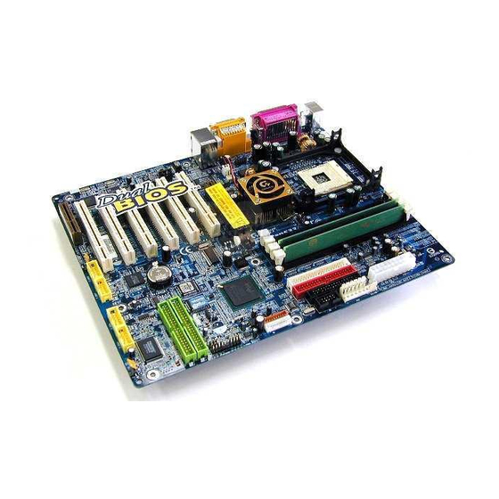
Page 12: Ga-8Ihxp Motherboard Layout
GA-8IHXP Motherboard GA-8IHXP Motherboard Layout KB / MS ATX_12V RAM_LED SOCKET478 GA-8IHXP F_Audio NB_FAN CPU_FAN 850E W83L 5180 PCI1 ICH4 CD_IN PCI2 AUX_IN CLR_CMOS CODEC ** MAIN BACKUP PCI3 SUR_CEN** IR_CIR BIOS BIOS BATTERY IDE4 8100BL PCI4 SPDIF_IN** SPDIF IDE3... -
Page 13: Chapter 2 Hardware Installation Process
Hardw are Installation Process Chapter 2 Hardware Installation Process To set up your computer, you must complete the following setups: Step 1- Install the Central Processing Unit (CPU) Step 2- Install memory modules Step 3- Install expansion cards Step 4- Connect ribbon cables, cabinet wires, and power supply Step 5- Setup BIOS software Step 6- Install supporting software tools Step 2... -
Page 14: Step 1: Install The Central Processing Unit (Cpu)
GA-8IHXP Motherboard Step 1: Install the Central Processing Unit (CPU) CPU Installation Pin1 indicator Pin1indicator CPU Top View CPU Bottom View Socket Actuation Lever Pin1 indicator 1. Pull up the CPU socket level 2. Locate Pin 1 in the socket and look and up to 90-degree angle. -
Page 15: Cpu Heat Sink Installation
Hardw are Installation Process CPU Heat Sink Installation 2. Make sure the CPU fan is plugged 1. Fasten the heatsink supporting-base to the CPU fan connector, than onto the CPU socket on the main- install complete. board. M Please use Intel approved cooling fan. M We recommend you to apply the thermal tape to provide better heat conduction between your CPU and heatsink. -
Page 16: Step 2: Install Memory Modules
GA-8IHXP Motherboard Step 2: Install memory modules The motherboard has 4 Rambus In-line Memory Module (RIMM) sockets. The BIOS will automati- cally detect memory type and size. To install the memory module, just push it vertically into the RIMM Slot .The RIMM module can only fit in one direction due to the two notches. Please note; Both RIMM modules inserted on RIMM1 and RIMM2 slots are recommended to have the same size, frequency. -
Page 17: Introduce Rimm (Rambus In-Line Memory Module)
Hardw are Installation Process Introduce RIMM (Rambus In-line Memory Module) Direct Rambus Memory Controller _Directly support a Dual Direct Rambus * Channel Supports 300&400 MHz Direct Rambus * Channel @ 100MHz host bus frequency. Maximum memory array size up t o 256MB using 64Mb/72Mb, 512MB using 128Mb/144Mb, 1GB using 256Mb/288Mb DRAM technology _Supports up to 32 Direct Rambus devices per channel _Supports a maximum DRAM address decode space of 4GB... -
Page 18: Step 3: Install Expansion Cards
GA-8IHXP Motherboard Step 3: Install expansion cards 1. Read the related expansion card’ s instruction document before install the expansion card into the computer. 2. Remove your computer’ s chassis cover, screws and slot bracket from the computer. 3. Press the expansion card firmly into expansion slot in motherboard. -
Page 19: Step 4: Connect Ribbon Cables, Cabinet Wires, And Powersupply
Hardw are Installation Process Step 4: Connect ribbon cables, cabinet wires, and power supply Step 4-1: I/O Back Panel Introduction u PS/2 Keyboard and PS/2 Mouse Connector PS/2 Mouse Connector ØThis connector supports standard PS/2 (6 pin Female) keyboard and PS/2 mouse. PS/2 Keyboard Connector (6 pin Female) v Parallel Port and Serial Ports (COMA/COMB) -
Page 20: Audio Connectors
GA-8IHXP Motherboard w Game /MIDI Ports ØThis connector supports joystick, MIDI keyboard and ot h er relate audio devices. Joystick/ MIDI (15 pin Female) x Audio Connectors Ø After install onboard audio driver, you may connect speaker to Line Out jack, micro phone to MIC In jack. -
Page 21: Step 4-2: Connectors Introduction
Hardw are Installation Process Step 4-2: Connectors Introduction A ATX _12V M WOL B PWR_FAN N IDE3/IDE4 C ATX O F_USB1~4 D RAM_LED P SPDIF E SYS_FAN Q BATTERY F AUX R IR_CIR G MS/SD/SC S AUX_IN H FDD/IDE1/IDE2 T CD_IN CLR_CMOS U CPU FAN J CI... - Page 22 GA-8IHXP Motherboard B / E / U : PWR_FAN / SYS_FAN / CPU_Fan Connector Sense +12V/Control +12V/Control Sense CPU_FAN SYS_FAN PWR_FAN Ø Please note, a proper installation of the CPU cooler is essential to prevent the CPU from running under abnormal condition or damaged by overheating.The CPU fan connector supports Max.
- Page 23 Hardw are Installation Process F: AUX Ø The 6-pin Aux. Power connector provides additional current to meet the board's +3.3VDC and +5VDC requirments. +3.3VDC Please refer to the detail on P.23 +3.3VDC +5VDC A: ATX_12V Power Connector Ø This connector (ATX_12V) suppliesthe CPU operation voltage (Vcore).
- Page 24 GA-8IHXP Motherboard R: IR_CIR Ø Make sure the pin 1 on the IR device is aling with pin one the connector. To enable the IR/CIR function on the board, you are required to purchase an option IR/ CIR module. For detail information please contact your autherized Giga-Byte distributor.
- Page 25 Hardw are Installation Process K: F_PANEL (2x10 pins jumper) GN (Green Switch) Open: Normal Operation Close: Entering Green Mode GD (Green LED) Pin 1: LED anode(+) Pin 2: LED cathode(-) HD (IDE Hard Disk Active LED) Pin 1: LED anode(+) Pin 2: LED cathode(-) SPK (Speaker Connector) Pin 1: VCC(+)
- Page 26 GA-8IHXP Motherboard O: F_USB1~ F_USB4 (Front USB Connector) (F_USB1 ~ F_USB4 connector in yellow are for USB 2.0) USB Dy+ USB Dy- Power USB Over Current Power USB Dx- USB Dx+ Ø Be careful with the polarity of the front panel USB connector. Check the pin assignment while you connect the front panel USB cable.
- Page 27 Hardw are Installation Process I : CLR_CMOS (Clear CMOS Function)# 1-2 close: Clear CMOS Ø Please note: You may clear the CMOS data to its default values by this jumper. 2-3 close: Normal "#" Default doesn’ t include the “Shunter” to prevent from improper use this jumper.
- Page 28 GA-8IHXP Motherboard X ) SPDIF_IN (*) Ø Use this feature only when your stereo system has digital output function. SPDIF IN Y ) SUR_CEN (*) Ø Please contact your nearest dealer for optional SUR_CEN cable. SUR OUT(R) BASS_OUT CENTER_OUT SUR OUT(L)
-
Page 29: Step 4-3: Atx 12V Power Supply Introduction
Hardw are Installation Process Step 4-3: ATX 12V Power Supply Introduction -Additional 4 pin connector for 12V voltage -Backward compatibility maintained with load sharing capability -Support 12V or 5V CPU VRs Check power supply if it is supported by ATX12V Power Supply. Additional dedicated 12V 4-pin power connector 6Pin auxiliary ATX power connector ATX power connector... - Page 30 GA-8IHXP Motherboard...
- Page 31 Hardw are Installation Process...
- Page 32 GA-8IHXP Motherboard...
-
Page 33: Chapter 3 Bios Setup
BIOS Setup Chapter 3 BIOS Setup BIOS Setup is an overview of the BIOS Setup Program. The program that allows users to modify the basic system configuration. This type of information is stored in battery-backed CMOS RAM so that it retains the Setup information when the power is turned off. -
Page 34: Control Keys
GA-8IHXP Motherboard c. Press<F12> to boot from Network. d. After power on the computer, pressing <Del> immediately during POST (Power On Self Test) it will allow you to enter AMI BIOS CMOS SETUP. CONTROL KEYS <á> Move to previous item <â>... -
Page 35: The Main Menu (For Example: Bios Ver. :F5A)
BIOS Setup GETTING HELP Main Menu The on-line description of the highlighted setup function is displayed at the bottom of the screen. Status Page Setup Menu / Option Page Setup Menu Press F1 to pop up a small help window that describes the appropriate keys to use and the possible selections for the highlighted item. -
Page 36: Standard Cmos Features
GA-8IHXP Motherboard Standard CMOS Features This setup page includes all the items in standard compatible BIOS. Advanced BIOS Features This setup page includes all the items of AMI special enhanced features. Advanced Chipset Features This setup page includes all the adjustable items of chipset special features. -
Page 37: Standard Cmos Features
BIOS Setup Standard CMOS Features AMI NEW SETUP UTILITY-VISION 3.31a Standard CMOS Features Setup Help Sy stem Time 22:31:24 Menu Lev el u Sy stem Date Mon, Feb 21 2002 Current Language English Boot Sector Virus Protection Disabled Floppy Driv e A 1.44M, 3.5 in. - Page 38 GA-8IHXP Motherboard FCurrent Language There are 7 languages available, include English, Japanese, French, Spanish, Germany, Simplified Chinese, Traditional Chinese. FBoot Sector Virus Protection If it is set t o enable, the category will flash on the screen when there is any attempt to wri t e to the boot sector or partition table of the hard disk drive.
- Page 39 BIOS Setup FPrimary Master, Slave / Secondary Master, Slave The category identifies the types of hard disk from drive C to F that has been installed in the computer. There are two types: auto type, and manual type. Manual type is user-definable; Auto type which will automatically detect HDD type.
-
Page 40: Advanced Bios Features
GA-8IHXP Motherboard Advanced BIOS Features AMI NEW SETUP UTILITY-VISION 3.31a Adv anced BIOS Features Setup Help Boot Dev ice Priority 1st Floppy : 1.44MB 3 2nd Disabled 3rd Disabled BIOS Flash Protection Auto Show Full Screen Logo Enabled Floppy Driv e Seek... - Page 41 BIOS Setup FFloppy Drive Seek During POST, BIOS will determi n e the floppy disk drive installed is 40 or 80 tracks. 360 K type is 40 tracks 720 K, 1.2 M and 1.44 M are all 80 tracks. BIOS searches for floppy disk driv e to determine it is 40 or 80 tracks. Note 8Enabled that BIOS can not tell from 720 K, 1.2 M or 1.44 M driv e ty pe as they are all 80tracks.
-
Page 42: Advanced Chipset Features
GA-8IHXP Motherboard Advanced Chipset Features AMI NEW SETUP UTILITY-VISION 3.31a Adv anced Chipset Features Setup Help Front Side Bus Clock (MHz) By Hardw are CPU Frequency Ratio 8.0x (Safe) RDRAM Bus Frequency Auto Vcore Voltage Original Ov er RIMM Voltage... - Page 43 BIOS Setup Set Front Side Bus Clock (MHz) to 133.66. 8133.66 Set Front Side Bus Clock (MHz) to 136.00. 8136.00 Set Front Side Bus Clock (MHz) to 138.00. 8138.00 Set Front Side Bus Clock (MHz) to 140.00. 8140.00 Set Front Side Bus Clock (MHz) to 142.00. 8142.00 Set Front Side Bus Clock (MHz) to 144.00.
- Page 44 GA-8IHXP Motherboard FVcore Voltage Original Vcore Voltage. (Default Value) 8Original Original Vcore Voltage +0.025V. 8+0.025V Original Vcore Voltage +0.050V. 8+0.050V Original Vcore Voltage +0.075V. 8+0.075V Original Vcore Voltage +0.100V. 8+0.100V FOver RIMM Voltage Disable this funciton. (Default Value) 8Disabled Enable Ov er RIMM Voltage function.
- Page 45 BIOS Setup FICH Delayed Transaction Enable PCI 2.1 features including release and delay ed transaction for the 8Enabled chipset.(Default Value) Disable this function. 8Disabled FDMA Collection Buffer Enable DMA collection buffer for LPC I/F and PC/PCI DMA.(Default Value) 8Enabled Disable this function. 8Disabled...
-
Page 46: Integrated Peripherals
GA-8IHXP Motherboard Integrated Peripherals AMI NEW SETUP UTILITY-VISION 3.31a Integrated Peripherals Setup Help OnBoard IDE Both IDE1 Conductor Cable Auto IDE2 Conductor Cable Auto OnBoard FDC Auto OnBoard Serial Port A Auto OnBoard Serial Port B Auto Serial Port B Mode... - Page 47 BIOS Setup AC97 Modem Auto Onboard USB2.0 Chip Enabled Onboard Lan Chip Enabled Onboard Sound Chip Enabled Onboard Promise Chip ESC :Prev ious Menu hi: Select Item PU/PD/+/-/:Modify F8:Dual BIOS/Q-Flash F5: Old Values F6:Fail-Safe Values F7:Optimized Values F10:Sav e & Ex it Figure 5: Integrated Peripherals FOnBoard IDE Disable OnBoard IDE.
- Page 48 GA-8IHXP Motherboard FOnboard Serial Port A BIOS w ill automatically setup the port A address. (Default Value) 8Auto Enable onboard Serial port A and address is 3F8. 83F8/COM1 Enable onboard Serial port A and address is 2F8. 82F8/COM2 Enable onboard Serial port A and address is 3E8.
- Page 49 BIOS Setup FOnboard Parallel Port Set On Board LPT port and address to 378. 8378 Set On Board LPT port and address to 278. 8278 Set On Board LPT port and address to 3BC. 83BC Set On Board LPT port Automatically. (Default Value) 8Auto Disable onboard Serial port A.
- Page 50 GA-8IHXP Motherboard FOnBoard MIDI Port Set 300 for MIDI Port. 8300 Set 310 for MIDI Port . 8310 Set 320 for MIDI Port. 8320 Set 330 for MIDI Port. (Default Value) 8330 Disabled this function. 8Disabled C Midi Port IRQ Select Set M idi Port IRQ to 5.
- Page 51 BIOS Setup FOnBoard SC Interface Disable onboard SC Interface. 8Disabled Enabled onboard SC Interface.(Default Value) 8Enabled FSmart Card IRQ Select 8IRQ 3 / 4 / 5 / 10 /11 (Default Value: 10) FOnBoard MS/S D Interface 8Memory Stick Set MS/SD Interface to Memory Stick.(Default v alue) 8Secure Digital Set MS/SD Interface to Secure Digital.
- Page 52 GA-8IHXP Motherboard FOnboard US B2.0 Chip Disable this function. 8Disabled Enable Onboard USB2.0 Chip function. (Default Value) 8Enabled FOnboard Lan Chip Disable this function. 8Disabled Enable Onboard Lan Chip function. (Default Value) 8Enabled FOnboard S ound Chip Disable this function.
-
Page 53: Power Management Feature
BIOS Setup Power Management Feature AMI NEW SETUP UTILITY-VISION 3.31a Pow er Management Feature Setup Help ACPI Sleep Ty pe S1/POS USB Dev Wakeup From S3 Disabled PS/2 Dev Wakeup From S3 Disabled Pow er LED in S1 State Blinking Suspend Time Out (Minute) Disabled Throttle Slow Clock Ratio... - Page 54 GA-8IHXP Motherboard FACPI Sleep Type Set ACPI Sleep Ty pe to S1/POS (Pow er On Suspend). (Default v alue) 8S1/POS Set ACPI Sleep Ty pe to S3/STR (Suspend To RAM). 8S3/STR FUSB Dev Wakeup From S3 Enable USB Dev ice Wakeup From S3.
- Page 55 BIOS Setup FModemRingOn/WakeOnLan Disable Modem Ring On / Wake On LAN function. 8Disabled The modem ring / LAN w ake up w ill bring the sy stem out of soft-off or 8Enabled suspend state if this option is set "Enabled". (Default Value) FPME Event Wake up Disable PME ev ent w ake up function.
- Page 56 GA-8IHXP Motherboard FPri. slave IDE Access Monitor Primary slav eIDE Access. 8Monitor Ignore Primary slav e IDE Access. (Default Value) 8Ignore FSec. Master IDE Access Monitor Secondary Master IDE Access. (Default Value) 8Monitor Ignore Secondary Master IDE Access. 8Ignore FSec. slave IDE Access Monitor Secondary slav e IDE Access.
-
Page 57: Pnp/Pci Configurations
BIOS Setup PNP/PCI Configurations AMI NEW SETUP UTILITY-VISION 3.31a PNP/PCI Configurations Setup Help VGA Boot From PCI Slot 1/5 IRQ Priority Auto PCI Slot 2/6 IRQ Priority Auto PCI Slot 3 IRQ Priority Auto PCI Slot 4 IRQ Priority Auto IRQ3 PCI/PnP IRQ4... - Page 58 GA-8IHXP Motherboard FPCI Slot1 /5, 2/6, 3, 4 IRQ Priority The sy stem w ill reserv ed a free IRQ for PCI slot 1/5, 2/6, 3, 4 dev ice. 8Auto (Default Value) The sy stem w ill reserv ed IRQ3 for PCI slot 1/5, 2/6, 3, 4 dev ice if no legacy ISA dev ice using IRQ3.
-
Page 59: Pc Health Status
BIOS Setup PC Health Status AMI NEW SETUP UTILITY-VISION 3.31a PC Health Status Setup Help CPU Temperature Alarm Disabled CPU Fan Fail Alarm Pow er Fan Fail Alarm Sy stem Fan Fail Alarm Reset Case Open Status Case Status Opened CPU Temperature 35°C/ 95°F Sy stem Temperature... - Page 60 GA-8IHXP Motherboard FFan Fai l Alarm CPU / Power / System Fan Fail Alarm Function Disable. (Default Value) Fan Fail Alarm Function Enable. 8Yes CReset Case Open Status CCase Opened If the case is closed, "Case Opened" w ill show "No".
-
Page 61: Set Supervisor / User Password
BIOS Setup Set Supervisor / User Password When you select this function, the following message will appear at the center of the screen to assist you in creating a password. AMI NEW SETUP UTILITY-VISION 3.31a }Standard CMOS Features Set Superv isor Passw ord }Adv anced BIOS Features Set User Passw ord }Adv anced Chipset Features... -
Page 62: Load Optimized Defaults
GA-8IHXP Motherboard Load Optimized Defaults AMI NEW SETUP UTILITY-VISION 3.31a }Standard CMOS Features Set Superv isor Passw ord }Adv anced BIOS Features Set User Passw ord }Adv anced Chipset Features Load Optimized Defaults }Integrated Peripherals Load Fail Safe Defaults [Load optimized settings] }Pow er Management Setup Sav e &... -
Page 63: Load Fail-Safe Defaults
BIOS Setup Load Fail-Safe Defaults AMI NEW SETUP UTILITY-VISION 3.31a }Standard CMOS Features Set Superv isor Passw ord }Adv anced BIOS Features Set User Passw ord }Adv anced Chipset Features Load Optimized Defaults }Integrated Peripherals Load Fail Safe Defaults [Load fail safe settings] }Pow er Management Setup Sav e &... -
Page 64: Save & Exit Setup
GA-8IHXP Motherboard Save & Exit Setup AMI NEW SETUP UTILITY-VISION 3.31a }Standard CMOS Features Set Superv isor Passw ord }Adv anced BIOS Features Set User Passw ord }Adv anced Chipset Features Load Optimized Defaults }Integrated Peripherals Load Fail Safe Defaults... -
Page 65: Exit Without Saving
BIOS Setup Exit Without Saving AMI NEW SETUP UTILITY-VISION 3.31a }Standard CMOS Features Set Superv isor Passw ord }Adv anced BIOS Features Set User Passw ord }Adv anced Chipset Features Load Optimized Defaults }Integrated Peripherals Load Fail Safe Defaults [Quit without saving changes] }Pow er Management Setup Sav e &... - Page 66 GA-8IHXP Motherboard...
- Page 67 BIOS Setup...
- Page 68 GA-8IHXP Motherboard...
-
Page 69: Chapter 4 Technical Reference
Technical Reference Revision History Chapter 4 Technical Reference Block Diagram Pentium 4 CPUCLK+/- (100/133MHz) Socket 478 AGP 4X System Bus AGPCLK 100/133MHz (66MHz) RDRAM 300/400/533MHz Intel MCH66 (66MHz) 6 PCI 82850E MCHCLK+/- (100MHz) RJ45 66 MHz 33 MHz 14.318 MHz 48 MHz RTL8100BL SST49LF004A... -
Page 70: Dual Bios / Q-Flash Introduction
GA-8IHXP Motherboard Dual BIOS / Q-Flash Introduction A. What is Dual BIOS Technology? Dual BIOS means that there are two system BIOS (ROM) on the motherboard, one is the Main BIOS and the other is Backup BIOS. Under the normal circumstances, the system works on the Main BIOS. - Page 71 Technical Reference b. Dual BIOS Utility Dual BIOS Utility Boot From..........Main BIOS Main ROM Type..........ST M50FW040 Backup ROM Type..........ST M50FW040 Wide Range Protection Disable Boot From MainBIOS Auto Recovery Enable Halt On Error Disable Copy Main ROM Data to Backup Load Default Settings Save Settings to CMOS Q-Flash Utility...
- Page 72 GA-8IHXP Motherboard Status 2: If the ROM BIOS on peripherals cards(ex. SCSI Cards, LAN Cards,..) emits signals to request restart of the system after the user make any alteration on it, the boot up BIOS will not be changed to the Backup BIOS.
- Page 73 Technical Reference D. How to use Q-Flash? Load Main (Backup) BIOS From Floppy !In the A:drive, insert the "BIOS" diskette, then Press Enter to Run. !You can use the light bar to select item. then Press "Enter". !For Example: BIOS File name: 7VRXP.E8 Dual BIOS Utility Boot From..........Main BIOS Main ROM Type..........SST 39SF020...
- Page 74 GA-8IHXP Motherboard !!COPY BIOS Complete-Pass!! Please press any key to continue Save Main (Backup) BIOS to Floppy !In the A:drive, insert the "BIOS" diskette, then Press Enter to Run. !You can use the light bar to select item. then Press "Enter".
- Page 75 GIGABYTE Technology is pleased to introduce DualBIOS technology, a hot spare for your system BIOS. This newest “ Value-added” feature, in a long series of innovations from GIGABYTE, is available on this motherboard. Future GIGABYTE motherboards will also incorporate this innovation.
- Page 76 GA-8IHXP Motherboard I. Q: What is DualBIOS technology? Answer: DualBIOS technology is a patented technology from Giga-Byte Technology. The concept of this technology is based on the redundancy and fault tolerance theory. DualBIOS technology simply means there are two system BIOSes (ROM) integrated onto the motherboard. One is a main BIOS, and the other is a backup BIOS.
- Page 77 Technical Reference III. Q: How does DualBIOS technology work? Answer: DualBIOS technology provides a wide range of protection during the boot up procedure. It protects your BIOS during system POST, ESCD update, and even all the way to PNP detection/assignment. DualBIOS provides automatic recovery for the BIOS.
- Page 78 GA-8IHXP Motherboard 2. During or after a BIOS upgrade, if DualBIOS detects that the main BIOS is corrupt, the backup BIOS will take over the boot-up process automatically. Moreover, it will verify the main and backup BIOS checksums when booting-up. DualBIOS...
-
Page 79: 4- / 6-Channel Audio Function Introuction
Technical Reference 2- / 4- / 6-Channel Audio Function Introuction The installation of Windows 98SE/2K/ME/XP is very simple. Please follow next step to install the function! Stereo Speakers Connection and Settings: We recommend that you use the speaker with amplifier to acqiire the best sound effect if the stereo output is applied. - Page 80 GA-8IHXP Motherboard 4 Channel Analog Audio Output Mode STEP 1 : Line Out Connect the front channels to "Line Out", the rear channels to "Line In". Line In STEP 2 : After installation of the audio driver, you'll find an icon on the taskbar's status area. Click the audio icon "Sound Effect"...
- Page 81 Technical Reference Basic 6 Channel Analog Audio Output Mode Use the back audio panel to connect the audio output without any additional module. STEP 1 : Line Out Connect the front channels to "Line Out", the rear Line In channels to "Line In", and the Center/Subwoofer channels to "MIC In".
- Page 82 GA-8IHXP Motherboard Advanced 6 Channel Analog Audio Output Mode (using SURROUND-KIT): "SURROUND-KIT" is an optional device, which ac- cess analog output to rear channels and Center/ Subwoofer channels. It is the best solution if you need 6 channel output, Line In and MIC at the same time.
- Page 83 Technical Reference STEP 3 : Connect the front channels to back audio panel's "Line Out", the rear channels to SURROUND-KIT's REAR R/L, and the Center/Subwoofer channels to SURROUND-KIT's SUB CENTER. STEP 4 : Click the audio icon "Sound Effect" from the win- dows tray at the bottom of the screen.
- Page 84 GA-8IHXP Motherboard SPDIF Output Device (Optional Device) A "S/PDIF output" device is available on the motherboard. Cable with rear bracket is provided and could link to the "S/PDIF output" connector (As picture.) For the further linkage to decoder, rear bracket provides coaxial cable and Fiber connect- ing port.
-
Page 85: Bios Introduction
BIOS directly. Or you may want to keep a backup for your current BIOS, just choose “ Save Current BIOS” to save it first. You make a wise choice to use Gigabyte, and @BIOS update your BIOS smartly. You are now worry free from updating wrong BIOS, and capable to maintain and manage your BIOS easily. -
Page 86: Easy Tune
Obviously, Gigabyte EasyTune 4 has already turned the "Overclock" technology toward to a newer generation. This wonderful software is now free bundled in Gigabyte motherboard attached in driver CD. Users may make a test drive of "EasyTune 4" to find out more amazing features by themselves. - Page 87 Technical Reference...
- Page 88 GA-8IHXP Motherboard...
-
Page 89: Chapter 5 Appendix
Appendix Revision History Chapter 5 Appendix Picture below are shown in Windows XP (IUCD driver version 2.11) Insert the driver CD-title that came with your motherboard into your CD-ROM driver, the driver CD-title will auto start and show the installation guide. If not, please double click the CD-ROM device icon in "My computer", and execute the setup.exe. - Page 90 GA-8IHXP Motherboard A-1. Intel Chipset Software Installation Utility Insert the driver CD-title that came with your motherboard into your CD-ROM driver, the driver CD-title will auto start and show the installation guide. If not, please double click the CD-ROM device icon in "My computer", and execute the setup.exe.
- Page 91 Appendix A-2. Intel Application Accelerator Insert the driver CD-title that came with your motherboard into your CD-ROM driver, the driver CD-title will auto start and show the installation guide. If not, please double click the CD-ROM device icon in "My computer", and execute the setup.exe. 1.Click "Intel Application Accelerator"...
- Page 92 A-4: USB 2.0 Driver for ICH4 (Expiry date: 6/1/2002) USB2.0 Driver Installation for ICH4 is the same with “NEC 2.0 Host Controller Driver” , please go to the gigabyte’ s website (http://www.gigabyte.com.tw) and download the latest ICH4 USB2.0 driver version after expiry date (6/1/2002).
- Page 93 Appendix Appendix B: RealTek AC’ 97 Audio Driver Revision History Insert the driver CD-title that came with your motherboard into your CD-ROM driver, the driver CD-title will auto start and show the installation guide. If not, please double click the CD-ROM device icon in "My computer", and execute the setup.exe.
- Page 94 GA-8IHXP Motherboard Appendix D: Other Device Driver D-1. Promise ATA133 Driver information (This manual assumes that your CD-ROM device drive letter is D:). 1.Click "Promise ATA133 Driver Information” item. If you want to install ATA133 Driver, go to “ Control Panel-->System-->Device Manager” and install driver by manually.
- Page 95 Appendix 4.Click "Update Driver" item. 5.Click "Next" item. 6.Click "Next" item. 7.Click "Finish " to restart computer.
- Page 96 GA-8IHXP Motherboard D-2. Winbond MS/SD/SCR Device Driver Insert the driver CD-title that came with your motherboard into your CD-ROM driver, the driver CD-title will auto start and show the installation guide. If not, please double click the CD-ROM device icon in "My computer", and execute the setup.exe.
- Page 97 Please refer to the following precedure: 2.Click "Update Driver" item. 3.Click "Next" item. 4.Click "Finish " to restart computer. If there is any problem occurred during USB2.0 device installing, using or upgrading. Please visit Microsoft or GIGABYTE website for downloading the latest drivers.
- Page 98 GA-8IHXP Motherboard Appendix E: EasyTune 4 Utilities Installation Revision History Insert the driver CD-title that came with your motherboard into your CD-ROM driver, the driver CD-title will auto start and show the installation guide. If not, please double click the CD-ROM device icon in "My computer", and execute the setup.exe.
- Page 99 What is Face-Wizard Face-Wizard is a windows based utility with user-friendly interface that allows users to change the boot-up logo with picture from Gigabyte Logo Gallery on web site or other compatible picture you have. How does it work? Face-Wizard allows user to select BIOS on board or file in hard drive, floppy disk , zip, MO or other storage devices and combine the compatible picture you prefer into BIOS.
- Page 100 GA-8IHXP Motherboard 2.Click "Help" icom.
- Page 101 Appendix Appendix G: BIOS Flash Procedure BIOS update procedure: Method 1: If your OS is Win9X, we recommend that you used Gigabyte @BIOS Program to flash BIOS. Press "Tools" icon. 2.Click "@BIOS Writer Utility v.1.08q". 1.Click "Gigabyte Utilities". Click here.
- Page 102 In method I, if the BIOS file you need cannot be found in @BIOS server, please go onto Gigabyte's web site for downloading and updating it according to method II. d. Please note that any interruption during updating will cause system unbooted...
- Page 103 Appendix Method 2: We use GA-7VTX motherboard and Flash841 BIOS flash utility as example. Please flash the BIOS according to the following procedures if you are now under the DOS mode. Flash BIOS Procedure: STEP 1: (1) Please make sure your system has installed the extraction utility such as winzip or pkunzip. Firstly you have to install the extraction utility such as winzip or pkunzip for unzip the files.
- Page 104 GA-8IHXP Motherboard (2) Select the "Quick (erase)" for Format Type, and pick both "Display summary when finished" and "Copy system files", after that press "Start". That will format the floppy and transfer the needed system files to it. Beware: This procedure will erase all the prior data on that floppy, so please proceed accordingly.
- Page 105 Appendix STEP 3: Download BIOS and BIOS utility program. (1) Please go to Gigabyte website http://www.gigabyte.com.tw/index.html, and click "Support". (2) From Support zone, click the "Motherboards BIOS & Drivers".
- Page 106 GA-8IHXP Motherboard (3) We use GA-7VTX motherboard as example. Please select GA-7VTX by Model or Chipset optional menu to obtain BIOS flash files. (4) Select an appropriate BIOS version (For example: F4), and click to download the file. It will pop...
- Page 107 Appendix (5) At this time the screen shows the following picture, please click "Extract" button to unzip the files. (6) Please extract the download files into the clean bootable floppy disk A mentioned in STEP 2, and press "Extract".
- Page 108 GA-8IHXP Motherboard STEP 4: Make sure the system will boot from the floppy disk. (1) Insert the floppy disk (contains bootable program and unzip file) into the floppy drive A. Then, restart the system. The system will boot from the floppy disk. Please press <DEL> key to enter BIOS setup main menu when system is boot up.
- Page 109 Appendix (3) Press "Enter" to enter "BIOS FEATURES SETUP" menu. Use the arrows to highlight the item "1st Boot Device", and then use the "Page Up" or "Page Down" keys to select "Floppy". AMIBIOS SETUP - BIOS FEATURES SETUP ( C ) 2001 American Megatrends, Inc. All Rights Reserved 1st Boot Device : Floppy 2nd Boot Device...
- Page 110 GA-8IHXP Motherboard STEP 5: BIOS flashing. (1) After the system boot from floppy disk, type "A:\> dir/w" and press "Enter" to check the entire files in floppy A. Then type the "BIOS flash utility" and "BIOS file" after A:\>. In this case you have to type "A:\>...
- Page 111 Appendix (3) It will pop up a screen and asks "Are you sure to flash the BIOS?" Press [Enter] to continue the procedure, or press [ESC] to quit. Beware: Please do not turn off the system while you are upgrading BIOS. It will render your BIOS corrupted and system totally inoperative.
- Page 112 GA-8IHXP Motherboard STEP 6: Load BIOS defaults. Normally the system redetects all devices after BIOS has been upgraded. Therefore, we highly recommend reloading the BIOS defaults after BIOS has been upgraded. This important step resets everything after the flash. (1) Take out the floppy diskette from floppy drive, and then restart the system. The boot up screen will indicate your motherboard model and current BIOS version.
- Page 113 Appendix (3) Use the arrows to highlight the item "SAVE & EXIT SETUP" and press "Enter". System will ask "SAVE to CMOS and EXIT (Y/N)?" Press "Y" and "Enter" keys to confirm. Now the system will reboot automatically, the new BIOS setting will be taken effect next boot-up. AMIBIOS SIMPLE SETUP UTILITY - VERSION 1.24b (C) 2001 American Megatrends, Inc.
- Page 114 GA-8IHXP Motherboard Appendix H: Acronyms Acronyms Meaning ACPI Advanced Configuration and Power Interface AP M Advanced Power Management Accelerated Graphics Port Audio Modem Riser Advanced Communications Riser BIOS Basic Input / Output System C P U Central Processing Unit CMOS...
- Page 115 Appendix Acronyms Meaning Logical Block Addressing Light Emitting Diode MH z Megahertz MIDI Musical Instrument Digital Interface Memory Translator Hub Memory Protocol Translator Network Interface Card Operating System Original Equipment Manufacturer PCI A.G.P. Controller POST Power-On Self Test Peripheral Component Interconnect RIMM Rambus in-line Memory Module Special Circumstance Instructions...
- Page 116 GA-8IHXP Motherboard Technical Support/RMA Sheet Customer/Country: Company: Phone No.: Contact Person: E-mail Add. : Model name/Lot Number: PCB revision: BIOS version: O.S./A.S.: Hardware Mfs. Model name Size: Driver/Utility: Configuration C P U Memory Brand Video Card Audio Card CD-ROM /...
- Page 117 MEMO...
- Page 118 GA-8IHXP Motherboard...
- Page 119 MEMO...
- Page 120 GA-8IHXP Motherboard...
- Page 121 MEMO...
- Page 122 GA-8IHXP Motherboard...
- Page 123 MEMO...
- Page 124 GA-8IHXP Motherboard...
- Page 125 MEMO...
- Page 126 GA-8IHXP Motherboard...
- Page 127 MEMO...
- Page 128 GA-8IHXP Motherboard...