Table of Contents
Advertisement
When you installing AGP card, please make sure the following notice
is fully understood and practiced. If your AGP card has "AGP 4X/8X
(1.5V) notch"(show below), please make sure your AGP card is AGP
4X/8X (1.5V).
AGP 4X/8X notch
Caution: AGP 2X card is not supported by Intel
845(GE/PE) / 845(E/G) /
®
850(E) / E7205 / 865(G/PE/P) / 875P. You might experience system
unable to boot up normally. Please insert an AGP 4X/8X card.
Example 1: Diamond Vipper V770 golden finger is compatible with 2X/4X
mode AGP slot. It can be switched between AGP 2X(3.3V) or 4X(1.5V) mode
by adjusting the jumper. The factory default for this card is 2X(3.3V).
The GA-8IG1000MK (or any AGP 4X/8X only) motherboards might not
function properly, if you install this card without switching the jumper to
4X(1.5V) mode in it.
Example 2: Some ATi Rage 128 Pro graphics cards made by "Power Color",
the graphics card manufacturer & some SiS 305 cards, their golden finger is
compatible with 2X(3.3V)/4X(1.5V) mode AGP slot, but they support 2X(3.3V)
only. The GA-8IG1000MK (or any AGP 4X/8X only) motherboards might not
function properly, If you install this card in it.
Note : Although Gigabyte's AG32S(G) graphics card is based on ATi Rage
128 Pro chip, the design of AG32S(G) is compliance with AGP 4X(1.5V)
specification. Therefore, AG32S(G) will work fine with Intel
845(GE/PE) /
®
845(E/G) / 850(E) / E7205 / 865(G/PE/P) / 875P based motherboards.
Advertisement
Table of Contents

Related Manuals for Gigabyte GA-8IG1000MK


Summary of Contents for Gigabyte GA-8IG1000MK
- Page 1 & some SiS 305 cards, their golden finger is compatible with 2X(3.3V)/4X(1.5V) mode AGP slot, but they support 2X(3.3V) only. The GA-8IG1000MK (or any AGP 4X/8X only) motherboards might not function properly, If you install this card in it.
- Page 2 The author assumes no responsibility for any errors or omissions that may appear in this document nor does the author make a commitment to update the information contained herein. Third-party brands and names are the property of their respective owners. Please do not remove any labels on motherboard, this may void the warranty of this motherboard.
- Page 3 Motherboard GA-8IG1000MK (2.0) Aug. 24, 2005...
- Page 4 Motherboard GA-8IG1000MK (2.0) Aug. 24, 2005...
- Page 5 GA-8IG1000MK (rev. 2.0) P4 Titan Series Motherboard USER'S MANUAL Pentium 4 Processor Motherboard ® Rev. 2002 12ME-8IG1KMK-2002R...
-
Page 6: Table Of Contents
Table of Contents Warning ....................4 Chapter 1 Introduction ................5 Features Summary ..................5 GA-8IG1000MK(rev. 2.0) Motherboard Layout ........... 7 Block Diagram ..................... 8 Chapter 2 Hardware Installation Process ..........11 Step 1: Install the Central Processing Unit (CPU) ........12 Step 1-1: CPU Installation .................... - Page 7 Frequency/Voltage Control ................ 52 Load Fail-Safe Defaults ................54 Load Optimized Defaults ................55 Set Supervisor/User Password ..............56 Save & Exit Setup ..................57 Exit Without Saving ................... 58 Chapter 4 Technical Reference ............61 @BIOS Introduction ................. 61 ™...
-
Page 8: Warning
PCB surface, because the circuit wire may be near by the hole. Be careful, don't let the screw contact any printed circuit write or parts on the PCB that are near the fixing hole, otherwise it may damage the board or cause board malfunctioning. GA-8IG1000MK(rev. 2.0) Motherboard - 4 -... -
Page 9: Chapter 1 Introduction
Chapter 1 Introduction Features Summary Form Factor 24.3cm x 24.3cm Micro ATX size form factor, 4 layers PCB Socket 478 for Intel Micro FC-PGA2 Pentium 4 processor ® ® Support Intel Pentium 4 (Northwood, Prescott) processor ® ® Support Intel Pentium 4 Processor with HT Technology * ®... - Page 10 CPU, chipset and most of the peripherals. Whether your system can run under these specific bus frequencies properly will depend on your hardware configurations, including CPU, Chipsets, SDRAM, Cards…etc. (Note 2) EasyTune functions may vary depending on different motherboards. GA-8IG1000MK(rev. 2.0) Motherboard - 6 -...
-
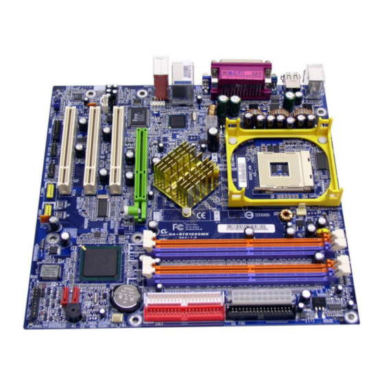
Page 11: Ga-8Ig1000Mk(Rev. 2.0) Motherboard Layout
GA-8IG1000MK(rev. 2.0) Motherboard Layout KB_MS RAM_LED R_USB CPU_FAN SOCKET 478 ATX_12V Intel 82562 AUDIO1 Intel 865G COMB 2X_DET ITE8712 PCI1 SYS _FAN CLR_PWD CD_IN Intel ICH5 SUR_CEN AUX_IN PCI2 SATA1 CODEC PCI3 Buzzer SATA0 BIOS PWR_LED GAME IR_CIR INFO_LINK F_USB1... -
Page 12: Block Diagram
ATA33/66/100 2 COM Ports AC97 IDE Channels CODEC 8 USB 2 Serial ATA Ports PCICLK (33MHz) PCICLK (33MHz) CPUCLK+/- (100/133/200MHz) USBCLK (48MHz) AGPCLK (66MHz) CLK GEN 14.318 MHz MCHCLK (100/133/200mHz) 33 MHz ICH3V66 (66MHz) GA-8IG1000MK(rev. 2.0) Motherboard - 8 -... - Page 13 - 9 - Introduction...
- Page 14 GA-8IG1000MK(rev. 2.0) Motherboard - 10 -...
-
Page 15: Chapter 2 Hardware Installation Process
Chapter 2 Hardware Installation Process To set up your computer, you must complete the following steps: Step 1- Install the Central Processing Unit (CPU) Step 2- Install memory modules Step 3- Install expansion cards Step 4- Connect ribbon cables, cabinet wires, and power supply Step 1 Step 4 Step 2... -
Page 16: Step 1: Install The Central Processing Unit (Cpu)
Pin1 indicator Pin1 indicator 4. Locate Pin 1 in the socket and 3. CPU Top View look for a (golden) cut edge on the CPU upper corner. Then insert the CPU into the socket. GA-8IG1000MK(rev. 2.0) Motherboard - 12 -... -
Page 17: Step 1-2: Cpu Cooling Fan Installation
Step 1-2: CPU Cooling Fan Installation Before installing the CPU cooling fan, adhere to the following warning: 1. Please use Intel approved cooling fan. 2. We recommend you to apply the thermal tape to provide better heat conduction between your CPU and cooling fan. (The CPU cooling fan might stick to the CPU due to the hardening of the thermal paste. -
Page 18: Step 2: Install Memory Modules
Then push it down. 3. Close the plastic clip at both edges of the DIMM sockets to lock the DIMM module. Reverse the installation steps when you wish to remove the DIMM module. GA-8IG1000MK(rev. 2.0) Motherboard - 14 -... -
Page 19: Ddr Introduction
PCs. Dual Channel Memory Configuration The GA-8IG1000MK supports the Dual Channel Technology. After operating the Dual Channel Technology, the bandwidth of Memory Bus will add double. GA-8IG1000MK includes four DIMM slots, and each Channel has 2 DIMMs as following:... -
Page 20: Step 3: Install Expansion Cards
When an AGP 2X (3.3V) card is installed the 2X_DET will light up, indicating a non-supported graphics card is inserted. Informing users that system might not boot up normally due to AGP 2X (3.3V) is not supported by the chipset. GA-8IG1000MK(rev. 2.0) Motherboard - 16 -... -
Page 21: Step 4: Connect Ribbon Cables, Cabinet Wires And Power Supply
Step 4: Connect ribbon cables, cabinet wires and power supply Step 4-1: I/O Back Panel Introduction PS/2 Keyboard and PS/2 Mouse Connector This connector supports standard PS/2 PS/2 Mouse Connector keyboard and PS/2 mouse. (6 pin Female) PS/2 Keyboard Connector (6 pin Female) USB/LAN Connector Before you connect your device(s) into USB... -
Page 22: Audio Connectors
Connect "Center and Subwoofer" to "MIC Out ". Method2: You can refer to page 28, and contact your nearest dealer for optional SUR_CEN cable. If you want the detail information for 2-/4-/6-channel audio setup installation, please refer to page 67. GA-8IG1000MK(rev. 2.0) Motherboard - 18 -... -
Page 23: Step 4-2: Connectors Introduction
Step 4-2: Connectors Introduction 1) ATX_12V 13) F_AUDIO 2) ATX 14) CD_IN 3) CPU_FAN 15) AUX_IN 4) SYS_FAN 16) SUR_CEN 5) FDD 17) F_USB1 / F_USB2 6) IDE1 / IDE2 18) COMB 7) SATA0 / SATA1 19) IR_CIR 8) BAT 20) GAME 9) F_PANEL 21) INFO_LINK... - Page 24 AC power cord should only be connected to your power supply unit after ATX power cable and other related devices are firmly connected to the mainboard. Pin No. Definition 3.3V 3.3V Power Good 5V SB (stand by +5V) +12V 3.3V -12V PS_ON(soft on/off) GA-8IG1000MK(rev. 2.0) Motherboard - 20 -...
- Page 25 3) CPU_FAN (CPU Fan Connector) Please note, a proper installation of the CPU cooler is essential to prevent the CPU from running under abnormal condition or damaged by overheating. The CPU fan connector supports Max. current up to 600 mA. Pin No.
- Page 26 6) IDE1 / IDE2 (IDE1 / IDE2 Connector) Important Notice: Please connect first hard disk to IDE1 and connect CD-ROM to IDE2. The red stripe of the ribbon cable must be the same side with the Pin1. IDE2 IDE1 GA-8IG1000MK(rev. 2.0) Motherboard - 22 -...
- Page 27 7) SATA0 / SATA1 (Serial ATA Connector) Serial ATA can provide up to 150MB/s transfer rate. Please refer to the BIOS setting for the Serial ATA and install the proper driver in order to work properly. Pin No. Definition SATA1 SATA0 8) BAT (BATTERY) CAUTION...
- Page 28 Open: Normal Operation (Green) Close: Reset Hardware System PW (Power Switch) Open: Normal Operation (Red) Close: Power On/Off MSG (Message LED/ Power/ Sleep LED) Pin 1: LED anode(+) (Yellow) Pin 2: LED cathode(-) NC (Purple) GA-8IG1000MK(rev. 2.0) Motherboard - 24 -...
- Page 29 10) PWR_LED PWR_LED is connect with the system power indicator to indicate whether the system is on/off. It will blink when the system enters suspend mode. If you use dual color LED, power LED will turn to another color. Pin No. Definition MPD+ MPD-...
- Page 30 Please note, you can have the alternative of using front audio connector or of using rear audio connector to play sound. Pin No. Definition MIC_BIAS Power Front Audio (R) Rear Audio(R)/Return R Reserved No Pin Front Audio (L) Rear Audio(L)/Return L GA-8IG1000MK(rev. 2.0) Motherboard - 26 -...
- Page 31 14) CD_IN (CD In Connector) Connect CD-ROM or DVD-ROM audio out to the connector. Pin No. Definition CD-L CD-R 15) AUX_IN (AUX In Connector) Connect other device (such as PCI TV Tunner audio out) to the connector. Pin No. Definition AUX-L AUX-R - 27 -...
- Page 32 Be careful with the polarity of the front USB connector. Check the pin assignment while you connect the front USB cable. Please contact your nearest dealer for optional front USB cable. F_USB1 F_USB2 Pin No. Definition Power Power USB Dx- USB Dy- USB Dx+ USB Dy+ No Pin GA-8IG1000MK(rev. 2.0) Motherboard - 28 -...
- Page 33 Make sure the pin 1 on the IR device is aling with pin one the connector. To enable the IR/CIR function on the board, you are required to purchase an option IR/CIR module. For detail information please contact your autherized Gigabyte distributor. To use IR function only, please connect IR module to Pin1 to Pin5.
- Page 34 GPY1_R Power GPSB1 MSO_R GPSB2 No Pin 21) INFO_LINK This connector allows you to connect some external devices to provide you extra function. Pin No. Definition SMBCLK Power SMBDATA GPIO No Pin +12V +12V GA-8IG1000MK(rev. 2.0) Motherboard - 30 -...
- Page 35 22) CI (CASE OPEN) This 2-pin connector allows your system to enable or disable the "Case Open" item in BIOS, if the system case begin remove. Pin No. Definition Signal 23) CLR_PWD When Jumper is set to "open" and system is restarted, the password that is set will be cleared. On the contrary when Jumper is set to "close", the current status remains.
- Page 36 GA-8IG1000MK(rev. 2.0) Motherboard - 32 -...
-
Page 37: Chapter 3 Bios Setup
BIOS needs to be reset to its original settings. If you wish to upgrade to a new BIOS, either Gigabyte's Q-Flash or @BIOS utility can be used. Q-Flash allows the user to quickly and easily update or backup BIOS without entering the operating system. -
Page 38: The Main Menu (For Example: Bios Ver. : G1)
This setup page includes all the items of Green function features. PnP/PCI Configurations This setup page includes all the configurations of PCI & PnP ISA resources. PC Health Status This setup page is the System auto detect Temperature, voltage, fan, speed. GA-8IG1000MK(rev. 2.0) Motherboard - 34 -... -
Page 39: Load Optimized Defaults
Frequency/Voltage Control This setup page is control CPU’s clock and frequency ratio. Load Fail-Safe Defaults Fail-Safe Defaults indicates the value of the system parameters which the system would be in safe configuration. Load Optimized Defaults Optimized Defaults indicates the value of the system parameters which the system would be in best performance configuration. -
Page 40: Standard Cmos Features
Manual User can manually input the correct settings. Access Mode Use this to set the access mode for the hard drive. The four options are: CHS/LBA/Large/Auto(default:Auto) GA-8IG1000MK(rev. 2.0) Motherboard - 36 -... - Page 41 IDE Channel 2/3 Master IDE HDD Auto-Detection Press "Enter" to select this option for automatic device detection. Extended IDE Drive SATA IDE devices setup. You can use one of two methods: Auto Allows BIOS to automatically detect IDE devices during POST. (Default value) None Select this if no IDE devices are used and the system will skip the automatic...
-
Page 42: Base Memory
The BIOS determines how much extended memory is present during the POST. This is the amount of memory located above 1MB in the CPU's memory address map. Total Memory This item displays the memory size that used. GA-8IG1000MK(rev. 2.0) Motherboard - 38 -... -
Page 43: Advanced Bios Features
Advanced BIOS Features CMOS Setup Utility-Copyright (C) 1984-2005 Award Software Advanced BIOS Features Hard Disk Boot Priority [Press Enter] Item Help First Boot Device [Floppy] Menu Level Second Boot Device [Hard Disk] Third Boot Device [CDROM] Select Hard Disk Boot Password Check [Setup] Device Priority... -
Page 44: Password Check
Set onboard VGA frame buffer as 1MB. Set onboard VGA frame buffer as 4MB. Set onboard VGA frame buffer as 8MB. 16MB Set onboard VGA frame buffer as 16MB. (Default value) 32MB Set onboard VGA frame buffer as 32MB. GA-8IG1000MK(rev. 2.0) Motherboard - 40 -... -
Page 45: Integrated Peripherals
Integrated Peripherals CMOS Setup Utility-Copyright (C) 1984-2005 Award Software Integrated Peripherals On-Chip Primary PCI IDE [Enabled] Item Help On-Chip Secondary PCI IDE [Enabled] Menu Level On-Chip SATA [Auto] x SATA Port0 Configure as SATA Port0 SATA Port1 Configure as SATA Port1 USB Controller [Enabled] USB 2.0 Controller... -
Page 46: Usb Controller
Disable this function if you are not using onboard USB 2.0 feature. Enabled Enable USB 2.0 Controller. (Default value) Disabled Disable USB 2.0 Controller. USB Keyboard Support Enabled Enable USB Keyboard Support. Disabled Disable USB Keyboard Support. (Default value) GA-8IG1000MK(rev. 2.0) Motherboard - 42 -... -
Page 47: Ac97 Audio
USB Mouse Support Enabled Enable USB Mouse Support. Disabled Disable USB Mouse Support. (Default value) AC97 Audio Auto Auto detect AC'97 audio function. (Default Value) Disabled Disable AC'97 audio function. Onboard H/W LAN Enabled Enable Onboard H/W LAN function. (Default value) Disabled Disable this function. -
Page 48: Uart Mode Select
This feature allows you to select Direct Memory Access(DMA) channel if the ECP mode selected. This function will available when "Parallel Port Mode" set at ECP or ECP+EPP. Set ECP Mode Use DMA to 3. (Default Value) Set ECP Mode Use DMA to 1. GA-8IG1000MK(rev. 2.0) Motherboard - 44 -... -
Page 49: Game Port Address
Game Port Address Set Game Port Address to 201. (Default Value) Set Game Port Address to 209. Disabled Disable this function. Midi Port Address Set Midi Port Address to 300. Set Midi Port Address to 330. Disabled Disable this function. (Default Value) Midi Port IRQ Set Midi Port IRQ to 5. -
Page 50: Power Management Setup
Delay 4 Sec. Press power button 4 sec. to Power off. Enter suspend if button is pressed less than 4 sec. PME Event Wake Up Disabled Disable this function. Enabled Enable PME Event Wake up. (Default Value) GA-8IG1000MK(rev. 2.0) Motherboard - 46 -... -
Page 51: Resume By Alarm
ModemRingOn/WakeOnLAN An incoming call via modem can awake the system from any suspend state or an input signal comes from the other client server on the LAN can awake the system from any suspend state. Disabled Disable Modem Ring on/wake on Lan function. Enabled Enable Modem Ring on/wake on Lan. -
Page 52: Kb Power On Password
When AC-power back to the system, the system will be in "Off" state. (Default Value) Full-On When AC-power back to the system, the system always in "On" state. Memory When AC-power back to the system, the system will return to the Last state before AC-power off. GA-8IG1000MK(rev. 2.0) Motherboard - 48 -... -
Page 53: Pnp/Pci Configurations
PnP/PCI Configurations CMOS Setup Utility-Copyright (C) 1984-2005 Award Software PnP/PCI Configurations PCI 1 IRQ Assignment [Auto] Item Help PCI 2 IRQ Assignment [Auto] Menu Level PCI 3 IRQ Assignment [Auto] Device(s) using this INT: : Move Enter: Select +/-/PU/PD: Value F10: Save ESC: Exit F1: General Help... -
Page 54: Pc Health Status
Current Voltage (V) Vcore / DDR25V / +3.3V / +5V / +12V Detect system's voltage status automatically. Current CPU Temperature Detect CPU Temp. automatically. Current CPU/SYSTEM FAN Speed (RPM) Detect CPU/SYSTEM Fan speed status automatically. GA-8IG1000MK(rev. 2.0) Motherboard - 50 -... -
Page 55: Cpu Warning Temperature
CPU Warning Temperature C / 140 Monitor CPU temperature at 60 C / 140 C / 158 Monitor CPU temperature at 70 C / 158 C / 176 Monitor CPU temperature at 80 C / 176 C / 194 Monitor CPU temperature at 90 C / 194 Disabled Disable this function.(Default value) -
Page 56: Frequency/Voltage Control
If you use a 400Mhz FSB processor, please set CPU Host Frequency to 100Mhz. If you use a 533Mhz FSB processor, please set CPU Host Frequency to 133Mhz. If you use an 800Mhz FSB processor, please set CPU Host Frequency to 200Mhz. GA-8IG1000MK(rev. 2.0) Motherboard - 52 -... - Page 57 AGP/PCI/SRC Fixed Adjust AGP/PCI/SRC clock asynchronous with CPU. Memory Frequency For Wrong frequency may make system can't boot, clear CMOS to overcome wrong frequency issue. for FSB(Front Side Bus) frequency =400Mhz, Memory Frequency = Host clock X 2.0. 2.66 Memory Frequency = Host clock X 2.66. Auto Set Memory frequency by DRAM SPD data.
-
Page 58: Load Fail-Safe Defaults
MB Intelligent Tweaker(M.I.T.) ESC: Quit : Select Item F8: Q-Flash F10: Save & Exit Setup Load Fail-Safe Defaults Fail-Safe defaults contain the most appropriate values of the system parameters that allow minimum system performance. GA-8IG1000MK(rev. 2.0) Motherboard - 54 -... -
Page 59: Load Optimized Defaults
Load Optimized Defaults CMOS Setup Utility-Copyright (C) 1984-2005 Award Software Standard CMOS Features Load Fail-Safe Defaults Advanced BIOS Features Load Optimized Defaults Integrated Peripherals Set Supervisor Password Power Management Setup Set User Password Load Optimized Defaults (Y/N)? N PnP/PCI Configurations Save &... -
Page 60: Set Supervisor/User Password
Setup Menu. If you select "Setup" at "Password Check" in Advance BIOS Features Menu, you will be prompted only when you try to enter Setup. GA-8IG1000MK(rev. 2.0) Motherboard - 56 -... -
Page 61: Save & Exit Setup
Save & Exit Setup CMOS Setup Utility-Copyright (C) 1984-2005 Award Software Standard CMOS Features Load Fail-Safe Defaults Advanced BIOS Features Load Optimized Defaults Integrated Peripherals Set Supervisor Password Power Management Setup Set User Password Save to CMOS and EXIT (Y/N)? Y PnP/PCI Configurations Save &... -
Page 62: Exit Without Saving
ESC: Quit : Select Item F8: Q-Flash F10: Save & Exit Setup Abandon all Data Type "Y" will quit the Setup Utility without saving to RTC CMOS. Type "N" will return to Setup Utility. GA-8IG1000MK(rev. 2.0) Motherboard - 58 -... - Page 63 - 59 - BIOS Setup...
- Page 64 GA-8IG1000MK(rev. 2.0) Motherboard - 60 -...
-
Page 65: Chapter 4 Technical Reference
Or you may want to keep a backup for your current BIOS, just choose "Save Current BIOS" to save it first. You make a wise choice to use Gigabyte, and @BIOS update your BIOS smartly. You are now worry free from updating wrong BIOS, and capable to maintain and manage your BIOS easily. -
Page 66: Easytune ™ 5 Introduction
Toggles between Easy and Advance Mode Display screen Display panel of CPU frequency Function display LEDs Shows the current functions status GIGABYTE Logo Log on to GIGABYTE website Help button Display EasyTune 5 Help file Exit or Minimize button Quit or Minimize EasyTune 5 software (Note) EasyTune 5 functions may vary depending on different motherboards. -
Page 67: Flash Bios Method Introduction
Flash BIOS Method Introduction Method 1 : Q-Flash A. What is Q-Flash Utility? Q-Flash utility is a pre-O.S. BIOS flash utility enables users to update its BIOS within BIOS mode, no more fooling around any OS. B. How to use Q-Flash? a. - Page 68 [Enter] to contiune or [ESC] to abort ... Press Enter to Run. !! Copy BIOS Completed - Pass !! Please press any key to continue ... Congratulation! You have completed the flashed and now can restart system. GA-8IG1000MK(rev. 2.0) Motherboard - 64 -...
- Page 69 Method 2 : @BIOS Utility If you don't have DOS boot disk, we recommend that you used Gigabyte @BIOS program to flash ™ BIOS. Press here. 2. Click Start/ All Programs/ Gigabyte/ @BIOS. 1. Click "@BIOS" item. 3.Click " ".
- Page 70 In method I, if the BIOS file you need cannot be found in @BIOS server, please go onto ™ Gigabyte's web site for downloading and updating it according to method II. d. Please note that any interruption during updating will cause system unbooted GA-8IG1000MK(rev. 2.0) Motherboard...
-
Page 71: 4- / 6-Channel Audio Function Introduction
2- / 4- / 6-Channel Audio Function Introduction The installation of Windows 98SE/2K/ME/XP is very simple. Please follow next step to install the function! Stereo Speakers Connection and Settings: We recommend that you use the speaker with amplifier to acqiire the best sound effect if the stereo output is applied. - Page 72 4 speakers out put". Disable "Only SURROUND-KIT", and press "OK". When the "Environment settings" is "None", the sound would be performed as stereo mode (2 chan- nels output). Please select the other settings for 4 channels output. GA-8IG1000MK(rev. 2.0) Motherboard - 68 -...
- Page 73 Basic 6 Channel Analog Audio Output Mode Use the back audio panel to connect the audio output without any additional module. STEP 1 : Connect the front channels to "Line Out", the rear Line In channels to "Line In", and the Center/Subwoofer channels to "MIC In".
- Page 74 MIC at the same time. STEP 1 : Insert the "SURROUND-KIT" in the back of the case, and fix it with the screw. STEP 2 : Connect the "SURROUND-KIT" to SUR_CEN on the motherboard. GA-8IG1000MK(rev. 2.0) Motherboard - 70 -...
- Page 75 STEP 3 : Connect the front channels to back audio panel's "Line Out", the rear channels to SURROUND-KIT's REAR R/L, and the Center/Subwoofer channels to SURROUND-KIT's SUB CENTER. STEP 4 : Click the audio icon "Sound Effect" from the win- dows tray at the bottom of the screen.
-
Page 76: Jack-Sensing Introduction
Please connect the devices to the right jacks as above. A window will appear as right picture if you setup the devices properly. Please note that 3D audio function will only appear when 3D audio inputs. GA-8IG1000MK(rev. 2.0) Motherboard - 72 -... - Page 77 If you set wrong with the connectors, the warning message will come out as right picture. Manual setting: If the device picture shows different from what you set, please press "Manual Selection" to set. - 73 - Technical Reference...
-
Page 78: Xpress Recovery2 Introduction
2. System storage capacity and the reading/writing speed of the hard disk will affect the data backup speed. 3. It is recommended that Xpress Recovery2 be immediately installed once you complete installations of OS and all required drivers as well as software. GA-8IG1000MK(rev. 2.0) Motherboard - 74 -... - Page 79 The Main Screen of Xpress Recovery2 1. RESTORE: Restore the backed-up data to your hard disk. (This button will not appear if there is no backup file.) 2. BACKUP: Back up data from hard disk. 3. REMOVE: Remove previously-created backup files to release disk space.
- Page 80 GA-8IG1000MK(rev. 2.0) Motherboard - 76 -...
-
Page 81: Chapter 5 Appendix
Revision History Chapter 5 Appendix Install Drivers Pictures below are shown in Windows XP Insert the driver CD-title that came with your motherboard into your CD-ROM drive, the driver CD-title will auto start and show the installation guide. If not, please double click the CD-ROM device icon in "My computer", and execute the setup.exe. - Page 82 Pack. After install Windows Service Pack, it will show a question mark "?" in "Universal Serial Bus controller" under "Device Manager". Please remove the question mark and restart the system (System will auto-detect the right USB2.0 driver). GA-8IG1000MK(rev. 2.0) Motherboard - 78 -...
-
Page 83: Software Application
SOFTWARE APPLICATION This page reveals the value-added software developed by Gigabyte and its worldwide partners. Gigabyte Windows Utilities Manager (GWUM) This utility can integrate the Gigabyte's applications in the system tray Gigabyte Management Tool (GMT) A useful tool which can manage the computer via the network... -
Page 84: Software Information
This page list the contects of softwares and drivers in this CD title. HARDWARE INFORMATION This page lists all device you have for this motherboard. CONTACT US Please see the last page for details. GA-8IG1000MK(rev. 2.0) Motherboard - 80 -... - Page 85 Below is a collection of general asked questions. To check general asked questions based on a specific motherboard model, please log on to www.gigabyte.com.tw Question 1: I cannot see some options that were included in previous BIOS after updating BIOS. Why? Answer: Some advanced options are hidden in new BIOS version.
-
Page 86: Troubleshooting
Check if the memory install properly into the DIMM slot. module vertically into the DIMM slot. Failure has been excluded. Insert the VGA card. Then plug in ATX power cable and turn on the system. GA-8IG1000MK(rev. 2.0) Motherboard - 82 -... - Page 87 If the above procedure unable to solve your problem, please contact with your local retailer or national distributor for help. Or, you could submit your question to the service mail via Gigabyte website technical support zone (http://www.gigabyte.com.tw). The appropriate response will be provided ASAP.
- Page 88 PCB revision: BIOS version: O.S./A.S.: Hardware Mfs. Model name Size: Driver/Utility: Configuration Memory Brand Video Card Audio Card CD-ROM / DVD-ROM Modem Network AMR / CNR Keyboard Mouse Power supply Other Device Problem Description: GA-8IG1000MK(rev. 2.0) Motherboard - 84 -...
- Page 89 Acronyms Acronyms Meaning ACPI Advanced Configuration and Power Interface Advanced Power Management Accelerated Graphics Port Audio Modem Riser Advanced Communications Riser BIOS Basic Input / Output System Central Processing Unit CMOS Complementary Metal Oxide Semiconductor CRIMM Continuity RIMM Communication and Networking Riser Direct Memory Access Desktop Management Interface DIMM...
- Page 90 Network Interface Card Operating System Original Equipment Manufacturer PCI A.G.P. Controller POST Power-On Self Test Peripheral Component Interconnect RIMM Rambus in-line Memory Module Special Circumstance Instructions SECC Single Edge Contact Cartridge SRAM Static Random Access Memory GA-8IG1000MK(rev. 2.0) Motherboard - 86 -...
- Page 91 - 87 - Appendix...
- Page 92 GA-8IG1000MK(rev. 2.0) Motherboard - 88 -...
- Page 93 - 89 - Appendix...
- Page 94 GA-8IG1000MK(rev. 2.0) Motherboard - 90 -...
- Page 95 Contact Us Taiwan (Headquarters) Japan GIGA-BYTE TECHNOLOGY CO., LTD. NIPPON GIGA-BYTE CORPORATION Address: No.6, Bau Chiang Road, Hsin-Tien, Taipei 231, WEB address : http://www.gigabyte.co.jp Taiwan Singapore TEL: +886-2-8912-4888 GIGA-BYTE SINGAPORE PTE. LTD. FAX: +886-2-8912-4003 Tech. Support : Tech. Support : http://tw.giga-byte.com/TechSupport/ServiceCenter.htm...
- Page 96 Tech. Support : Ltd. http://tw.giga-byte.com/TechSupport/ServiceCenter.htm Tech. Support : Non-Tech. Support(Sales/Marketing) : http://tw.giga-byte.com/TechSupport/ServiceCenter.htm http://ggts.gigabyte.com.tw/nontech.asp Non-Tech. Support(Sales/Marketing) : WEB address : http://www.gigabyte.com.cn http://ggts.gigabyte.com.tw/nontech.asp Shanghai WEB address : http://www.gigabyte.ru TEL: +86-021-63410999 Poland FAX: +86-021-63410100 Office of GIGA-BYTE TECHNOLOGY Co., Ltd. in POLAND Beijing Tech.