Table of Contents
Advertisement
GA-8I945GMF-RH
Intel
Pentium
®
®
User's Manual
Rev. 1103
12ME-945GMFR-1103R
* The WEEE marking on the product indicates this product must not be disposed of with user's other household waste
and must be handed over to a designated collection point for the recycling of waste electrical and electronic equipment!!
* The WEEE marking applies only in European Union's member states.
D / Pentium
4 LGA775 Processor Motherboard
®
Advertisement
Table of Contents

Related Manuals for Gigabyte GA-8I945GMF-RH


Summary of Contents for Gigabyte GA-8I945GMF-RH
- Page 1 GA-8I945GMF-RH Intel Pentium D / Pentium 4 LGA775 Processor Motherboard ® ® ® User's Manual Rev. 1103 12ME-945GMFR-1103R * The WEEE marking on the product indicates this product must not be disposed of with user's other household waste and must be handed over to a designated collection point for the recycling of waste electrical and electronic equipment!!
- Page 3 Gigabyte's prior written permission. Specifications and features are subject to change without prior notice. Product Manual Classification In order to assist in the use of this product, Gigabyte has categorized the user manual in the following: For detailed product information and specifications, please carefully read the "Product User Manual".
-
Page 4: Table Of Contents
Table of Content GA-8I945GMF-RH Motherboard Layout ................ 6 Block Diagram ........................ 7 Chapter 1 Hardware Installation ..................9 Considerations Prior to Installation ..............9 Feature Summary ..................10 Installation of the CPU and Heatsink .............. 12 1-3-1 Installation of the CPU ..................12 1-3-2 Installation of the Heatsink .................. - Page 5 Chapter 3 Install Drivers ..................... 51 Install Chipset Drivers ..................51 Software Applications ..................52 Driver CD Information ..................52 Hardware Information ..................53 Contact Us ..................... 53 Chapter 4 Appendix ....................55 Unique Software Utilities ................55 4-1-1 EasyTune 5 Introduction ..................56 4-1-2 Xpress Recovery2 Introduction ................
-
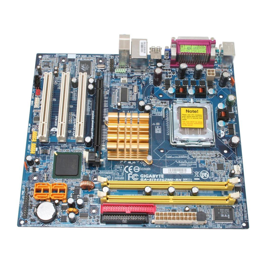
Page 6: Ga-8I945Gmf-Rh Motherboard Layout
GA-8I945GMF-RH Motherboard Layout KB_MS ATX_12V CPU_FAN LGA775 Intel 945G AUDIO1 PCIE_16 AUDIO2 PCI1 Marvell 8053 SATAII2_3 BIOS PCI2 ICH7 BATTERY CD_IN PCIE_1 TSB43AB23 SATAII0_1 CODEC CLR_CMOS SYS_FAN F_USB F1_1394 F2_1394 GREEN_USB SPDIF_IO COMB F_PANEL PWR_LED (Optional) - 6 -... -
Page 7: Block Diagram
Block Diagram CPUCLK+/-(266/200/133MHz) LGA775 PCI-ECLK Processor (100MHz) Host DDRII 667 /533/400MHz DIMM (Note) Interface PCI Express x16 Dual Channel Memory Intel 945G GMCH GMCHCLK (266/200/133MHz) 66MHz 33MHz RJ45 14.318MHz 1 PCI Express x 1 Port 48MHz PCI-ECLK(100MHz) Marvell BIOS 8053 PCI Express Bus 4 Serial ATAII ATA33/66/100... - Page 8 - 8 -...
-
Page 9: Chapter 1 Hardware Installation
2. Damage as a result of violating the conditions recommended in the user manual. 3. Damage due to improper installation. 4. Damage due to use of uncertified components. 5. Damage due to use exceeding the permitted parameters. 6. Product determined to be an unofficial Gigabyte product. - 9 - Hardware Installation... -
Page 10: Feature Summary
1 RJ 45 port Supported on the Win 2000/XP operating systems (Note 1) For further CPU support information, please go to GIGABYTE's website. (Note 2) Due to standard PC architecture, a certain amount of memory is reserved for system usage and therefore the actual memory size is less than the stated amount. - Page 11 Onboard Audio ALC882 CODEC High Definition Audio Supports 2 / 4 / 6 / 8 channel audio Supports Line In ; Line Out (Front Speaker Out) ; MIC ; Surround Speaker Out (Rear Speaker Out) ; Center/Subwoofer Speaker Out ; Side Speaker Out connection SPDIF In/Out connection CD In...
-
Page 12: Installation Of The Cpu And Heatsink
(Grasping the CPU firmly between your thumb and forefinger, carefully place it into the socket in a straight and downwards motion. Avoid twisting or bending motions that might cause damage to the CPU during installation.) GA-8I945GMF-RH Motherboard - 12 -... -
Page 13: Installation Of The Heatsink
1-3-2 Installation of the Heatsink Male Push Pin The top of Female Push Pin Female Push Pin Fig. 2 Fig.1 Please apply an even layer of heatsink paste on (Turning the push pin along the direction of arrow the surface of the installed CPU. is to remove the heatsink, on the contrary, is to install.)Please note the direction of arrow sign on the male push pin doesn't face inwards before... -
Page 14: Installation Of Memory
DIMM socket. Then push it down. Fig.2 Close the plastic clip at both edges of the DIMM sockets to lock the DIMM module. Reverse the installation steps when you wish to remove the DIMM module. GA-8I945GMF-RH Motherboard - 14 -... - Page 15 GA-8I945GMF-RH supports the Dual Channel Technology. After operating the Dual Channel Technology, the bandwidth of Memory Bus will double. GA-8I945GMF-RH includes 4 DIMM sockets, and each Channel has two DIMM sockets as following: Channel A : DDR II 1, DDR II 2...
-
Page 16: Install Expansion Cards
VGA card. Please align the VGA card to the onboard PCI Express x 16 slot and press firmly down on the slot .Make sure your VGA card is locked by the small white-drawable bar. GA-8I945GMF-RH Motherboard - 16 -... -
Page 17: I/O Back Panel Introduction
I/O Back Panel Introduction PS/2 Keyboard and PS/2 Mouse Connector To install a PS/2 port keyboard and mouse, plug the mouse to the upper port (green) and the keyboard o the lower port (purple). Parallel Port The parallel port allows connection of a printer, scanner and other peripheral devices. COM A (Serial Port) Connects to serial-based mouse or data processing devices. -
Page 18: Connectors Introduction
Mic In jack ( ) . Please refer to the 2-/4-/6-/8- channel audio setup steps for detailed software configuration information. Connectors Introduction ATX_12V PWR_LED (Optional) ATX (Power Connector) CD_IN CPU_FAN GREEN_USB/F_USB SYS_FAN F1_1394 / F2_1394 COMB SPDIF_IO SATAII0_1 / SATAII2_3 F_PANEL CLR_CMOS F_AUDIO RF_ID BATTERY GA-8I945GMF-RH Motherboard - 18 -... - Page 19 1/2) ATX_12V/ATX (Power Connector) With the use of the power connector, the power supply can supply enough stable power to all the components on the motherboard. Before connecting the power connector, please make sure that all components and devices are properly installed. Align the power connector with its proper location on the motherboard and connect tightly.
- Page 20 The FDD connector is used to connect the FDD cable while the other end of the cable connects to the FDD drive. The types of FDD drives supported are: 360KB, 720KB, 1.2MB, 1.44MB and 2.88MB. Before attaching the FDD cable, please take note of the foolproof groove in the FDD connector. GA-8I945GMF-RH Motherboard - 20 -...
- Page 21 6) IDE (IDE Connector) An IDE device connects to the computer via an IDE connector. One IDE connector can connect to one IDE cable, and the single IDE cable can then connect to two IDE devices (hard drive or optical drive). If you wish to connect two IDE devices, please set the jumper on one IDE device as Master and the other as Slave (for information on settings, please refer to the instructions located on the IDE device).
-
Page 22: F_Panel (Front Panel Jumper)
Pin 2- Pin 3: NC Pin 4: Data(-) RES (Reset Switch) Open: Normal Close: Reset Hardware System PW (Power Switch) Open: Normal Close: Power On/Off MSG(Message LED/Power/Sleep LED) Pin 1: LED anode(+) Pin 2: LED cathode(-) GA-8I945GMF-RH Motherboard - 22 -... -
Page 23: Front Audio Connector
9) F_AUDIO (Front Audio Connector) This connector supports either HD (High Definition) or AC97 front panel audio module. If you wish to use the front audio function, connect the front panel audio module to this connector. Check the pin assignments carefully while you connect the front panel audio module. Incorrect connection between the module and connector will make the audio device unable to work or even damage it. - Page 24 Pin No. Definition Power Power USB DX- USB Dy- USB DX+ USB Dy+ No Pin (Note) When the standby power is shut down, USB devices (example: optical mouses) will not light on during system power-off. GA-8I945GMF-RH Motherboard - 24 -...
- Page 25 13) F1_1394/F2_1394 (IEEE 1394 Connector) Serial interface standard set by Institute of Electrical and Electronics Engineers, which has features like high speed, highbandwidth and hot plug. Be careful with the polarity of the IEEE1394 connector. Check the pin assignment carefully while you connect the IEEE1394 cable, incorrect connection between the cable and connector will make the device unable to work or even damage it.
- Page 26 No Pin SPDIF SPDIFI 16) CI (Chassis Intrusion, Case Open) This 2-pin connector allows your system to enable or disable the "Case Open" item in BIOS, if the system case begin remove. Pin No. Definition Signal GA-8I945GMF-RH Motherboard - 26 -...
- Page 27 18) RF_ID This connector allows you to connect external devices to use extra function. Check the pin assignments before you connect the external device cable. Please contact your nearest dealer for the optional GIGABYTE external device. Pin No. Definition Power...
- Page 28 4. Plug the power cord in and turn on the computer. Danger of explosion if battery is incorrectly replaced. Replace only with the same or equivalent type recommended by the manufacturer. Dispose of used batteries according to the manufacturer's instructions. GA-8I945GMF-RH Motherboard - 28 -...
-
Page 29: Chapter 2 Bios Setup
BIOS needs to be reset to its original settings. If you wish to upgrade to a new BIOS, either Gigabyte's Q-Flash or @BIOS utility can be used. Q-Flash allows the user to quickly and easily update or backup BIOS without entering the operating system. -
Page 30: The Main Menu (For Example: Bios Ver. : F2)
Optimized Defaults indicates the value of the system parameters which the system would be in best performance configuration. Set Supervisor Password Change, set, or disable password. It allows you to limit access to the system and Setup, or just to Setup. GA-8I945GMF-RH Motherboard - 30 -... - Page 31 Set User Password Change, set, or disable password. It allows you to limit access to the system. Save & Exit Setup Save CMOS value settings to CMOS and exit setup. Exit Without Saving Abandon all CMOS value changes and exit setup. - 31 - BIOS Setup...
-
Page 32: Standard Cmos Features
The day, from 1 to 31 (or the maximum allowed in the month) Year The year, from 1999 through 2098 Time The times format in <hour> <minute> <second>. The time is calculated base on the 24-hour military-time clock. For example, 1 p.m. is 13:00:00. GA-8I945GMF-RH Motherboard - 32 -... - Page 33 IDE Channel 0 Master, Slave IDE HDD Auto-Detection Press "Enter" to select this option for automatic device detection. IDE Channel 0 Master(Slave) IDE Device Setup. You can use one of three methods: Auto Allows BIOS to automatically detect IDE devices during POST(default) None Select this if no IDE devices are used and the system will skip the automatic detection step and allow for faster system start up.
- Page 34 640K for systems with 640K or more memory installed on the motherboard. Extended Memory The BIOS determines how much extended memory is present during the POST. This is the amount of memory located above 1 MB in the CPU's memory address map. GA-8I945GMF-RH Motherboard - 34 -...
-
Page 35: Advanced Bios Features
Advanced BIOS Features CMOS Setup Utility-Copyright (C) 1984-2005 Award Software Advanced BIOS Features Hard Disk Boot Priority [Press Enter] Item Help First Boot Device [Floppy] Menu Level Second Boot Device [Hard Disk] Third Boot Device [CDROM] Select Hard Disk Boot Password Check [Setup] Device Priority... - Page 36 On-Chip Frame Buffer Size Set On-chip frame buffer size to 1MB. Set On-chip frame buffer size to 8MB. (Default value) (Note) This item will show up when you install a processor which supports this function. GA-8I945GMF-RH Motherboard - 36 -...
-
Page 37: Integrated Peripherals
Integrated Peripherals CMOS Setup Utility-Copyright (C) 1984-2004 Award Software Integrated Peripherals On-Chip Primary PCI IDE [Enabled] Item Help On-Chip Secondary PCI IDE [Enabled] Menu Level On-Chip SATA Mode [Auto] x PATA IDE Set to Ch.0 Master/Slave SATA Port 0/2 Set to Ch.2 Master/Slave SATA Port 1/3 Set to Ch.3 Master/Slave... - Page 38 Onboard Parallel port Disabled Disable onboard LPT port. 378/IRQ7 Enable onboard LPT port and address is 378/IRQ7. (Default value) 278/IRQ5 Enable onboard LPT port and address is 278/IRQ5. 3BC/IRQ7 Enable onboard LPT port and address is 3BC/IRQ7. GA-8I945GMF-RH Motherboard - 38 -...
- Page 39 Parallel Port Mode Using Parallel port as Standard Parallel Port. (Default value) Using Parallel port as Enhanced Parallel Port. Using Parallel port as Extended Capabilities Port. ECP+EPP Using Parallel port as ECP & EPP mode. ECP Mode Use DMA Set ECP Mode Use DMA to 3. (Default value) Set ECP Mode Use DMA to 1.
-
Page 40: Power Management Setup
Time (hh: mm: ss) Alarm : (0~23) : (0~59) : (0~59) Power On By Mouse Disabled Disable this function. (Default value) Double Click Double click on PS/2 mouse left button to power on the system. GA-8I945GMF-RH Motherboard - 40 -... - Page 41 Power On By Keyboard Password Enter from 1 to 5 characters to set the Keyboard Power On Password. Disabled Disabled this function. (Default value) Keyboard 98 If your keyboard have "POWER Key" button, you can press the key to power on the system. KB Power ON Password When "Power On by Keyboard"...
-
Page 42: Pnp/Pci Configurations
Auto assign IRQ to PCI 1. (Default value) 3,4,5,7,9,10,11,12,14,15 Set IRQ 3,4,5,7,9,10,11,12,14,15 to PCI 1. PCI 2 IRQ Assignment Auto Auto assign IRQ to PCI 2. (Default value) 3,4,5,7,9,10,11,12,14,15 Set IRQ 3,4,5,7,9,10,11,12,14,15 to PCI 2. GA-8I945GMF-RH Motherboard - 42 -... -
Page 43: Pc Health Status
PC Health Status CMOS Setup Utility-Copyright (C) 1984-2005 Award Software PC Health Status Reset Case Open Status [Disabled] Item Help Case Opened Menu Level Vcore DDRV +3.3V +12V Current System Temperature Current CPU Temperature Current CPU FAN Speed 4687 RPM Current SYSTEM FAN Speed System Warning Temperature [Disabled]... - Page 44 With such CPU fans, selecting PWM will not effectively reduce the fan speed. System Smart FAN Control Disabled Disable this function. Enabled When this function is enabled, System fan will run at different speed depending on System temperature. (Default Value) GA-8I945GMF-RH Motherboard - 44 -...
-
Page 45: Frequency/Voltage Control
Frequency/Voltage Control CMOS Setup Utility-Copyright (C) 1984-2005 Award Software Frequency/Voltage Control CPU Clock Ratio [16X] Item Help System Memory Multiplier [Auto] Menu Level Memory Frequency (Mhz) : Move Enter: Select +/-/PU/PD: Value F10: Save ESC: Exit F1: General Help F5: Previous Values F6: Fail-Save Default F7: Optimized Defaults Incorrect using these features may cause your system broken. -
Page 46: Load Fail-Safe Defaults
Exit Without Saving Frequency/Voltage Control ESC: Quit : Select Item F8: Q-Flash F10: Save & Exit Setup Load Optimized Defaults Selecting this field loads the factory defaults for BIOS and Chipset Features which the system automatically detects. GA-8I945GMF-RH Motherboard - 46 -... -
Page 47: Set Supervisor/User Password
2-10 Set Supervisor/User Password CMOS Setup Utility-Copyright (C) 1984-2005 Award Software Standard CMOS Features Load Fail-Safe Defaults Advanced BIOS Features Load Optimized Defaults Integrated Peripherals Set Supervisor Password Power Management Setup Set User Password PnP/PCI Configurations Save & Exit Setup Enter Password: PC Health Status Exit Without Saving... -
Page 48: Save & Exit Setup
Frequency/Voltage Control ESC: Quit : Select Item F8: Q-Flash F10: Save & Exit Setup Abandon all Data Type "Y" will quit the Setup Utility without saving to RTC CMOS. Type "N" will return to Setup Utility. GA-8I945GMF-RH Motherboard - 48 -... - Page 49 - 49 - BIOS Setup...
- Page 50 GA-8I945GMF-RH Motherboard - 50 -...
-
Page 51: Chapter 3 Install Drivers
Chapter 3 Install Drivers Pictures below are shown in Windows XP. Insert the driver CD-title that came with your motherboard into your CD-ROM drive, the driver CD-title will auto start and show the installation guide. If not, please double click the CD-ROM device icon in "My computer", and execute the Run.exe. -
Page 52: Software Applications
Software Applications This page displays all the tools that Gigabyte developed and some free software, you can choose anyone you want and press "install" to install them. Driver CD Information This page lists the contents of software and drivers in this CD-title. -
Page 53: Hardware Information
Hardware Information This page lists all device you have for this motherboard. Contact Us Please see the last page for details. - 53 - Install Drivers... - Page 54 GA-8I945GMF-RH Motherboard - 54 -...
-
Page 55: Chapter 4 Appendix
Motherboard Intelligent Tweaker (M.I.T.) allows user to access and change BIOS feature settings with relative speed and ease. Through GIGABYTE M.I.T. feature the user is no longer required to switch into different modes within BIOS setup in order to change system settings such as the CPU system bus, memory timings or to enabled Gigabyte's unique C.I.A. -
Page 56: Easytune 5 Introduction
Toggles between Easy and Advance Mode Display screen Display panel of CPU frequency Function display LEDs Shows the current functions status GIGABYTE Logo Log on to GIGABYTE website Help button Display EasyTune 5 Help file Exit or Minimize button Quit or Minimize EasyTune 5 software (Note) EasyTune 5 functions may vary depending on different motherboards. -
Page 57: Xpress Recovery2 Introduction
4-1-2 Xpress Recovery2 Introduction Xpress Recovery2 is designed to provide quick backup and restora- tion of hard disk data. Supporting Microsoft operating systems including Windows XP/2000/NT/98/Me and DOS, and file systems including FAT16, FAT32, and NTFS, Xpress Recovery2 is able to back up data on hard disks on PATA and SATA IDE controllers. - Page 58 3. Xpress Recovery2 is compliant with the GPL regulations. 4. On a few motherboards based on Nvidia chipsets, BIOS update is required for Xpress Recovery2 to correctly identify RAID and SATA IDE mode. Please contact your motherboard manufacturer. GA-8I945GMF-RH Motherboard - 58 -...
-
Page 59: Flash Bios Method Introduction
Updating BIOS with Q-Flash Utility on Dual BIOS Motherboards. Some of Gigabyte motherboards are equipped with dual BIOS. In the BIOS menu of the motherboards supporting Q-Flash and Dual BIOS, the Q-Flash utility and Dual BIOS utility are combined in the same screen. - Page 60 Contains the names of four tasks. Blocking a task and pressing Enter key on your keyboard to enable execu- tion of the task. Action bar: Contains the names of four actions needed to operate the Q-Flash/Dual BIOS utility. Pressing the buttons mentioned on your keyboards to perform these actions. GA-8I945GMF-RH Motherboard - 60 -...
- Page 61 Using the Q-Flash utility: This section tells you how to update BIOS using the Q-Flash utility. As described in the "Before you begin" section above, you must prepare a floppy disk having the BIOS file for your motherboard and insert it to your computer.
- Page 62 Primary Master : FUJITSU MPE3170AT ED-03-08 Primary Slave : None Secondary Master : CREATIVEDVD-RM DVD1242E BC101 Secondary Slave : None Press DEL to enter SETUP / Dual BIOS / Q-Flash / F9 For Xpress Recovery 09/23/2003-i875P-6A79BG03C-00 GA-8I945GMF-RH Motherboard - 62 -...
- Page 63 6. Press Del to enter BIOS menu after system reboots. When you are in BIOS menu, move to Load Optimized Defaults item and press Enter to load BIOS Optimized Defaults. Normally the system redetects all devices after BIOS has been upgraded. Therefore, we highly recommend reloading the BIOS defaults after BIOS has been upgraded.
- Page 64 ESC:Reset F10:Power Off After BIOS file is read, you'll see a confirmation dialog box asking you "Are you sure to update BIOS?" Please do not take out the floppy disk when it begins flashing BIOS. GA-8I945GMF-RH Motherboard - 64 -...
- Page 65 Press Y button on your keyboard after you are sure to update BIOS. Then it will begin to update BIOS. The progress of updating BIOS will be shown at the same time. Q-Flash Utility V1.30 Flash Type/Size.........SST 49LF003A 256K Keep DMI Data Enable Do not trun off power or Updating BIOS Now...
-
Page 66: @Bios Utility
Windows. Just select the desired @BIOS server to download the latest version of BIOS. Fig 1. Installing the @BIOS utility Fig 2. Installation Complete and Run @BIOS Click Sart/ Programs/ GIGABYTE/@BIOS Select @BIOS item than click Install Fig 3. The @BIOS Utility Fig 4. Select the desired @BIOS server Click "... - Page 67 III. In method I, if the BIOS file you need cannot be found in @BIOS server, please go onto Gigabyte's web site for downloading and updating it according to method II. IV. Please note that any interruption during updating will cause system unbooted.
-
Page 68: 4- / 6- / 8- Channel Audio Function Introduction
(you can also find the icon in Control Panel). Double-click the icon to open the Audio Control Panel. STEP 2: In the Audio Control Panel, click the Audio I/O tab. In the upper left list, click 2CH Speaker. GA-8I945GMF-RH Motherboard - 68 -... - Page 69 STEP 3: After a speaker or headphone is plugged into the rear Line Out jack, a small window will pop up and ask you what type of equipment is connected. Choose Headphone or Line Out depending on the device connected and click OK. The 2-chan- nel audio setup is completed.
- Page 70 After installation of the audio driver, you should find an Audio Manager icon in your system tray (you can also find the icon in Control Panel). Double-click the icon to open the Audio Control Panel. GA-8I945GMF-RH Motherboard - 70 -...
- Page 71 STEP 2: In the Audio Control Panel, click the Audio I/O tab. In the upper left list, click 8CH Speaker. STEP 3: After plugging in 8-channel speakers to the rear speaker jacks, a small window will pop up and ask you what type of equipment is connected. Choose a device depending on the type of speaker connected (8-channel audio consists of Front Speaker Out (Line Out), Rear Speaker Out, Cen-...
-
Page 72: Troubleshooting
Below is a collection of general asked questions. To check general asked questions based on a specific motherboard model, please log on to GIGABYTE's website. Question 1: I cannot see some options that were included in previous BIOS after updating BIOS. Why? Answer: Some advanced options are hidden in new BIOS version. - Page 73 - 73 - Appendix...
- Page 74 GA-8I945GMF-RH Motherboard - 74 -...
- Page 75 - 75 - Appendix...
- Page 76 GA-8I945GMF-RH Motherboard - 76 -...
- Page 77 - 77 - Appendix...
- Page 78 GA-8I945GMF-RH Motherboard - 78 -...
- Page 79 Contact Us Taiwan (Headquarters) China GIGA-BYTE TECHNOLOGY CO., LTD. NINGBO G.B.T. TECH. TRADING CO., LTD. Address: No.6, Bau Chiang Road, Hsin-Tien, WEB address : http://www.gigabyte.cn Taipei 231, Taiwan Shanghai TEL: +886-2-8912-4888 TEL: +86-21-63410999 FAX: +886-2-8912-4003 FAX: +86-21-63410100 Tech. and Non-Tech. Support (Sales/Marketing) : Beijing http://ggts.gigabyte.com.tw...
- Page 80 Germany Russia G.B.T. TECHNOLOGY TRADING GMBH Moscow Representative Office Of GIGA-BYTE Technology WEB address : http://www.gigabyte.de Co., Ltd. U.K. WEB address : http://www.gigabyte.ru G.B.T. TECH. CO., LTD. Latvia WEB address : http://www.giga-byte.co.uk GIGA-BYTE Latvia The Netherlands WEB address : http://www.gigabyte.com.lv GIGA-BYTE TECHNOLOGY B.V.