Table of Contents
Advertisement
Quick Links
Advertisement
Table of Contents

Related Manuals for TRENDnet TV-IP422


Summary of Contents for TRENDnet TV-IP422
-
Page 2: Reface
REFACE The Day/Night Pan/Tilt Internet Camera Server with Audio (TV-IP422/TV- IP422W) provides day and night security over a large area. See, hear and talk to people in your camera’s viewing field day or night from any Internet connection. Secure a larger area with pan and tilt Internet cameras. -
Page 3: Table Of Contents
Contents ..................1 R E F A C E 1 .................. 4 H A P T E R ................4 N T R O D U C T I O N 1.1 P ACKAGE ONTENTS ..............4 1.2 G ........5 ETTING TO AMERA 1.3 F... -
Page 4: C H A P T E
5 ................6 2 H A P T E R ™ S ............. 6 2 E C U R I E W O F T W A R E 5.1 INSTALLATION ..............62 5.2 USING INSTALLATION ............67 TEM FEATURES ................ -
Page 5: Introduction
HAPTER NTRODUCTION 1.1 Package Contents The package includes the following: TV-IP422 or TV-IP422W Camera Utility CD-ROM Multi-Language Quick Installation Guide External Antenna (for TV-IP422W only) GPIO Adapter RJ-45 Cable 12V 1.5A Power Adapter (3.5mm) ... -
Page 6: Getting To Know Your Camera
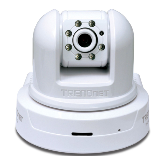
1.2 Getting to Know Your Camera Manual Focus Light Sensor Turn the ring to Antenna is used to trigger on and off adjust the focus the Infrared LEDs according for TV-IP422W only manually the environmental light level. Infrared LEDs allow your camera to capture clear image in a dark environment. -
Page 7: Rear View
External Antenna Connector connects Ethernet Cable Connector the external antenna. connects the network cable, which supports the NWay protocol so that the camera can detect the DC Power Connector network speed connects the AC automatically. power adapter, in order to supply power to the camera. -
Page 8: Features And Benefits
1.3 Features and Benefits MPEG4/MJPEG Dual-codec Supported The camera provides you with excellent images by the MPEG4/ MJPEG dual-codec selectable technology, allowing you to adjust image size and quality, and bit rate according to the networking environment. 2-way Audio Capability ... -
Page 9: System Requirement
device, and then configure the settings and control the device from the GPIO Trigger window of Web Configuration. Remote Control Supported By using a standard Web browser or the bundled SecurView software application, the administrator can easily change the configuration of the camera via Intranet or Internet. - Page 10 Resolution: 800x600 or above User Interface: Microsoft® Internet Explorer 6.0 or above Accessing the Camera using SecurView® Platform: Microsoft® Windows® 2000/XP/Vista Hardware Requirement: 1 camera connected: Intel Pentium III 800MHz; 512MB RAM 2 ~ 4 cameras connected: Intel Pentium 4 1.3GHz; 512MB RAM 5 ~ 8 cameras connected: Intel Pentium 4 2.4GHz;...
-
Page 11: C H A P T E
HAPTER ARDWARE NSTALLATION 2.1 Installing the Wall Mount Kit The camera comes with a Wall Mount Kit, which allows you to place your camera anywhere by mounting the camera through the three screw holes located in the base of the Wall Mount Kit. Screw Wall Mount Kit Screw... -
Page 12: Connecting The Camera To Lan/Wlan
2.2 Connecting the Camera to LAN/WLAN Use the provided Ethernet cable to connect the camera to your local area network (LAN). When you connect the AC power adapter, the camera is powered on automatically. You can verify the power status from the Power LED on the front panel of the camera. -
Page 13: Applications Of The Camera
NOTE If the camera cannot to your wireless network, you need to install the camera in LAN and proceed with WLAN settings. 2.3 Applications of the Camera The camera can be applied in multiple applications, including: Monitor local and remote places and objects via Internet or Intranet. ... -
Page 14: C C E S S I N G H E A M E R
HAPTER CCESSING AMERA 3.1 Using IPSetup The camera comes with a conveniently utility, IPSetup, which is included in the Installation CD-ROM, allowing you to search the camera on your network easily. 1. Insert the Installation CD-ROM into your computer’s CD-ROM drive to initiate the Auto-Run program. - Page 15 3. Click “Browse” to choose the desired destination location. By default, the destination location is C:\Program Files\TRENDnet\IPSetup. Then Click “Next”. - 14 -...
- Page 16 4. Click “Next” to confirm the IPSetup software to be installed to the computer. 5. When the Installation Complete window appears, click “Finish”. - 15 -...
- Page 17 6. After installing the IPSetup utility, the application is automatically installed to your computer, and creates a folder in “ Start \Program\TRENDnet\IPSetup”. 7. Click Start > Programs > TRENDnet > IPSetup, and then click IPSetup 8. The IPSetup window will appear. It will search the Camera within the same network.
- Page 18 Camera Display Area: It shows the connected camera(s) within the same network Double click the IP address, it will link to Camera’s Web Configuration page. Change IP: Click this button to bring up the following window. It allows you to change the IP Address. You can select either Static IP or click DHCP.
-
Page 19: Accessing To The Camera
3.2 Accessing to the Camera 1. Open the Web browser on your computer (example showed in the User’s Guide is based on the Internet Explorer) Type the Camera IP address (For example, if your DHCP server assign is as192.168.10.30) in the web browser URL and then press [Enter]. 3. - Page 20 4. When the login window appears, enter the default User name (admin) and password (admin) and press OK to access to the main screen of the camera’s Web Configuration. NOTE If you are initially access to the camera, you will be ask to install a new plug-in for the camera.
- Page 21 After you login into the Web Configuration of the camera, the main page will appear as below: Zoom In Buttons Nightmode Button Live View/Setup Switch Camera Information Compression Buttons Pan/Tilt Buttons Live View Image Function Buttons The main page of the Web Configuration provides you with many useful information and functions, including: Camera Information Displays the camera’s location and the...
-
Page 22: Chapter 4.
Move your mouse to the Live View area and click on anywhere, the camera lens will then move to the position where you clicked to display it in the central part of Live View area. When you enlarge the Live View by clicking the Zoom In buttons (2x or 3x), you can move the displayed image by right-clicking your mouse on the Live View area. - Page 23 Auto Patrol button controls the camera to automatically scan the preset positions once. Click Stop to stop patrolling. Click the Number button (1~8) to move the camera lens to the preset position immediately. To set up the preset positions, move the camera lens by clicking the Left/Right/Up/Down buttons to the desired position first, then select the number (1~8) from the pull-down list and click the Apply button.
-
Page 24: Configuring The Ip Address Of The Pc
3.3 Configuring the IP Address of the PC If you are failed to access to the camera, please check the IP address of your computer. When you connect the camera to your computer directly to proceed with configuration of the camera, you need to set up the IP addresses to be in the same segment for the two devices to communicate. -
Page 25: Using The Web Configuration
HAPTER ONFIGURING AMERA 4.1 Using the Web Configuration You can access and manage the camera through the Web browser and the provided software application SecurView. This chapter describes the Web Configuration, and guides you through the configuration of the camera by using the Web browser. To configure the camera, click Setup on the main page of Web Configuration. -
Page 26: Using Smart Wizard
4.2 Using Smart Wizard The camera’s Smart Wizard lets you configure your camera easily and quickly. The wizard will guide you through the necessary settings with detailed instructions on each step. To start the wizard, click Smart Wizard in the left menu bar. Step 1. - Page 27 changed to new password, please keep a record. You will need the new password to view or configure the camera later on. Step 2. IP Settings Choose DHCP, Static IP or PPPoE - 26 -...
- Page 28 Step 3. Email Settings Enter mail server information for sending still image to email account. Step 4. Wireless Networking Enter wireless network information - 27 -...
- Page 29 Step 5. Confirm Settings Review your setting. Click Apply to save the setting and reboot the camera. Click <Prev to go back to previous setting. Click Cancel to existing the setting without any changes. - 28 -...
-
Page 30: Basic Setup
4.3 Basic Setup The Basic menu contains three sub-menus that provide the system settings for the camera, such as the Camera Name, Location, Date & Time, and User management. Basic >> System Basic - Camera Name: Enter a descriptive name for the camera. - Location: Enter a descriptive name for the location used by the camera. - Page 31 This item allows you to set the LED illumination as desired. There are two options: Normal and OFF. Basic >> Date & Time - TimeZone: Select the proper time zone for the region from the pull-down menu. - Synchronize with PC: Select this option and the date & time settings of the camera will be synchronized with the connected computer.
- Page 32 - Manual: Select this option to set the date and time manually. Basic >> User Administrator To prevent unauthorized access to the camera’s Web Configuration, you are strongly recommend to change the default administrator password. Type the administrator password twice to set and confirm the password.
- Page 33 - User Name: Enter the user’s name you want to add to use the camera. - Password: Enter the password for the new user. When you are finished, click Add/Modify to add the new user to the camera. To modify the user’s information, select the one you want to modify from UserList and click Add/Modify.
- Page 34 NOTE The “General User” can access the camera and control the Function buttons of the camera’s Web Configuration; the “Guest’ can only view the live view image from the main page of the Web Configuration while accessing the camera. Only the “Administrator”...
-
Page 35: Network Settings
4.4 Network Settings The Network menu contains three sub-menus that provide the network settings for the camera, such as the IP Setting, DDNS Setting, IP Filter, and Wireless network. Network >> Network IP Setting This item allows you to select the IP address mode and set up the related configuration. - Page 36 - DHCP: Select this option when your network uses the DHCP server. When the camera starts up, it will be assigned an IP address from the DHCP server automatically. - Static IP: Select this option to assign the IP address for the camera directly.
- Page 37 UPnP The camera supports UPnP (Universal Plug and Play), which is a set of computer network protocols that enable the device-to-device interoperability. In addition, it supports port auto mapping function so that you can access the camera if it is behind an NAT router or firewall.
- Page 38 Network >> IP Filter The IP Filter setting allows the administrator of the camera to limit the users within a certain range of IP addresses to access the camera. Start/End IP Address Assign a range of IP addresses that are not allowed to access the camera by entering the Start IP address and End IP address.
- Page 39 Deny IP List The list displays the range setting(s) of IP addresses that are not allowed to access the camera. To clear the setting, select a range of IP addresses from the list and click Delete. Network >> Wireless Setting The camera supports WLAN while you use the wireless network.
- Page 40 Click Site Survey to display the available wireless networks, so that you can easily connect to one of the listed wireless networks. - Wireless Mode: Select the type of wireless communication for the camera: Infrastructure or Ad-Hoc. - Channel: Select the appropriate channel from the list. - Authentication: Select the authentication method to secure the camera from being used by unauthorized user: Open, Shared-key, WPA-PSK, and WPA2-PSK.
-
Page 41: Pan/Tilt Settings
Key Length: Select the WEP key length you use: 64 bits or 128 bits. WEP Key 1/2/3/4: Enter the WEP key(s) in the following boxes. If you select WPA-PSK or WPA2-PSK as the Authentication mode, you need to complete the following settings: Encryption: Select TKIP or AES. - Page 42 - Pan/Tilt Calibration: Click Calibration to calibrate the position of the camera lens. - Pan Steps: Set the changing range (1~20 degrees) when you click the Left/Right button. - Tilt Steps: Set the changing range (1~20 degrees) when you click the Up/Down button.
-
Page 43: Setting Up Video & Audio
4.6 Setting up Video & Audio The Video & Audio menu contains three sub-menus that provide the video and audio settings for the camera. Video & Audio >> Camera Image Setting - Brightness: Adjust the brightness level from 0 ~ 100. - Contrast: Adjust the contrast level from 0 ~ 100. - Page 44 - Mirror: Select the Horizontal option to mirror the image horizontally. Select the Vertical option to mirror the image vertically. - Light Frequency: Select the proper frequency according to the camera’s location: 50Hz, 60Hz, or Outdoor. Overlay Setting - Includes Date & Time: Select this option to display the date & time stamp on the live view image.
- Page 45 Video & Audio >> Video MPEG4 - Video Resolution: Select the desired video resolution from the three formats: VGA, QVGA and QQVGA. The higher setting (VGA) obtains better video quality while it uses more resource within your network. - Video Quality: Select the desired image quality from five levels: Lowest, Low, Medium, High, and Highest.
- Page 46 MJPEG - Video Resolution: Select the desired video resolution from the three formats: VGA, QVGA and QQVGA. The higher setting (VGA) obtains better video quality while it uses more resource within your network. - Video Quality: Select the desired image quality from five levels: Lowest, Low, Medium, High, and Highest.
- Page 47 Video & Audio >> Audio Camera Microphone In Select the Enable option to enable the camera’s audio function, so that you can receive the on-site sound and voice from the camera. Camera Speaker Out Select the Enable option to enable the camera’s external speaker function, so that the connected speaker can play the sound and voice through the camera.
-
Page 48: Event Server Configuration
4.7 Event Server Configuration The Event Server menu contains three sub-menus that allow you to upload images to FTP, send emails that include still images, and store the images to a NAS system. When you complete the required settings for FTP, Email, or Network Storage, click Test to test the related configuration is correct or not. - Page 49 - Password: Enter the password to login into the FTP server. - Directory Path: Enter the destination folder for uploading the images. For example, /Test. - Passive Mode: Select the Enable option to enable passive mode. - 48 -...
- Page 50 Event Server Setting >> Email - SMTP Server Address: Enter the mail server address. - Sender Email Address: Enter the email address of the user who will send the email. - Sender User Name: Enter the user name to login the mail server. - Sender Password: Enter the password to login the mail server.
- Page 51 Event Server Setting >> Network Storage - Samba Server Address: Enter the IP address of the Network Storage server. - Share: Assign the folder on the Network Storage server to share the files to users. - Path: Assign the path for uploading the files on the Network Storage server.
-
Page 52: Motion Detect
- When Disk Full: Select Stop Recording or Recycle – Delete Oldest Folder of File when the storage space on the Network Storage server is full. 4.8 Motion Detect The Motion Detect menu contains the command and option that allow you to enable and set up the motion detection feature of the camera. -
Page 53: Event Config
NOTE Sliding the Threshold bar to the right will decrease the sensitivity of motion detection; sliding the Threshold bar to the left will increase the sensitivity of motion detection 4.9 Event Config The Event Config menu contains five sub-menus that provide the commands to configure event profiles. - Page 54 - Network Storage Recording Time Per Event: Limit the recording time while you are using the Network Storage solution. - GPIO Trigger Out Retention Time Per Event: Limit the retention time of the GPIO Trigger Out function. Event Configuration >> Arrange Schedule Profile This sub-menu displays the scheduled profile(s).
- Page 55 - Profile Name: Display the profile name that you select in the Schedule Profiles list. - Weekdays: Select the weekday(s) that you want to separately assign in the schedule profile. The weekday that has been assigned will be displayed with green color. - Time List: Display the time period that you have assigned within the selected weekday.
- Page 56 - Schedule Profile: Select a schedule profile from the pull-down list. - Action: Set the Trigger Out function or select the destination of the captured images: Save Image to USB, Record to Network, Storage, Send Email, or FTP Upload. NOTE Setting the Pre-event/Post-event time for sending email or uploading to FTP may cause the system overloads.
- Page 57 NOTE If the setting value of the Network Storage Recording Time Per Event option in General Setting is longer than the Interval time in Network Storage Schedule, the recorded file will be a continuous video clip. For example, if you set the Network Storage Recording Time Per Event as 10 seconds and the Interval as 5 seconds, recorded file becomes a non-stop video clip because the camera will record a 10-second video clip every 5 seconds.
- Page 58 Storage server, or the connected USB device. You have to configure corresponding settings, such as FTP server and email server, to enable this feature. - Schedule Profile: Select a schedule profile from the pull-down list. - Action: Set the Trigger Out function or select the destination of the captured images: Save Image to USB, Record to Network, Storage, Send Email, or FTP Upload.
-
Page 59: Tools
4.10 Tools The Tools menu provides the commands that allow you to restart or reset the camera. You can also backup and restore your configuration, and upgrade the firmware for the camera. Factory Reset Click Reset to restore all factory default settings for the camera. System Reboot ... - Page 60 You can save your camera configuration as a backup file on your computer. Whenever you want to resume the original settings, you can restore them by retrieving the backup file. - Backup: Click Get the backup file to save the current configuration of the camera.
-
Page 61: Usb
4.11 USB The USB menu provides the information and controls of the connected USB device. USB Dismount To safely remove the connected USB device, you can press the Unmount button for four seconds on the camera or click Dismount from this item. -
Page 62: Information
NOTE The connected USB storage device can be used to store still images only and as your host system backup. It is not recommended to use the USB device as your major storage device. 4.12 Information The Information menu displays the current configuration and events log of the camera. -
Page 63: S E C U R V I E W ™ S O F T W A R
HAPTER ™ S ECUR OFTWARE This Chapter describes detail instructions on operating SecurView™ software, a useful friendly application for ease of control and navigation requirement. INSTALLATION 1. Insert the Installation CD-ROM into your computer’s CD-ROM drive to initiate the Auto-Run program. 2. - Page 64 NOTE To use SecurView™, you must have Microsoft .NET Framework 2.0 installed in the computer. The setup wizard will detect it and, if the program is not installed yet, ask you to install it during the process of installing SecurView™. 3.
- Page 65 4. Click “Browse” to choose the desired destination location. By default, the destination location is C:\Program Files\TRENDnet\SecurView. Then Click “Next”. - 64 -...
- Page 66 5. Click “Next” to confirm the SecurView software to be installed to the computer. - 65 -...
- Page 67 6. Click t When the Installation Complete window appears, click “Close”. - 66 -...
-
Page 68: Using Installation
“ Start \Program\TRENDnet\SecurView”. USING INSTALLATION To launch the program, click Start > Program > TRENDnet > SecurView, and then click SecruView™. The main screen will appear as below. - 67 -... -
Page 69: Item Features
NOTE Please set the resolution to 1024x768 or above on your computer while using SecurView™; otherwise, the displayed main screen may be distorted. Item features The following describes the function of each item on the main screen: CONTROLS Panel - 68 -... - Page 70 - SETTING: Click to enter the Setting screen of SecurView™. Click again to return to the main screen of SecurView™. - PLAY: Click to play the recorded video file using the media player on the computer (for example, Windows Media Player by default). - LOCK: Click to lock the camera controls.
- Page 71 - ALL RECORD: Click to start recording video clips using ALL connected cameras. To stop recording, please click Record button to stop the individual camera. Please note: stop recording only stop the manual recording camera. For schedule recording, please change the setting on configuration. By default, the ID and Password boxes are “blank.”...
- Page 72 VIEW SELECTION Panel - View mode buttons: SecurView™ provides multiple view modes, including 1/4/9/16 windows and Full screen mode. - SCAN: When multiple cameras connected, click this button to display the video views between cameras. Click the Scan button again to stop scanning.
- Page 73 CAMERA Panel - TRIGGER OUT: Click to turn on the trigger out connector of the camera. This button is available only when the connected camera supports the trigger out connector, which is used to control the external device connected to the camera, such as a light. - SNAPSHOT: Click to capture a still image using the selected camera and save the file in the computer.
- Page 74 SYSTEM Panel This panel displays the current date and time. PAN-TILT CONTROL Panel When you connect a pan/tilt camera, the system will detect the camera’s function automatically and the PAN-TILT CONTROL buttons will become functional. Otherwise, these buttons are displayed as gray out buttons.
- Page 75 Video Viewing Window Camera List - Video Viewing Window: This window displays the video view of the selected camera, which can be divided into 4/9/16 windows according to your selection in VIEW SELECTION panel. - Camera List: This list displays the information of the connected camera(s).
-
Page 76: To Add A Camera
To add a camera 1. Click SETTING in the CONTROLS panel to display the Setting screen. 2. Click Add New Camera. - 75 -... - Page 77 3. In the pop-up Add New Camera dialog window, you can: Select the Search tab if you are not sure of the camera’s IP address. Click Search camera to search the available camera within the network. Once the camera is found and is shown in the list, select it and click Add Camera.
- Page 78 4. Enter the User name and Password for the camera, and then click OK. The connected camera will be displayed in the Camera List. 5. Click SETTING to return to the Video View Window. The video view of the selected camera will be displayed now. - 77 -...
-
Page 79: To Remove A Camera
To remove a camera 1. Click SETTING in the CONTROLS panel to display the Setting screen. 2. Select a camera from the list and click Delete Camera. - 78 -... -
Page 80: To Link To The Web Page Of The Camera
Select a camera Delete the camera To link to the Web page of the camera Click SETTING > Camera List > Camera Configuration and then Link web page to launch the Web browser that displays live view image and Web Configuration of the selected camera. - 79 -... -
Page 81: To Record Video
To record video SecurView™ provides three methods to record video clips: one is to click the RECORD/All Record button to record manually; the second is to record by motion detection; the third is to set the recording schedule in Setting > Recording Configuration > Schedule Recording Configuration. - Page 82 Trigger recording by motion detection When the motion detection function of the selected camera is enabled, you can configure the camera to start recording triggered by the motion detected. Click SETTING > Motion Configuration, and then select the Recording option to enable the selected camera to record by motion detection.
- Page 83 Schedule recording Configuration This recording method will work after you have completed the required settings in Schedule Recording Configuration. The recording schedule can be defined by Dates or Days. - Dates: Select the camera from the pull-down list.. - 82 -...
- Page 84 Select a camera Add Schedule - Then, click Add to set the Start/Stop date and time and then click OK to add the recording schedule to the list. - Click Apply to save the settings - 83 -...
- Page 85 - 84 -...
-
Page 86: To Configure The Recording Settings
Days: First, select the camera from the pull-down list and select Days tab. Then, select the weekday from the day buttons and then set the time period. Click Apply to save the settings. To configure the recording settings To configure the recording settings, including the storage folder and storage options, click SETTING >... - Page 87 Recording File Path: To change the destination folder to save the recorded video file, click Browse under the Recording File Path box to assign a new folder. Each Recording File Size: This option allows you to select from 20 ...
-
Page 88: To Playback The Recorded Video
hard disk drive, you can check the available storage space that is displayed in the HDD Free space field. Enable Recycle Recording: Click on the camera number to clear the files when the unreserved space of the hard disk drive is full. To playback the recorded video The recorded video clips are saved in your computer, and can be played using the media player on the computer, such as Windows Media Player. -
Page 89: To Set Up Motion Detection Options
NOTE If your player on the computer don’t have video codec to playback the recorded video. You can download video codec from http://www.xvid.org/downloads.15.0.html to support. To set up motion detection options When the motion detection function of the selected camera is enabled, you can set the Motion Options by selecting Alarm, Recording, Send e- Mail, and Trigger Out under SETTING >... - Page 90 Browse and then selecting your favorite music (*.wav or *.mp3 file) in the computer. Recording: Select this option to enable the camera to record by motion detected. Send Email: Select this option so that the system will be able to ...
-
Page 91: Account
- Mail From: Enter the email address of the user who will send the email. For example, John@mymail.com. - Mail To: Enter the email address of the user who will receive the email. - User Name: Enter the user name to login the mail server. - Password: Enter the password to login the mail server. -
Page 92: Information
Information Click SETTING > About to display the information of the software application. - 91 -... - Page 93 - 92 -...
-
Page 94: Appendix
PPENDIX A.1 Specification Image Sensor Sensor 1/4” color CMOS Resolution 640x480 Video Compression MPEG4/MJPEG Video resolution VGA/QVGA/QQVGA; 30fps max. Audio Input Built-in MIC Output Headphone output jack (Mono) Codec PCM/AMR (AMR is for 3GPP only) User Interface ... - Page 95 Output: close circuit current 70mA AC or 100mA DC maximum, 30 Ohm; open circuit voltage 240V AC or 350V DC maximum LEDs Power LED (amber); Link LED (green) System Hardware Processor ARM9 base 32MB SDRAM 8MB NOR Flash Power DC 12V Communication ...
-
Page 96: Gpio Terminal Application
Operating Environment Temperature - Operation: 0°C ~ 45°C - Storage: -15°C ~ 60°C Humidity - Operation: 20% ~ 85% non-condensing - Storage: 0% ~ 90% non-condensing FCC Class B, CE Class B A.2 GPIO Terminal Application Typically used in association with programming scripts for developing applications for motion detection, event triggering, alarm notification via e-mail, and a variety of external control functions. -
Page 97: Glossary Of Terms
Interface Schematic A.3 Glossary of Terms NUMBERS 10BASE-T 10BASE-T is Ethernet over UTP Category III, IV, or V unshielded twisted-pair media. 100BASE-TX The two-pair twisted-media implementation of 100BASE-T is called 100BASE-TX. ADPCM Adaptive Differential Pulse Code Modulation, a new technology improved from PCM, which encodes analog sounds to digital form. - Page 98 the applet was sent. ASCII American Standard Code For Information Interchange, it is the standard method for encoding characters as 8-bit sequences of binary numbers, allowing a maximum of 256 characters. Address Resolution Protocol. ARP is a protocol that resides at the TCP/IP Internet layer that delivers data on the same network by translating an IP address to a physical address.
- Page 99 static and dynamic IP addresses. This simplifies the task for network administrators because the software keeps track of IP addresses rather than requiring an administrator to manage the task. A new computer can be added to a network without the hassle of manually assigning it a unique IP address.
- Page 100 Firewall Firewall is considered the first line of defense in protecting private information. For better security, data can be encrypted. A system designed to prevent unauthorized access to or from a private network. Firewalls are frequently used to prevent unauthorized Internet users from accessing private networks connected to the Internet, especially Intranets all messages entering or leaving the intranet pass through the firewall, which examines each message and...
- Page 101 Internet address To participate in Internet communications and on Internet Protocol-based networks, a node must have an Internet address that identifies it to the other nodes. All Internet addresses are IP addresses Internet Protocol is the standard that describes the layout of the basic unit of information on the Internet (the packet) and also details the numerical addressing format used to route the information.
- Page 102 MJPEG MJPEG (Motion JPEG) composes a moving image by storing each frame of a moving picture sequence in JPEG compression, and then decompressing and displaying each frame at rapid speed to show the moving picture. MPEG4 MPEG4 is designed to enable transmission and reception of high-quality audio and video over the Internet and next- generation mobile telephones.
- Page 103 PCM (Pulse Code Modulation) is a technique for converting analog audio signals into digital form for transmission. PING Packet Internet Groper, a utility used to determine whether a specific IP address is accessible. It functions by sending a packet to the specified address and waits for a reply. It is primarily used to troubleshoot Internet connections.
- Page 104 RJ-45 RJ-45 connector is used for Ethernet cable connections. Router A router is the network software or hardware entity charged with routing packets between networks. RTP (Real-time Transport Protocol) is a data transfer protocol defined to deliver live media to the clients at the same time, which defines the transmission of video and audio files in real time for Internet applications.
- Page 105 various transmission methods. It was developed y the Department of Defense to connect different computer types and led to the development of the Internet. Transceiver A transceiver joins two network segments together. Transceivers can also be used to join a segment that uses one medium to a segment that uses a different medium.
- Page 106 (TKIP), to secure data during transmission. WPA2 Wi-Fi Protected Access 2, the latest security specification that provides greater data protection and network access control for Wi-Fi networks. WPA2 uses the government-grade AES encryption algorithm and IEEE 802.1X-based authentication, which are required to secure large corporate networks. - 105 -...
-
Page 107: Limited Warranty
The repair/replacement unit’s warranty continues from the original date of purchase. All products that are replaced become the property of TRENDnet. Replacement products may be new or reconditioned. TRENDnet does not issue refunds or credit. Please contact the point-of-purchase for their return policies. - Page 108 (RMA) number will be issued. An RMA number is required in order to initiate warranty service support for all TRENDnet products. Products that are sent to TRENDnet for RMA service must have the RMA number marked on the outside of return packages and sent to TRENDnet prepaid, insured and packaged appropriately for safe shipment.
- Page 109 ANY OTHER PERSON TO ASSUME FOR IT ANY OTHER LIABILITY IN CONNECTION WITH THE SALE, INSTALLATION MAINTENANCE OR USE OF TRENDNET’S PRODUCTS. TRENDNET SHALL NOT BE LIABLE UNDER THIS WARRANTY IF ITS TESTING AND EXAMINATION DISCLOSE THAT THE ALLEGED DEFECT IN THE PRODUCT DOES NOT EXIST OR WAS CAUSED BY CUSTOMER’S OR ANY THIRD PERSON’S MISUSE, NEGLECT,...
- Page 110 Download section and look for the desired TRENDnet product to access to the GPL Code or LGPL Code. These codes are distributed WITHOUT WARRANTY and are subject to the copyrights of the developers. TRENDnet does not provide technical support for these codes. Please go http://www.gnu.org/licenses/gpl.txt...
- Page 111 - 110 -...