
Related Manuals for Dell XPS 720


Summary of Contents for Dell XPS 720
- Page 1 Dell™ XPS™ 720 Owner’s Manual Model DCDO w w w . d e l l . c o m | s u p p o r t . d e l l . c o m...
- Page 2 Trademarks used in this text: Dell, the DELL logo, XPS, H2C, Inspiron, Dell Precision, Dimension, OptiPlex, Latitude, PowerEdge, PowerVault, PowerApp, TravelLite, Strike Zone, and Dell OpenManage are trademarks of Dell Inc.; Intel, Pentium, Celeron, and Intel Core 2 Extreme are either trademarks or registered trademarks of Intel Corporation;...
-
Page 3: Table Of Contents
Contents Finding Information ....... . Setting Up and Using Your Computer . - Page 4 ......Dell™ QuickSet ......
- Page 5 Starting Dell Diagnostics From Your Hard Drive ....Starting Dell Diagnostics From the Drivers and Utilities Media ..Dell Diagnostics Main Menu .
- Page 6 Cards ........Removing PCI and PCI Express Cards .
- Page 7 Removing the Optional Hard Drive Fan ....Installing the Optional Hard Drive Fan ....System Board .
- Page 8 ..... . Contacting Dell ....... . .
-
Page 9: Finding Information
You can use the Drivers and Utilities media to reinstall drivers (see "Reinstalling Drivers and Utilities" on • Desktop System Software (DSS) page 76), access your documentation or run the Dell Diagnostics (see "Dell Diagnostics" on page 72). Readme files may also be... - Page 10 Product Key Label These labels are located on your computer. • Use the Service Tag to identify your computer when you use support.dell.com or contact support. • Enter the Express Service Code to direct your call when contacting support. Finding Information...
- Page 11 Select Drivers & Downloads, and then click Go. appropriate for your configuration, providing critical Select your operating system and language, and then updates for your operating system and support for Dell™ search for the keyword Desktop System Software. ® ®...
- Page 12 What Are You Looking For? Find It Here • How to reinstall my operating system Operating System Media The operating system is already installed on your computer. To reinstall your operating system, use the Operating System media. After you reinstall the operating system, use the Drivers and Utilities media to reinstall drivers for the...
-
Page 13: Setting Up And Using Your Computer
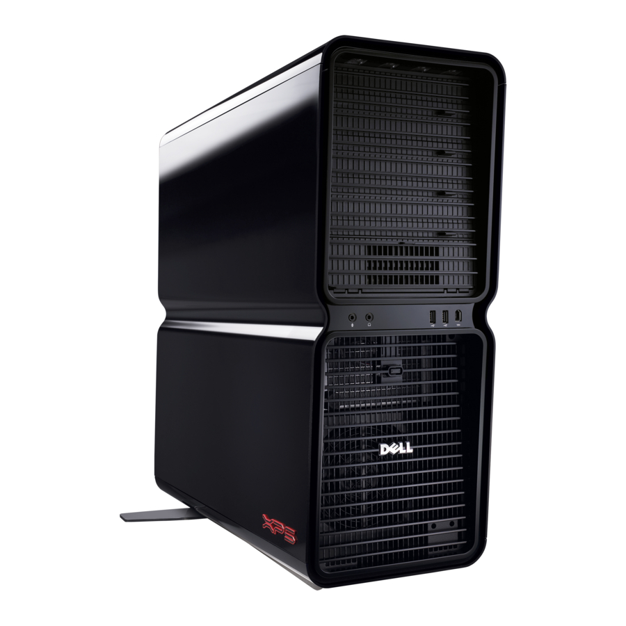
Setting Up and Using Your Computer Front and Back View of the Computer Front View Setting Up and Using Your Computer... - Page 14 LEDs (4) Use the sequence of these diagnostics lights to help troubleshoot a problem with your computer (see "Dell Diagnostics" on page 72). NOTE: The color of the front panel LEDs can be adjusted in system setup (see "System Setup"...
-
Page 15: Front I/O Connectors
USB devices. For more information on bootable USB devices see "Boot Sequence" on page 175. Dell recommends that you use the back USB connectors for devices that typically remain connected, such as printers and keyboards. -
Page 16: Back View
Back View power connector Insert the power cable. The appearance of this connector may differ from what is pictured. back panel LEDs (2) Multi-colored lights provide illumination for the I/O panel on the back of the computer. NOTE: The color of the back panel LEDs can be adjusted in system setup (see "System Setup"... -
Page 17: Back I/O Connectors
(such as a separate intra- and extranet). NOTE: Dell recommends that you use Category 5 wiring and connectors for your network. If you must use Category 3 wiring, force the network speed to 10 Mbps to ensure reliable operation. -
Page 18: Attaching The Computer Stand
Use the back USB connectors for devices that typically remain connected, such as printers and keyboards. NOTE: Dell recommends that you use the front USB connectors for devices that you connect occasionally, such as flash memory keys, cameras, or bootable USB devices. IEEE 1394 connector Use the IEEE 1394 connector for high-speed data devices such as digital video cameras and external storage devices. - Page 19 CAUTION: The computer stand should be installed at all times to ensure maximum system stability. Failure to install the stand could result in the computer tipping over, potentially resulting in bodily injury or damage to the computer. 1 Follow the procedures in "Before You Begin" on page 85. 2 Remove the thumb screw that is installed on the base of the computer.
-
Page 20: Installing Your Computer In An Enclosure
Installing Your Computer in an Enclosure Installing your computer in an enclosure can restrict the airflow and impact your computer’s performance, possibly causing it to overheat. Follow the guidelines below when installing your computer in an enclosure: NOTICE: The operating temperature specifications indicated in your Owner’s Manual reflect the maximum ambient operating temperature. - Page 21 • If your computer is installed in a corner on a desk or under a desk, leave at least 5.1 centimeters (2 inch) of clearance from the back of the computer to the wall to permit the airflow required for proper ventilation.
-
Page 22: Connecting Monitors
• Do not install your computer in an enclosure that does not allow airflow. Restricting the airflow impacts your computer’s performance, possibly causing it to overheat. Connecting Monitors CAUTION: Before you perform any of the procedures in this section, follow the safety instructions in the Product Information Guide. -
Page 23: Connecting A Monitor (Without An Adapter)
DVI (white) connector TV-OUT connector VGA (blue) connector Connecting a Monitor (Without an Adapter) CAUTION: Before you perform any of the procedures in this section, follow the safety instructions in the Product Information Guide. NOTE: If your monitor has a VGA connector and your computer does not have a VGA port, follow the instructions in "Connecting a Monitor (With an Adapter)"... -
Page 24: Connecting A Monitor (With An Adapter)
4 Connect the DVI or VGA connector of your monitor to the appropriate connector on the back of the computer: To connect a monitor with a DVI connector, use the (white) DVI port on your computer. To connect a monitor with a VGA connector, use the (blue) VGA port on your computer. Connecting a Monitor (With an Adapter) CAUTION: Before you perform any of the procedures in this section, follow the safety instructions in the Product... -
Page 25: Connecting A Monitor In A Dual Graphics Card Configuration
DVI (white) connector DVI-to-VGA adapter (optional) TV-OUT connector Connecting a Monitor in a Dual Graphics Card Configuration CAUTION: Before you perform any of the procedures in this section, follow the safety instructions in the Product Information Guide. Dual graphics card configurations with multi-GPU technology enabled support only a single monitor. The monitor must be connected to the primary graphics card in order to function. - Page 26 primary video card 1 Save and close all open files and exit all open programs. 2 Shut down the operating system: → → • In Windows XP, click Start Turn Off Computer Turn off. • In Windows Vista, click Start , click the arrow in the lower-right corner of the Start menu as shown below, and then click Shut Down.
-
Page 27: Connecting Two Or More Monitors
Connecting Two or More Monitors CAUTION: Before you perform any of the procedures in this section, follow the safety instructions in the Product Information Guide. NOTE: In order to connect and use two or more monitors in a dual graphics card configuration, multi-GPU technology must be disabled. -
Page 28: Changing The Display Settings To Support Two Or More Monitors
To connect a TV to your computer, an S-video cable is required. If you do not have an S-video cable, you may purchase one at most consumer electronics stores. An S-video cable is not included with your computer. 1 Save and close all open files and exit all open programs. 2 Shut down the operating system: →... -
Page 29: About Your Raid Configuration
About Your RAID Configuration NOTICE: In order to use the migrating option to convert a RAID configuration without losing data, your hard drive must initially be set up as a single drive RAID 0 array before the operating system is loaded onto the drive (see "Using the NVIDIA MediaShield ROM Utility"... -
Page 30: Raid Level 1 Configuration
Another advantage of a RAID level 0 configuration is that it utilizes the full storage capacities of the drives. For example, two 120-GB hard drives combine to provide 240 GB of hard drive space on which to store data. NOTE: In a RAID level 0 configuration, the size of the configuration is equal to the size of the smallest drive multiplied by the number of drives in the configuration. - Page 31 If a drive failure occurs, subsequent read and write operations are directed to the other surviving drives. A replacement drive can then be rebuilt using the data from the surviving drives. Also, because data is duplicated on the primary and additional drives, four 120-GB RAID level 1 drives collectively have a maximum of 240-GB on which to store data.
-
Page 32: Raid Level 5 Configuration
RAID Level 5 Configuration RAID level 5 also uses data parity. RAID level 5 stripes both data and parity information across three or more drives. It provides data striping at the byte level and also stripe error correction information (rotating parity array). This results in excellent performance and good fault tolerance. RAID level 5 is one of the most popular implementations of RAID. -
Page 33: Setting Your Computer To Raid-Enabled Mode
Setting Your Computer to RAID-Enabled Mode 1 Enter system setup (see "Entering System Setup" on page 168). 2 Press the up- and down-arrow keys to highlight Drives, then press <Enter>. 3 Press the up- and down-arrow keys to highlight the applicable SATA drive, then press <Enter>. 4 Press the left- and right-arrow keys to highlight RAID On, and then press <Enter>. -
Page 34: Using Nvidia Mediashield
6 Use the up- and down-arrow keys to select a hard drive to include in the RAID array and then use the right-arrow key to move the selected drive from the Free Disks field to the Array Disks field. Repeat for each disk you want to include in the RAID array. - Page 35 5 Click Custom, then click Next. 6 Use the drop-down box to select Striping (RAID 0), Mirroring (RAID 1), Stripe Mirroring (RAID 0+1), or RAID 5. 7 Click Next. The Free Disk Selection window appears. NOTE: Only RAID-enabled hard drives are listed as free disks. 8 Click to select the drives that will make up the RAID configuration, click Next, and then click Next again.
- Page 36 NVIDIA MediaShield utilizes a one-step process known as migrating to change the current state of a disk or array without losing any data. If needed, additional hard drives can be added to an existing array, including a single-drive RAID 0 configuration for conversion to a two-drive RAID 0 configuration; however, the capacity of the resulting array must be equal to or greater than the size of the original configuration.
-
Page 37: Using Multimedia
4 Click Next. 5 Select the hard drive you want to rebuild by clicking the checkbox beside it. 6 Click Next. 7 Click Finish. The MediaShield RAID management utility window appears and displays the status of the rebuild process. NOTE: You can use your computer while the computer is rebuilding the array. -
Page 38: Copying Cd, Dvd, And Blu-Ray Disc™ (Bd) Media
Ensure that you observe all copyright laws when copying media. NOTE: The types of optical drives offered by Dell may vary by country. The following instructions explain how to make a copy of a CD, DVD, or BD using Roxio Creator. You can also use Roxio Creator for other purposes, such as creating music CDs from audio files stored on your computer or backing up important data. - Page 39 The DVD drives and BD drives installed in Dell computers do not support HD-DVD media. For a list of supported media formats, see "Using Blank CD, DVD, and BD Media" on page 39. How to Copy a CD, DVD, or BD NOTE: BD media can only be copied to other BD media.
-
Page 40: Helpful Tips
DVD-Writable Drives Media Type Read Write Rewritable CD-R CD-RW DVD+R DVD-R DVD+RW DVD-RW DVD+R DL DVD-R DL DVD-RAM BD-Writable Drives Media Type Read Write Rewritable CD-R CD-RW DVD+R DVD-R DVD+RW DVD-RW DVD+R DL DVD-R DL DVD-RAM BD-R BD-RE Helpful Tips •... -
Page 41: Using A Media Card Reader (Optional)
• Use CD-Rs to burn music CDs that you want to play in regular stereos. CD-RWs do not play in most home or car stereos. • Music MP3 files can be played only on MP3 players or on computers that have MP3 software installed. •... -
Page 42: Network Setup Wizard
xD-Picture card and Memory Stick (MS/MS Secure Digital card SmartMedia Card (SMC) Pro/MS Duo/MS Pro Duo) (SD/miniSD)/MultiMedia-Card (MMC/RS-MMC) CompactFlash card Type I and II (CF I/II) and MicroDrive card 1 Inspect the media card to determine the proper orientation for insertion. 2 Slide the media card into the appropriate slot of the media card reader until it is completely seated in the connector. -
Page 43: Transferring Information To A New Computer
Windows XP: 1 Click Start, point to All Programs→ Accessories→ Communications, and then click Network Setup Wizard. 2 On the welcome screen, click Next. 3 Click Checklist for creating a network. NOTE: Selecting the connection method This computer connects directly to the Internet enables the integrated firewall provided with Windows XP SP1. -
Page 44: Power Management Options In Windows Xp
6 On the Select a transfer method screen, click the transfer method of your preference. 7 On the What do you want to transfer? screen, select the items you want to transfer, then click Next. After the information has been copied, the Completing the Collection Phase screen appears. 8 Click Finish. -
Page 45: Hibernate Mode
Because hibernate mode requires a special file on your hard drive with enough disk space to store the contents of the computer memory, Dell creates an appropriately sized hibernate mode file before shipping the computer to you. If the computer’s hard drive becomes corrupted, Windows XP recreates the hibernate file automatically. - Page 46 Power Schemes Tab Each standard power setting is called a scheme. If you want to select one of the standard Windows schemes installed on your computer, choose a scheme from the Power schemes drop-down menu. The settings for each scheme appear in the fields below the scheme name. Each scheme has different settings for starting standby mode, hibernate mode, turning off the monitor, and turning off the hard drive.
-
Page 47: Power Management Options In Windows Vista
Power Management Options in Windows Vista The Microsoft Vista power management features can reduce the amount of electricity your computer uses when it is on and you are not using it. You can reduce power to just the monitor or the hard drive, or you can use sleep mode or hibernate mode to reduce power to the entire computer. - Page 48 Setting Up and Using Your Computer...
-
Page 49: Optimizing For Greater Performance
This may cause system instability and reduce the operating life of your system components. NOTICE: Dell Technical Support will verify the full functionality of the CPU at the factory default setting and support the CPU performance settings available within the system BIOS. Dell does not provide technical support for any hardware or software issues arising from any third party applications used to enable overclocking, such as NVIDIA nTune 5.0. - Page 50 Optimizing for Greater Performance...
-
Page 51: Dell™ Quickset
NOTE: This feature may not be available on your computer. Dell™ QuickSet allows you to select and adjust LED light effects, also known as LightFX™. You can start QuickSet by either clicking, double-clicking, or right-clicking the QuickSet icon in the ®... - Page 52 Dell™ QuickSet...
-
Page 53: Troubleshooting
— If you have to repeatedly reset time and date information after turning on the computer, or if an incorrect time or date displays during start-up, replace the battery (see "Replacing the Battery" on page 158). If the battery still does not work properly, contact Dell (see "Contacting Dell" on page 181). - Page 54 U N T H E E L L I A G N O S T I C S — See "Dell Diagnostics" on page 72. Optical drive problems NOTE: High-speed optical drive vibration is normal and may cause noise, which does not indicate a defect in the drive or the media.
-
Page 55: E-Mail, Modem, And Internet Problems
Click Properties→ Tools→ Check Now. The User Account Control window may appear. If you are an administrator on the computer, click Continue; otherwise, contact your administrator to continue the desired action. Follow the instructions on the screen. E-Mail, Modem, and Internet Problems CAUTION: Before you begin any of the procedures in this section, follow the safety instructions in the Product Information Guide. -
Page 56: Error Messages
E R I F Y T H A T T H E M O D E M I S C O M M U N I C A T I N G W I T H I N D O W S —... -
Page 57: Ieee 1394 Device Problems
If so, run the program that you want to use first. P E R A T I N G S YS T E M N O T F O U N D — Contact Dell (see "Contacting Dell" on page 181). IEEE 1394 Device Problems... -
Page 58: Lockups And Software Problems
Lockups and Software Problems CAUTION: Before you begin any of the procedures in this section, follow the safety instructions in the Product Information Guide. The computer does not start up " on page 66 H E C K T H E D I A G N O S T I C L I G H T S —... -
Page 59: Memory Problems
• Run the Dell Diagnostics (see "Dell Diagnostics" on page 72). F Y O U E X P E R I E N C E O T H E R M E M O R Y P R O B L E M S —... -
Page 60: Mouse Problems
Mouse Problems CAUTION: Before you begin any of the procedures in this section, follow the safety instructions in the Product Information Guide. H E C K T H E M O U S E C A B L E — •... -
Page 61: Power Problems
Power Problems CAUTION: Before you begin any of the procedures in this section, follow the safety instructions in the Product Information Guide. F T H E P O W E R L I G H T I S G R E E N A N D T H E C O M P U T E R I S N O T R E S P O N D I N G —... -
Page 62: Scanner Problems
N S U R E T H A T T H E P R I N T E R I S T U R N E D O N H E C K T H E P R I N T E R C A B L E C O N N E C T I O N S —... -
Page 63: Sound And Speaker Problems
If your computer came with a PCI graphics card installed, removal of the card is not necessary when installing additional graphics cards; however, the card is required for troubleshooting purposes. If you remove the card, store it in a safe and secure location. For information about your graphics card, go to support.dell.com. The screen is blank NOTE: For troubleshooting procedures, see the monitor’s documentation. - Page 64 The screen is difficult to read H E C K T H E M O N I T O R C A B L E C O N N E C T I O N — • Ensure that the monitor cable is connected to the correct graphics card (for dual graphics card configurations). DVI-to-VGA •...
-
Page 65: Power Lights
Power Lights CAUTION: Before you begin any of the procedures in this section, follow the safety instructions in the Product Information Guide. The power button light located on the front of the computer illuminates and blinks or remains solid to indicate different states: •... -
Page 66: Diagnostic Lights
• Plug the computer into a working electrical possible pre-BIOS failure has occurred. outlet (see "Power Problems" on page 61). • If the problem persists, contact Dell (see The diagnostic lights are not lit after the "Contacting Dell" on page 181). - Page 67 • If available, install working memory of the same type into your computer (see "Installing Memory" on page 92). • If the problem persists, contact Dell (see "Contacting Dell" on page 181). Memory modules are detected, but a memory • Ensure that no special requirements for...
- Page 68 (such as the floppy drive or optical drive), check system setup (see "System Setup" on page 168) to ensure the boot sequence is correct for the devices installed on your computer. • If the problem persists, contact Dell (see "Contacting Dell" on page 181). Troubleshooting...
-
Page 69: Beep Codes
1-3-1 through 2-4-4 Memory not being properly identified or used 4-3-1 Memory failure above address 0FFFFh If you experience any of the following beep code errors, see "Contacting Dell" on page 181 for instructions on obtaining technical assistance. Code Cause... -
Page 70: System Messages
Drive" on page 108) and defined correctly in the system setup program (see "System Setup" on page 168). The cache memory is not See "Contacting Dell" on page 181 for Cache Memory Bad, operating. instructions on obtaining technical Do Not Enable assistance. - Page 71 Message Possible Cause Corrective Action An error is occurring on the See "Contacting Dell" on page 181 for CH-2 Timer Error timer on the system board. instructions on obtaining technical assistance. The system configuration Enter the system setup program (see...
-
Page 72: Dell Diagnostics
<F12> in even intervals to open the Boot Device Menu. NOTE: If at any time a message appears stating that no diagnostics utility partition has been found, run Dell (see "Starting Dell Diagnostics From the Drivers and... -
Page 73: Starting Dell Diagnostics From The Drivers And Utilities Media
4 At the Dell Diagnostics Main Menu, left-click with the mouse, or press <Tab> and then <Enter>, to select the test you want to run (see "Dell Diagnostics Main Menu" on page 74). NOTE: Write down any error codes and problem descriptions exactly as they appear and follow the instructions on the screen. -
Page 74: Dell Diagnostics Main Menu
181). NOTE: The Service Tag for your computer is located at the top of each test screen. When contacting Dell support, have your Service Tag ready. The following tabs provide additional information for tests run from the Custom Test or Symptom Tree... -
Page 75: Drivers
A driver acts like a translator between the device and any other programs that use the device. Each device has its own set of specialized commands that only its driver recognizes. Dell ships your computer to you with required drivers already installed—no further installation or configuration is needed. -
Page 76: Reinstalling Drivers And Utilities
Reinstalling Drivers and Utilities NOTICE: The Dell Support website at support.dell.com and your Drivers and Utilities media provide approved drivers for Dell™ computers. If you install drivers obtained from other sources, your computer might not work correctly. Using Windows Device Driver Rollback If a problem occurs on your computer after you install or update a driver, use Windows Device Driver Rollback to replace the driver with the previously installed version. - Page 77 4 When you see the Windows desktop, reinsert the Drivers and Utilities media. 5 At the Welcome Dell System Owner screen, click Next. NOTE: The Drivers and Utilities media displays drivers only for hardware that came installed in your computer. If you installed additional hardware, the drivers for the new hardware might not be displayed by the Drivers and Utilities media.
-
Page 78: Restoring Your Operating System
Both permanently delete all data on the hard drive and remove any programs installed after you received the computer. Use Dell PC Restore or Dell Factory Image Restore only if System Restore did not resolve your operating system problem. -
Page 79: Using Dell Pc Restore And Dell Factory Image Restore
If possible, back up the data before using these options. Use PC Restore or Dell Factory Image Restore only if System Restore did not resolve your operating system problem. - Page 80 NOTICE: Removing Dell PC Restore from the hard drive permanently deletes the PC Restore utility from your computer. After you have removed Dell PC Restore, you will not be able to use it to restore your computer operating system. Troubleshooting...
- Page 81 Dell PC Restore enables you to restore your hard drive to the operating state it was in when you purchased your computer. It is recommended that you do not remove PC Restore from your computer, even to gain additional hard-drive space. If you remove PC Restore from the hard drive, you cannot ever recall it, and you will never be able to use PC Restore to return your computer operating system to its original state.
-
Page 82: Using The Operating System Media
Therefore, do not reinstall Windows XP unless a Dell technical support representative instructs you to do so. 1 Save and close any open files and exit any open programs. -
Page 83: Troubleshooting Software And Hardware Problems
NOTE: The next steps change the boot sequence for one time only. On the next start-up, the computer boots according to the devices specified in the system setup program. 5 When the boot device list appears, highlight CD/DVD/CD-RW Drive and press <Enter>. 6 Press any key to Boot from CD-ROM. - Page 84 Troubleshooting...
-
Page 85: Removing And Installing Parts
In the event of a coolant leak, shut down your system immediately. Unplug your system from the power outlet and contact Dell Technical Support. In the event of skin contact with the coolant, wash your skin with soap and water. Seek medical attention if irritation develops. In the event of eye contact with the coolant, rinse your eyes immediately with water, with your eyelids open, for 15 minutes. -
Page 86: Removing The Computer Cover
NOTICE: To avoid electrostatic discharge and damage to internal components, ground yourself by using a wrist grounding strap or by periodically touching an unpainted metal surface on the computer chassis. NOTICE: Handle components and cards with care. Do not touch the components or contacts on a card. Instead, hold a card by its edges or by its metal mounting bracket. - Page 87 NOTICE: To avoid electrostatic discharge and damage to internal components, ground yourself by using a wrist grounding strap or by periodically touching an unpainted metal surface on the computer chassis. 1 Follow the procedures in "Before You Begin" on page 85. 2 Pull back on the cover release latch.
-
Page 88: Inside View Of Your Computer
Inside View of Your Computer optical drive bays (4) floppy drive/media card hard drive bays (4) reader card fan liquid cooling assembly Removing and Installing Parts... -
Page 89: System Board Components
System Board Components white memory module black memory module hard drive fan connector connectors (DIMM_1-2) connectors (DIMM_3-4) (FAN_HDD) IDE drive connector (IDE) front I/O panel connector back LED connector (FRONTPANEL) power button (PWR_BT) FlexBay connector (INT_USB) main power connector (POWER1) 10 SATA connectors (SATA0-5) front USB connector front panel 1394 connector... -
Page 90: Memory
13 PCI-Express x1 card slot PCI-Express x16 card slot PCI card slot (SLOT3) (SLOT1) (SLOT2) This slot is not available in the This slot is not available in the dual-graphics or double- dual-graphics configuration width, single graphics configuration. 16 PCI-Express x16 card slot PCI card slot (SLOT5) PCI card slot (SLOT6) (SLOT4) -
Page 91: Addressing Memory Configurations
If you remove your original memory modules from the computer during a memory upgrade, keep them separate from any new modules that you may have, even if you purchased the new modules from Dell. If possible, do not pair an original memory module with a new memory module. Otherwise, your computer may not start properly. -
Page 92: Installing Memory
Installing Memory CAUTION: Before you begin any of the procedures in this section, follow the safety instructions in the Product Information Guide. NOTICE: To avoid electrostatic discharge and damage to internal components, ground yourself by using a wrist grounding strap or by periodically touching an unpainted metal surface on the computer chassis. 1 Follow the procedures in "Before You Begin"... -
Page 93: Removing Memory
NOTICE: To avoid damage to the memory module, press the module straight down into the connector while you apply equal force to each end of the module. 5 Insert the module into the connector until the module snaps into position. If you insert the module correctly, the securing clips snap into the cutouts at each end of the module. -
Page 94: Cards
Cards CAUTION: Before you begin any of the procedures in this section, follow the safety instructions in the Product Information Guide. Your computer provides the following slots for PCI and PCI Express cards: • Three PCI card slots • Two PCI Express x16 card slots (can be used in a dual-graphics configuration) •... -
Page 95: Removing Pci And Pci Express Cards
Removing PCI and PCI Express Cards NOTICE: To avoid electrostatic discharge and damage to internal components, ground yourself by using a wrist grounding strap or by periodically touching an unpainted metal surface on the computer chassis. NOTICE: If your computer came with a PCI graphics card installed, removal of the card is not necessary when installing additional graphics cards;... - Page 96 6 Press the release tab (if present) on the system board connector as you grasp the card by its top corners, and then ease the card out of the connector. NOTE: If the card is full length, press the release tab on the end of the alignment guides on the fan bracket. PCI Express x16 card securing tab PCI Express x16 card slot...
-
Page 97: Installing Pci And Pci Express Cards
Installing PCI and PCI Express Cards NOTICE: To avoid electrostatic discharge and damage to internal components, ground yourself by using a wrist grounding strap or by periodically touching an unpainted metal surface on the computer chassis. NOTICE: If your computer came with a PCI graphics card installed, removal of the card is not necessary when installing additional graphics cards;... - Page 98 5 Remove the filler bracket or existing card (see "Removing PCI and PCI Express Cards" on page 95) to create a card-slot opening. 6 Prepare the card for installation. See the documentation that came with the card for information on configuring the card, making internal connections, or otherwise customizing it for your computer.
- Page 99 card connector (seated) card connector (not seated) bracket properly aligned within slot bracket improperly aligned alignment bar alignment guide outside of slot NOTICE: Do not route card cables over or behind the cards. Cables routed over the cards can prevent the computer cover from closing properly or cause damage to the equipment.
-
Page 100: Removing A Pci Express Graphics Card From A Dual Configuration
13 Install any drivers required for the card as described in the card documentation. NOTE: If you installed a sound card or a network adapter, see "Network Adapter and Sound Card Settings" on page 105. Removing a PCI Express Graphics Card from a Dual Configuration NOTE: This section regards dual configurations of PCI Express x16 graphics cards only. - Page 101 5 Disconnect any cables connected to the card. 6 Press down the tab on the top of the card retainer at the appropriate card slot and pivot the card retainer back through the chassis wall. release tab card retainer alignment guide fan bracket 7 Press the release tab (if present) on the system board connector as you grasp the card by its top corners, and then ease the card out of the connector.
-
Page 102: Installing A Pci Express Graphics Card In A Dual Configuration
To upgrade to or downgrade from a dual-graphics configuration, you will need additional parts that can be ordered from Dell (see "Contacting Dell" on page 181). This section pertains to dual PCI Express graphics card configurations only. For installation of other types of PCI or PCI Express cards, see "Installing PCI and PCI Express Cards"... - Page 103 NOTICE: For information about upgrading your system to use NVIDIA SLI (Scalable Link Interface) dual-graphics technology, see the Dell website at support.dell.com. To learn more about NVIDIA SLI (Scalable Link Interface) dual graphics technology, see "Understanding Dual-Graphics Technology" on page 49.
- Page 104 5 Remove the filler bracket or existing graphics card (see "Removing a PCI Express Graphics Card from a Dual Configuration" on page 100) to create a card-slot opening. NOTE: If you are upgrading to a dual graphics card configuration and have a card installed in the PCI Express x1 card slot, remove the card (see "Removing PCI and PCI Express Cards"...
-
Page 105: Network Adapter And Sound Card Settings
graphics card bridge (not power connectors (2) dual-PCI Express graphics present on some dual graphics cards card configurations) NOTICE: To connect a network cable, first plug the cable into the network port or device and then plug the cable into the computer. 12 If present, lower the card retention device that lays over the installed cards and snap it into place. -
Page 106: Drives
If you installed an add-in network adapter and want to disable the integrated network adapter: 1 Enter system setup (see "Entering System Setup" on page 168), select Integrated NIC Controller, and then change the setting to Off. 2 Connect the network cable to the add-in network adapter connectors. Do not connect the network cable to the integrated connector on the back panel. -
Page 107: About Serial Ata Drives
optical drive bays (4) floppy drive/media card hard-drive bays (4) reader About Serial ATA Drives Your computer supports up to four serial ATA hard drives and two serial ATA optical drives. Serial ATA drives provide the following benefits by transferring data using serial technology and flexible cables that are thinner and longer than IDE cables: •... -
Page 108: Hard Drive
SATA data cable SATA data connector (on the SATA drive system board) When you connect two IDE devices to a single IDE data cable and configure the devices for the cable select setting, the device attached to the last connector on the data cable is primary or the boot device, and the device attached to the middle connector on the data cable is the secondary device. - Page 109 power cable data cable 4 Press the blue tabs on each side of the hard drive bracket toward each other and slide the drive up and out of the hard-drive bay. Removing and Installing Parts...
-
Page 110: Installing A Hard Drive
blue tabs (2) hard drive hard drive bay 5 Ensure that all connectors are properly cabled and firmly seated. 6 Replace the computer cover (see "Replacing the Computer Cover" on page 160). NOTICE: To connect a network cable, first plug the cable into the network port or device and then plug it into the computer. - Page 111 4 Prepare the new hard drive for installation and check the documentation for the hard drive to verify that the drive is configured for your computer. NOTE: If hard drive you are installing does not have the hard drive bracket attached, use your original hard drive bracket;...
- Page 112 hard drive hard drive bay NOTICE: Ensure that all connectors are properly cabled and firmly seated. 7 Connect the power cable to the hard drive. 8 Connect the hard drive data cable to the hard drive. Removing and Installing Parts...
-
Page 113: Drive Panel
power cable data cable 9 Replace the computer cover (see "Replacing the Computer Cover" on page 160). NOTICE: To connect a network cable, first plug the cable into the network port or device and then plug it into the computer. 10 Connect the computer and devices to electrical outlets, and turn them on. -
Page 114: Replacing The Drive Panel
3 Grasp the drive release latch and slide it towards the base of the computer until the drive panel snaps open. drive release latch drive panel drive panel tabs 4 Pivot the drive panel outward and lift it from its side hinges. 5 Set the drive panel aside in a secure location. -
Page 115: Floppy Drive
drive release latch drive panel drive panel tabs 4 Rotate the drive panel toward the computer until it snaps into place on the drive panel. 5 Replace the computer cover (see "Replacing the Computer Cover" on page 160). See the documentation that came with the drive for instructions on installing any software required for drive operation. - Page 116 power cable floppy drive data cable 5 Slide the drive release latch towards the base of the computer to release the shoulder screw, and then slide the drive out of the drive bay. Removing and Installing Parts...
-
Page 117: Installing A Floppy Drive
drive release latch floppy drive 6 Replace the drive panel (see "Replacing the Drive Panel" on page 114). 7 Replace the computer cover (see "Replacing the Computer Cover" on page 160). NOTICE: To connect a network cable, first plug the cable into the network port or device and then plug it into the computer. - Page 118 floppy drive shoulder screws (4) 6 Slide the floppy drive into the drive bay until it clicks into place. drive release latch floppy drive 7 Connect the power and data cables to the back of the floppy drive. Removing and Installing Parts...
-
Page 119: Media Card Reader
8 Check all cable connections and fold cables out of the way to avoid blocking airflow between the fan and cooling vents. 9 Replace the drive panel (see "Replacing the Drive Panel" on page 114). 10 Replace the computer cover (see "Replacing the Computer Cover" on page 160). NOTICE: To connect a network cable, first plug the cable in to the network port or device and then plug it in to the computer. - Page 120 media card reader power system board connector cable 5 Slide the drive release latch towards the base of the computer to release the shoulder screw, and then slide the media card reader out of the drive bay. Removing and Installing Parts...
-
Page 121: Installing A Media Card Reader
drive release latch media card reader 6 Replace the drive panel (see "Replacing the Drive Panel" on page 114). 7 Replace the computer cover (see "Replacing the Computer Cover" on page 160). NOTICE: To connect a network cable, first plug the cable into the network port or device and then plug it into the computer. - Page 122 media card reader shoulder screws (4) 6 Slide the Media Card Reader into the drive bay until it clicks into place. drive release latch media card reader 7 Attach the power and data cables to the back of the Media Card Reader. Removing and Installing Parts...
-
Page 123: Optical Drive
8 Check all cable connections and fold cables out of the way to avoid blocking airflow between the fan and cooling vents. 9 Replace the drive panel (see "Replacing the Drive Panel" on page 114). 10 Replace the computer cover (see "Replacing the Computer Cover" on page 160). NOTICE: To connect a network cable, first plug the cable in to the network port or device and then plug it in to the computer. - Page 124 data cable power cable 5 Slide the drive release latch towards the base of the computer to release the shoulder screw, and then slide the optical drive out of the drive bay. Removing and Installing Parts...
-
Page 125: Installing An Optical Drive
drive release latch optical drive 6 Replace the drive panel (see "Replacing the Drive Panel" on page 114). 7 Replace the computer cover (see "Replacing the Computer Cover" on page 160). NOTICE: To connect a network cable, first plug the cable into the network port or device and then plug it into the computer. - Page 126 optical drive shoulder screws (3) 7 Gently slide the drive into the drive bay until you hear a click or feel the drive securely installed. drive release latch optical drive Removing and Installing Parts...
- Page 127 8 Attach the power and data cables to the optical drive. To locate the system board connector, see "System Board Components" on page 89. power cable data cable 9 Check all cable connections and fold cables out of the way to avoid blocking airflow between the fan and cooling vents.
-
Page 128: Liquid Cooling Assembly
• The liquid cooling assembly in your system contains a non-refillable coolant. In the event of a coolant leak, shut down your system immediately. Unplug your system from the power outlet and contact Dell Technical Support. •... - Page 129 drive release latch optical drive 5 Remove any full-length expansion cards (see "Removing PCI and PCI Express Cards" on page 95). 6 Disconnect the liquid cooling assembly power cable. 7 Disconnect the liquid cooling assembly cable from the TEC_PUMP connector on the system board (see "System Board Components"...
- Page 130 power cable TEC_PUMP 8 Disconnect the fan cable from the FAN1_CPU connector on the system board (see "System Board Components" on page 89). NOTICE: The processor heat sink is attached to the liquid cooling assembly. When you remove the liquid cooling assembly, lay it upside down or on its side to avoid damaging the heatsink thermal interface.
-
Page 131: Installing The Liquid Cooling Assembly
liquid cooling assembly captive screws (6) screw (loose) Installing the Liquid Cooling Assembly 1 Follow the procedures in "Before You Begin" on page 85. 2 Remove the computer cover (see "Removing the Computer Cover" on page 86). NOTICE: Ensure that adequate thermal grease is applied to the top of the processor. Thermal grease is critical for ensuring adequate thermal bonding, which is a requirement for optimal processor operation. -
Page 132: Processor
8 Gently slide the optical drive(s) into the drive bay until you hear a click or feel the drive securely installed. 9 Replace the drive panel (see "Replacing the Drive Panel" on page 114). 10 Replace any expansion cards that you removed (see "Installing PCI and PCI Express Cards" on page 97). -
Page 133: Installing The Processor
6 Lift the socket release lever and open the processor cover. processor cover processor socket socket release lever 7 Remove the processor from the socket. Leave the release lever extended in the release position so that the socket is ready for the new processor. - Page 134 3 Align the pin-1 corner of the processor and socket. processor cover processor socket socket release lever socket pin-1 indicator NOTICE: Socket pins are delicate. To avoid damage, ensure that the processor is aligned properly with the socket, and do not use excessive force when you install the processor. Be careful not to touch or bend the pins on the system board.
-
Page 135: Fans
Fans Removing the Card Fan 1 Follow the procedures in "Before You Begin" on page 85. 2 Remove the computer cover (see "Removing the Computer Cover" on page 86). 3 Remove any full-length expansion cards (see "Removing PCI and PCI Express Cards" on page 95). 4 Disconnect the fan cable from the FAN_CAGE connector on the system board (see "System Board Components"... - Page 136 cage housing fan cage tab (2) 6 In succession, carefully pull on each corner of the fan to detach the rubber grommets securing the fan to the fan cage. Removing and Installing Parts...
-
Page 137: Installing The Card Fan
card fan rubber grommet (4) fan cage Installing the Card Fan NOTICE: Ensure the fan cable is correctly routed through the opening in the lower-right corner of the fan cage. 1 With the fan power cable oriented downward, align the rubber grommets in the fan with the holes in each corner of the fan cage, then pull the grommets through until they snap into place. -
Page 138: Removing The Optional Hard Drive Fan
card fan rubber grommet (4) fan cage 2 Insert the tabs along the bottom of the fan cage into the corresponding slots on the cage housing, then rotate the fan cage forward until it snaps into place. 3 Connect the fan cable to the FAN_CAGE connector on the system board (see "System Board Components"... -
Page 139: Installing The Optional Hard Drive Fan
4 Disconnect the fan cable from the FAN_HDD connector on the system board (see "System Board Components" on page 89). 5 Press the release latch on the hard drive fan and slide it out from between the hard drive bays, then lift it from the computer. -
Page 140: System Board
System Board CAUTION: Before you begin any of the procedures in this section, follow the safety instructions in the Product Information Guide Removing the System Board NOTICE: The system board and metal tray are connected and are removed as one piece. 1 Follow the procedures in "Before You Begin"... -
Page 141: Installing The System Board
NOTICE: If you are replacing the system board, visually compare the replacement system board to the existing system board to make sure that you have the correct part. 8 Remove the two screws securing the system board assembly to the chassis, then pull on the two tabs to slide the system board assembly towards the front of the computer. -
Page 142: Power Supply
11 Connect your computer and devices to electrical outlets, and then turn them on. 12 Flash the system BIOS, as needed. NOTE: For information on flashing the system BIOS, see support.dell.com. Power Supply CAUTION: Before you begin any of the procedures in this section, follow the safety instructions in the Product Information Guide. -
Page 143: Power Supply (Psu) Dc Connector Pin Assignments
Power Supply (PSU) DC Connector Pin Assignments DC Power Connector P1 15 16 17 18 19 20 21 22 23 11 12 Removing and Installing Parts... - Page 144 1-KW Power Supply 750-KW Power Supply Pin Number Signal name 18-AWG Wire Color Signal name 18-AWG Wire Color +3.3 VDC Orange +3.3 VDC Orange +3.3 VDC/SE Orange +3.3 VDC/SE Orange Black Black +5 VDC +5 VDC Black Black +5 VDC +5 VDC Black Black...
- Page 145 1-KW Power Supply 750-KW Power Supply Pin Number Signal name 18-AWG Wire Color Signal name 18-AWG Wire Color Black Black +5 VDC/SE +5 VDC/SE +5 VDC +5 VDC +5 VDC +5 VDC Black Black DC Power Connector P2 12 13 14 15 16 17 18 19 20 1-KW Power Supply 750-KW Power Supply...
- Page 146 1-KW Power Supply 750-KW Power Supply Pin Number Signal name 18-AWG Wire Color Signal name 18-AWG Wire Color +12 VA DC Yellow +12 VA DC Yellow Black Black Black Black +12 VB DC/SE White +12 VB DC/SE White +12 VB DC White +12 VB DC White...
- Page 147 DC Power Connector P3 (Graphics Card) 1-KW Power Supply 750-KW Power Supply Pin Number Signal name 18-AWG Wire Color Signal name 18-AWG Wire Color +12 VE DC/SE Blue/Yellow +12 VB DC White +12 VE DC Blue/Yellow +12 VB DC White +12 VE DC Blue/Yellow +12 VB DC...
- Page 148 1-KW Power Supply 750-KW Power Supply Pin Number Signal name 18-AWG Wire Color Signal name 18-AWG Wire Color +12 VE DC Blue/Yellow +12 VC DC Blue/White +12 VE DC Blue/Yellow +12 VC DC Blue/White +12 VE DC Blue/Yellow +12 VC DC Blue/White Black Black...
- Page 149 DC Power Connector P6 and P7 (BAY1 and Bay2) 1-KW Power Supply 750-KW Power Supply Pin Number Signal name 18-AWG Wire Color Signal name 18-AWG Wire Color +12 VE DC Blue/Yellow +12 VB DC White Black Black Black Black +5 VDC +5 VDC DC Power Connectors P8 and P9 (HDD0 and HDD1) 1-KW Power Supply...
- Page 150 DC Power Connectors P10-P13 (HDD2 and HDD5) 1-KW Power Supply 750-KW Power Supply Pin Number Signal name 18-AWG Wire Color Signal name 18-AWG Wire Color +3.3 VDC Orange +3.3 VDC Orange Black Black +5 VDC +5 VDC Black Black +12 VE DC Blue/Yellow +12 VC DC Blue/White...
- Page 151 1-KW Power Supply 750-KW Power Supply Pin Number Signal name 18-AWG Wire Color Signal name 18-AWG Wire Color +3.3 VDC Orange +3.3 VDC Orange +5 VDC +5 VDC +12 VC DC Blue/White +12 VD DC Yellow/White DC Power Connector P15 (Graphics Card – 1-KW PSU Only) Pin Number Signal Name 18-AWG Wire Color...
-
Page 152: Removing The Power Supply
DC Power Connector P16 (Graphics Card – 1-KW PSU Only) Pin Number Signal Name 18-AWG Wire Color +12 VC DC Blue/White +12 VC DC Blue/White +12 VC DC Blue/White Black Black Black NOTE: The P15 and P16 connectors are intended for use with the PCI Express graphics cards whose power requirements exceed 75 watts. - Page 153 7 Remove the hard drive bays from the chassis. screws (4) hard-drive bays 8 Remove the four screws that attach the power supply to the back of the computer chassis. 9 Gather the power supply bundles that stem from the power supply, for easy removal. Removing and Installing Parts...
- Page 154 1 power supply screws (4) 10 Slide the power supply towards the front of the computer to free it from the securing tabs on the computer chassis. 11 Slide the power supply toward the hard drive bay area, so that it will clear the protruding lip of the chassis and lift the power supply from the computer.
-
Page 155: Installing The Power Supply
Installing the Power Supply 1 Slide the power supply into place, ensuring that the tabs on the rear wall of the computer chassis latch into place. 2 Replace the four screws that secure the power supply to the back of the computer chassis. 3 Replace the two hard drive bays. -
Page 156: Front I/O Panel
Front I/O Panel Front I/O-Panel Components external IEEE 1394 port external USB ports (2) power, diagnostics, hard drive, and network activity LEDs headphone connector microphone connector internal front panel I/O connector bottom LED connector top LED connector internal USB connector 10 power button connector internal 1394 connector internal audio interface... -
Page 157: Removing The Front I/O Panel
Removing the Front I/O Panel CAUTION: Before you begin any of the procedures in this section, follow the safety instructions in the Product Information Guide. 1 Follow the procedures in "Before You Begin" on page 85. 2 Remove the computer cover (see "Removing the Computer Cover" on page 86). 3 Remove any full-length expansion cards (see "Removing PCI and PCI Express Cards"... -
Page 158: Installing The I/O Panel
8 Remove the four mounting screws from the I/O panel. 9 Lift to remove the I/O panel from the computer. Installing the I/O Panel CAUTION: Before you begin any of the procedures in this section, follow the safety instructions in the Product Information Guide. -
Page 159: Removing The Computer Stand
3 Open the computer cover (see "Removing the Computer Cover" on page 86). 4 Locate the battery socket (see "System Board Components" on page 89). NOTICE: If you pry the battery out of its socket with a blunt object, be careful not to touch the system board with the object. -
Page 160: Replacing The Computer Cover
computer stand captive screw Replacing the Computer Cover CAUTION: Before you begin any of the procedures in this section, follow the safety instructions in the Product Information Guide. CAUTION: Your computer is heavy and can be difficult to maneuver. Seek assistance before attempting to lift, move, or tilt the computer and always lift correctly to avoid injury;... - Page 161 4 Press down on the cover until it clicks into place. NOTE: The computer cover should easily snap into place; however, if necessary, pull back on the cover release latch until the cover is completely closed, then slide the release latch forward to secure the cover. computer cover cover hinge tabs hinge slots...
- Page 162 Removing and Installing Parts...
-
Page 163: Appendix
Appendix Specifications Processor ® Processor type Intel Core™ 2 Duo (dual-core processor) ® Intel Core™ 2 Extreme (dual-core processor) ® Intel Core™ 2 Extreme (quad-core processor) Cache at least 1 MB Memory Type 800, and 667-MHz DDR2 unbuffered SDRAM; SLI memory Memory connectors four Memory capacities... - Page 164 Audio Type HDA 7.1 channel Expansion Bus Bus type PCI Express x1 and x16 PCI 32-bit PCI (SLOT3, SLOT5, SLOT6) Connector three Connector size 124 pins Connector data width (maximum) 32 bits Bus speed 33 MHz NOTE: PCI Express (SLOT1) If a graphics card is installed in each of the PCI Express x16 card slots in the dual-graphics configuration, the PCI Express x1 card slot is not accessible for use.
- Page 165 Drives Available devices Serial ATA drive, floppy drive, memory devices, Blu-ray™ Disc drive, DVD drive, DVD-RW drive, CD-RW/DVD combo drive, and media card reader Externally accessible: two 3.5-inch drive bays four 5.25-inch drive bays Internally accessible: four 3.5-inch drive bays for hard drives Connectors External connectors: IEEE 1394...
- Page 166 Controls and Lights (continued) Network activity light (front panel) solid green indicates network connection Link integrity light (on integrated green light — A good connection exists between a 10-Mbps network adapter) network and the computer. orange light — A good connection exists between a 100-Mbps network and the computer.
- Page 167 Physical Height Without stand 55.5 cm (21.9 inches) With stand 57.2 cm (22.5 inches) Width Without stand 21.9 cm (8.6 inches) With stand 35.6 cm (14.0 inches) Depth 59.4 cm (23.4 inches) Weight Typical configuration 21.7 kg (47.8 lb) Maximum configuration 25.6 kg (56.4 lb) Environmental Temperature:...
-
Page 168: System Setup
Entering System Setup 1 Turn on (or restart) your computer. 2 When the DELL logo appears, press <F2> immediately. NOTE: Keyboard failure may result when a key on the keyboard is held down for extended periods of time. To avoid possible keyboard failure, press and release <F2>... -
Page 169: System Setup Options
Options List — This Options Field — This field appears on the right side of the field appears on the left system setup window and contains information about each side of the system setup option listed in the Options List. In this field you can view window. - Page 170 Boot Sequence The computer attempts to boot from the sequence of devices specified in this list. NOTE: If you insert a boot device and restart the computer, this option appears in the system setup menu. To boot from a USB memory device, for example, select the USB device and move it so that it becomes the first device in the boot sequence.
- Page 171 Integrated Audio Enables or disables the onboard audio controller. (On default) • Off — Integrated audio is disabled. • On — Integrated audio is enabled. USB Controller Enables or disables the internal USB controller. (On default) • Off — The USB controller is disabled. •...
- Page 172 • Performance Application Support: Enables software applications to display and modify key system parameters to tune system performance. These applications are not installed or supported by Dell. The default is Off. NOTE: To enable overclocking of other system components, you first need to enable the Performance Application Support option in BIOS and then download an application like NVIDIA nTune version 5.0 or higher.
- Page 173 Password Changes This option locks the system password field with the administrator (admin) password. (Unlocked default) NOTE: When the system password field is locked, you can no longer disable password security by pressing <Ctrl><Enter> when the computer starts. Execute Disable Enables or disables Execute Disable Memory Protection technology.
- Page 174 Maintenance Service Tag Displays the system service tag. SERR Message Controls the SERR message mechanism. Some graphics cards require that the SERR Message mechanism be disabled. (On default) • Off — Do not use the SERR message mechanism. • On — Use the SERR message mechanism. Load Defaults This setting restores the computer’s factory-installed default settings.
-
Page 175: Boot Sequence
You can use this feature, for example, to tell the computer to boot from the CD drive so that you can run the Dell Diagnostics on the Drivers and Utilities media, but you want the computer to boot from the hard drive when the diagnostic tests are complete. -
Page 176: Clearing Forgotten Passwords
4 At the Boot Device Menu, use the up- and down-arrow keys or press the appropriate number on the keyboard to highlight the device that is to be used for the current boot only, and then press <Enter>. For example, if you are booting to a USB memory key, highlight USB Flash Device and press <Enter>. -
Page 177: Clearing Cmos Settings
® ® 6 After the Microsoft Windows desktop appears on your computer, turn the computer off: Save and close all open files and exit all open programs. Shut down the operating system: → → • In Windows XP, click Start Turn Off Computer Turn off. -
Page 178: Cleaning Your Computer
4 Remove the password jumper plug, then place the plug on the CMOS jumper pins and wait approximately 5 seconds. NOTICE: The password jumper plug must be reinstalled on the password jumper pins in order to enable the password feature. 5 Remove the jumper plug from the CMOS jumper pins, and then reinstall the plug on the password jumper pins to enable the password feature. -
Page 179: Floppy Drive
Once you have determined your system’s FCC classification, read the appropriate FCC notice. Note that FCC regulations provide that changes or modifications not expressly approved by Dell could void your authority to operate this equipment. This device complies with Part 15 of the FCC Rules. Operation is subject to the following two conditions: 1 This device may not cause harmful interference. -
Page 180: Class A
Consult the dealer or an experienced radio/television technician for help. FCC Identification Information The following information is provided on the device or devices covered in this document in compliance with FCC regulations: • Product name: Dell™ XPS™ 720 • Model number: DCDO Company name: Dell Inc. -
Page 181: Contacting Dell
In certain countries, support specific to Dell™ XPS™ computers is available at a separate telephone number listed for participating countries. If you do not see a telephone number listed that is specific for XPS computers, you may contact Dell through the support number listed and your call will be routed appropriately. •... - Page 182 Country Code: 54 E-mail for Servers and EMC Storage la_enterprise@dell.com Products City Code: 11 Customer Service toll-free: 0-800-444-0730 Technical Support – Dell PowerApp™, Dell toll-free: 0-800-222-0154 PowerEdge™, Dell PowerConnect™, and Dell PowerVault™ Technical Support Services toll-free: 0-800-444-0724 Sales 0-810-444-3355 Aruba Online Support www.dell.com.aw...
- Page 183 Local Numbers, and Country Code Toll-Free Numbers City Code Web and E-mail Address Austria (Vienna) Online Support support.euro.dell.com International Access Code: 900 tech_support_central_europe@dell.co Country Code: 43 08 20 24 05 30 81 Technical Support for XPS computers only City Code: 1...
- Page 184 International Access Code Local Numbers, and Country Code Toll-Free Numbers City Code Web and E-mail Address Brazil Online Support www.dell.com/br International Access Code: 00 BR_TechSupport@dell.com Country Code: 55 Customer Service and Tech Support 0800 970 3355 City Code: 51 Technical Support Fax...
- Page 185 International Access Code Local Numbers, and Country Code Toll-Free Numbers City Code Web and E-mail Address Canada (North York, Ontario) Online Order Status www.dell.ca/ostatus International Access Code: 011 Online Support support.ca.dell.com AutoTech (automated Hardware and toll-free: 1-800-247-9362 Warranty Support) Customer Service...
- Page 186 800 858 0540 Technical Support – Dell™ Dimension™ toll-free: 800 858 2969 and Dell Inspiron™ Technical Support – Dell OptiPlex™, Dell toll-free: 800 858 0950 Latitude™, and Dell Precision™ Technical Support – Servers and Storage toll-free: 800 858 0960 Technical Support –...
- Page 187 Area Codes, International Access Code Local Numbers, and Country Code Toll-Free Numbers City Code Web and E-mail Address Costa Rica Online Support www.dell.com/cr la-techsupport@dell.com Technical Support, Customer Service, Sales 0800-012-0231 Czech Republic (Prague) Online Support support.euro.dell.com International Access Code: 00 czech_dell@dell.com...
- Page 188 Area Codes, International Access Code Local Numbers, and Country Code Toll-Free Numbers City Code Web and E-mail Address El Salvador Online Support www.dell.com/sv la-techsupport@dell.com Technical Support, Customer Service, Sales 800-6132 Finland (Helsinki) Online Support support.euro.dell.com International Access Code: 990 fi_support@dell.com...
- Page 189 Local Numbers, and Country Code Toll-Free Numbers City Code Web and E-mail Address Germany (Frankfurt) Online Support support.euro.dell.com International Access Code: 00 tech_support_central_europe@dell.co Country Code: 49 069 9792 7222 Technical Support for XPS computers only City Code: 69 Technical Support...
- Page 190 00852-3416 6923 Technical Support – Dimension and 00852-2969 3188 Inspiron Technical Support – OptiPlex, Latitude, 00852-2969 3191 and Dell Precision Technical Support – Servers and Storage 00852-2969 3196 Technical Support – Projectors, PDAs, 00852-3416 0906 Switches, Routers, etc. Customer Service...
- Page 191 International Access Code Local Numbers, and Country Code Toll-Free Numbers City Code Web and E-mail Address India Online Support support.ap.dell.com Portable and Desktop Support Desktop Support E-mail india_support_desktop@dell.com Portable Support E-mail india_support_notebook@dell.com Phone Numbers 080-25068032 or 080-25068034 or your city STD code + 60003355...
- Page 192 International Access Code Local Numbers, and Country Code Toll-Free Numbers City Code Web and E-mail Address Ireland (Cherrywood) Online Support support.euro.dell.com International Access Code: 00 dell_direct_support@dell.com Country Code: 353 Technical Support City Code: 1 XPS computers only 1850 200 722...
- Page 193 Local Numbers, and Country Code Toll-Free Numbers City Code Web and E-mail Address Italy (Milan) Online Support support.euro.dell.com International Access Code: 00 Home and Small Business Country Code: 39 Technical Support 02 577 826 90 City Code: 02 Customer Service...
- Page 194 Technical Support outside of Japan – 81-44-520-1435 Dimension and Inspiron Technical Support – Dell Precision, toll-free: 0120-198-433 OptiPlex, and Latitude Technical Support outside of Japan – Dell 81-44-556-3894 Precision, OptiPlex, and Latitude Technical Support – Dell PowerApp, Dell toll-free: 0120-198-498 PowerEdge, Dell PowerConnect, and Dell PowerVault Technical Support outside of Japan –...
- Page 195 International Access Code: 00 Technical Support – XPS computers only toll-free: 1 800 885 784 Country Code: 60 Technical Support – Dell Precision, toll-free: 1 800 880 193 OptiPlex, and Latitude City Code: 4 Technical Support – Dimension, Inspiron,...
- Page 196 Service Type Area Codes, International Access Code Local Numbers, and Country Code Toll-Free Numbers City Code Web and E-mail Address Mexico Online Support www.dell.com/mx International Access Code: 00 la-techsupport@dell.com Country Code: 52 Technical Support 001-866-563-4425 Sales 50-81-8800 or 001-800-888-3355 Customer Service...
- Page 197 International Access Code Local Numbers, and Country Code Toll-Free Numbers City Code Web and E-mail Address Nicaragua Online Support www.dell.com/ni la-techsupport@dell.com Technical Support, Customer Service, Sales 001-800-220-1377 Norway (Lysaker) Online Support support.euro.dell.com International Access Code: 00 Technical Support for XPS computers only...
- Page 198 Technical Support – Dimension, Inspiron, toll-free: 1 800 394 7430 and Electronics and Accessories Technical Support – OptiPlex, Latitude, toll-free: 1 800 394 7488 and Dell Precision Technical Support – PowerApp, PowerEdge, toll-free: 1 800 394 7478 PowerConnect, and PowerVault Customer Service...
- Page 199 International Access Code Local Numbers, and Country Code Toll-Free Numbers City Code Web and E-mail Address Slovakia (Prague) Online Support support.euro.dell.com International Access Code: 00 czech_dell@dell.com Country Code: 421 Technical Support 02 5441 5727 Customer Service 420 22537 2707 02 5441 8328...
- Page 200 Local Numbers, and Country Code Toll-Free Numbers City Code Web and E-mail Address Sweden (Upplands Vasby) Online Support support.euro.dell.com International Access Code: 00 Technical Support for XPS computers only 77 134 03 40 Country Code: 46 Technical Support 08 590 05 199...
- Page 201 Web and E-mail Address Thailand Online Support support.ap.dell.com International Access Code: 001 Technical Support (OptiPlex, Latitude, and toll-free: 1800 0060 07 Dell Precision) Country Code: 66 Technical Support (PowerApp, PowerEdge, toll-free: 1800 0600 09 PowerConnect, and PowerVault) Customer Service toll-free: 1800 006 007...
- Page 202 01344 373 199 Health 01344 373 194 Technical Support XPS Computers Only 0870 366 4180 Corporate/Preferred Accounts/PCA (1000+ 0870 908 0500 employees) Other Dell Products 0870 353 0800 General Home and Small Business Fax 0870 907 4006 Uruguay Online Support www.dell.com/uy la-techsupport@dell.com...
- Page 203 International Access Code Local Numbers, and Country Code Toll-Free Numbers City Code Web and E-mail Address U.S.A. (Austin, Texas) Dell Services for the Deaf, Hard-of-Hearing, toll-free: 1-877-DELLTTY or Speech-Impaired International Access Code: 011 (1-877-335-5889) Country Code: 1 toll-free: 1-800-727-8320 Technical Support support.dell.com...
- Page 204 International Access Code Local Numbers, and Country Code Toll-Free Numbers City Code Web and E-mail Address U.S. Virgin Islands Online Support www.dell.com/vi la-techsupport@dell.com Technical Support, Customer Service, Sales toll-free: 1-877-702-4360 Venezuela Online Support www.dell.com/ve la-techsupport@dell.com Technical Support, Customer Service, Sales...
-
Page 205: Glossary
Glossary Terms in this Glossary are provided for informational purposes only and may or may not battery life span — The length of time (years) during describe features included with your particular which a portable computer battery is able to be depleted computer. - Page 206 bus — A communication pathway between the CMOS — A type of electronic circuit. Computers use a components in your computer. small amount of battery-powered CMOS memory to hold date, time, and system setup options. bus speed — The speed, given in MHz, that indicates how fast a bus can transfer information.
- Page 207 disk striping — A technique for spreading data over DVD+RW drive — drive that can read DVDs and most multiple disk drives. Disk striping can speed up operations CD media and write to DVD+RW (rewritable DVDs) that retrieve data from disk storage. Computers that use discs.
- Page 208 Express Service Code — A numeric code located on a sticker on your Dell™ computer. Use the Express Service G — gravity — A measurement of weight and force. Code when contacting Dell for assistance. Express Service Code service may not be available in some countries.
- Page 209 Hz — hertz — A unit of frequency measurement that Internet, send and receive e-mail, and access websites. equals 1 cycle per second. Computers and electronic The ISP typically provides you with a software package, devices are often measured in kilohertz (kHz), megahertz user name, and access phone numbers for a fee.
- Page 210 — A bay that supports devices such as optical drives, a second battery, or a Dell TravelLite™ module. memory — A temporary data storage area inside your network adapter — A chip that provides network computer.
- Page 211 logical drives. Each partition can contain multiple logical PXE — pre-boot execution environment — A WfM drives. (Wired for Management) standard that allows networked computers that do not have an operating system to be PC Card — A removable I/O card adhering to the configured and started remotely.
- Page 212 Always disconnect the network cable from the Service Tag — A bar code label on your computer that network connector during electrical storms. identifies your computer when you access Dell Support at support.dell.com or when you call Dell for customer service or technical support.
- Page 213 SVGA — super-video graphics array — A video standard for video cards and controllers. Typical SVGA resolutions ® UAC — user account control— Microsoft Windows are 800 x 600 and 1024 x 768. Vista™ security feature that, when enabled, provides an The number of colors and resolution that a program added layer of security between user accounts and access displays depends on the capabilities of the monitor, the...
- Page 214 faster than system memory. The amount of video memory WLAN — wireless local area network. A series of installed primarily influences the number of colors that a interconnected computers that communicate with each program can display. other over the air waves using access points or wireless routers to provide Internet access.
-
Page 215: Index
69 connectors contacting, 179, 181 center subwoofer/LFE, 18 BIOS, 168 support site, 11 headphone, 15, 18 boot sequence Dell Diagnostics, 72 IEEE, 15, 18 changing, 175-176 Dell Premier Support keyboard, 17 option settings, 175 website, 9 line-in, 18... - Page 216 57 problems, 54 RAID, 29 hardware dual graphics technology, 49 beep codes, 69 dual monitors, 23 conflicts, 83 labels Dell Diagnostics, 72 DVDs Microsoft Windows, 10 drives, RAID configuration, 29 about, 38 Service Tag, 10 Hardware Troubleshooter, 83 lights headphone...
- Page 217 58-59 overclocking, 49, 172 clone mode, 28 computer stops responding, 58 connect DVI, 22, 24 conflicts, 83 connect TV, 22 Dell Diagnostics, 72 connect VGA, 22-24 diagnostic lights, 66 password connecting, 22 drives, 53 clearing, 176 connecting two, 23-24...
- Page 218 See monitor standby mode, 44 program crashes, 58 Service Tag, 10 support program stops responding, 58 contacting Dell, 179, 181 settings restore to previous state, 78 system setup, 168 support website, 11 scanner, 62 screen hard to read, 64...
- Page 219 video problems, 63 volume adjusting, 63 warranty information, 9 Windows Vista Device Driver Rollback, 76 Factory Image Restore, 80 Help and Support, 11 hibernate mode, 47 Network Setup Wizard, 42 reinstalling, 78 sleep mode, 47 System Restore, 78 Windows XP Device Driver Rollback, 76 Help and Support, 11 hibernate mode, 45...
- Page 220 Index...