
Related Manuals for Buffalo WLI-USB-KB11


Summary of Contents for Buffalo WLI-USB-KB11
-
Page 1: User Manual
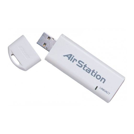
User Manual Wireless USB Keychain Adapter WLI-USB-KB11 www.buffalotech.com/wireless... - Page 2 Introduction 802.11b Wireless USB Keychain Adapter Windows XP – Installation & Configuration 1. Installing the Wireless USB Keychain Adapter Drivers: a. Insert the AirNavigator CD into the CD-ROM drive of the notebook. The Air Navigator Setup Wizard launches auto- matically. If the Air Navigator...
- Page 3 Review the Software License Agreement. Click the Yes but- ton to confirm your agreement with the terms and continue installing the Wireless USB Keychain Adapter drivers. Click the No button to abort the installation process.
- Page 4 Insert the Wireless USB Keychain Adapter, with the Buffalo logo facing up, into an available CardBus slot. CardBus slots are usually located on the left or right side of the notebook. Once the Wireless USB Keychain Adapter is installed correctly, the Found New Hardware Wizard will launch automatically.
- Page 5 Introduction c. Select the driver you want to install. If multiple drivers are listed, select the most recent driver version. Click the Next button. d. If a window opens, stating that your driver does not pass Windows Logo testing, click the Continue Anyway button.
- Page 6 SSID and click the Connect button to establish a connection. You may need to check the box indicating you are connecting to an unsecured network. See Step C if you need to enter an SSID network name or WEP/WPA encryption key.
- Page 7 Introduction c. Click the Advanced button to enter an SSID network name or WEP/WPA encryption key, if either is necessary. To add an SSID network name that is not available, click the Add button.
- Page 8 Introduction e. To configure a WEP/WPA encryption key, select the ap- propriate wireless network and click the Configure button. f. From the pull down menu, select the appropriate Net- work Authentication and Data Encryption for the wireless network. Enter and confirm the Network Key and Key Index.
-
Page 9: Installation & Setup
Insert the Wireless USB Keychain Adapter, with the Buffalo logo facing up, into an available CardBus slot. CardBus slots are usually located on the left or right side of the notebook. Once the Wireless USB Keychain Adapter is installed correctly, the Found New Hardware Wizard will launch automatically. - Page 10 Installation / Setup 2. Installing the Wireless USB Keychain Adapter-Drivers: a. Insert the AirNavigator CD. Click Next at the Welcome to the Found New Hardware Wizard. Select Search for a suitable driver for my device. Click the Next button to continue.
- Page 11 Installation / Setup c. Windows will display a driver you can use with the Wireless Desktop PCI Adapter. Click the Next button to continue. d. Windows 2000: If the Digital Signa- ture Not Found page opens, informing that no digital signature exists for the driver you are installing, click the Yes button to continue the installation process.
-
Page 12: Client Manager
Client Manager Client Manager Use Client Manager to configure your wireless network. Use Client Manager to survey and connect to available access points, enable and use WEP encryption, and create connection profiles. ■ Note: Client Manager does not function properly if the Windows XP Wireless Zero Configuration Service is enabled. - Page 13 Browse button and select another location. Click the Next button to continue to the Select Components page. 4. Select the components you want to install and click the Next button to continue to the Start Copying Files page.
- Page 14 Client Manager 5. Click the Next button to begin copying the necessary files to install Client Manager. 6.Click the Yes button, when prompted, to add a shortcut for Client Manager to your Windows Startup menu. If you click the Yes button, Client Manager will run at startup.
- Page 15 Use Client Manager to configure your wireless network. To assist in configuring your wireless network, Client Manager consists of the Status page, the Survey page, and the Profiles page. You can access each page by clicking the corresponding button on Client Manager. In addition to these pages, several dialog boxes are available to meet specialized configuration needs.
- Page 16 • Transfer Rate – Displays the data transfer rate, the rate at which you can transmit and receive data across the wireless network, in Mbps. The data transfer rate can be up to 54 Mbps. A variety of factors, including distance from the router, the allowable data transfer rates of other devices, and the physical conditions of the wireless environment, can affect the data transfer rate.
- Page 17 Client Manager Configuration • MAC Address – Displays the MAC address of your network device. A MAC address is a unique network name for each device on a network. 00:11:22:33:44:55 is an example of a valid MAC address. • Signal Strength – Displays the strength of the signal. Signal Strength is based on the peak signal level the wireless adapter receives from the wireless device to which it is connected.
- Page 18 If No is displayed in the WEP field and you click the Connect button, the wireless adapter will connect to the selected access point and the Status page will reopen. If Yes is displayed in the WEP field and you click the Connect button, the WEP Configuration dialog box will open.
- Page 19 The Profiles page allows you to add, delete, and edit your profiles, as well as import and export data.
- Page 20 Client Manager Configuration • Add – Click the Add button to open the New Profile dialog box and add a new profile. • Edit – Click the Edit button to open the Edit Profile dialog box and edit an existing profile.
- Page 21 • SSID – Enter the SSID of your network. The SSID is the unique network name that functions an identifier for your wireless devices. All wireless devices on a network must use identical SSIDs to successfully associate with other devices on the network.
- Page 22 Client Manager Configuration • Cancel – Click the Cancel button to return to the Profiles page without saving your specifications. • Signal Strength – Displays the strength of the signal. Signal Strength is based on the peak signal level the wireless adapter receives from the wireless device to which it is connected.
- Page 23 • SSID – Displays the current SSID of the profile you are editing. Enter any changes to your SSID in this field. The SSID is the unique network name that functions as an identifier for your wireless devices.
- Page 24 • WEP – Displays whether WEP encryption is currently used by the profile you are editing. Select Yes or No from the menu to change whether WEP encryption is used with the profile. Select Yes to enable WEP encryption. Select No to disable WEP encryption. If you select Yes from the WEP menu, the WEP Configuration dialog box will open when you click the Okay button.
- Page 25 New Profile dialog box or the Edit Profile dialog box. • Cancel – Click the Cancel button to return to the previous dialog box, either the New Profile dia- log box or the Edit Profile dialog box, without saving your specifications.
- Page 26 64-bit WEP encryption, WEP Type must be 64-bit encryption. • Key Format – Select the format for the WEP key, ASCII or Hex, from the menu. Select ASCII if you want to use alphanumeric characters. Select Hex if you want to use hexadecimal characters.
- Page 27 Cancel – Click the Cancel button to cancel your action. • Signal Strength – Displays the strength of the signal. Signal Strength is based on the peak signal level the wireless adapter receives from the wireless device to which it is connected.
-
Page 28: Wireless Zero Configuration
This service automatically polls the area for available wireless access points. If an available wireless access point is found, Windows attempts to connect to the access point. If no available wireless access points are found, you must manually add the access points. -
Page 29: Specifications
Access Mode Infrastructure mode, Ad-Hoc Security 128/64 Bit WEP Others Interface USB1.1 Power Consumption 1550mw Dimensions 1 1 x 25 x 83 mm ( 0.44 x 1 x 3.3 in ) Weight 20g ( 0.7oz ) Environmental Operation 0-55ºc, 20-80% (non-condensing) - Page 30 Outdoor 1 1Mbps 165 ft. (50m) 525 ft. (160m) 2Mbps 300 ft. (90m) 1310 ft. (400m) 1Mbps 375 ft. (1 15m) 1 750 ft. (550m) All distances are estimated. Wireless connections may be affected as physical conditions and circumstances vary.
-
Page 31: Troubleshooting (Faq)
What should I do if I already have a version of Client Manager on my notebook? Update your Client Manager to the version on the CD. If you do not update your Client Manager, there could be a loss of functionality, as some versions of Client Manager will not work properly with the G54 Wireless USB Keychain Adapter. - Page 32 Troubleshooting / FAQ Where can I attach my external antenna? Insert your external antenna into the antenna slot, located on the back of the G54 Wireless PCI Adapter. Why won't Client Manager function properly? Windows XP – The Wireless Zero Configuration Service conflicts with Client Manager. Select Start»Control Panel»Administrative Tools»Services to open the Services window.
- Page 33 UTP (Unshielded twisted munications between two devices. pair) cable and a star topology. 10 is 10 Mbps DCE (Data Communications Equipment): and 100 is 100 Mbps. Hardware used for communication with a Data 802.1x: The standard for wireless LAN authenti-...
- Page 34 Ethernet network that uses UTP (Unshielded DCE (Data Communications Equipment): twisted pair) cable and a star topology. 10 is 10 Hardware used for communication with a Data Mbps and 100 is 100 Mbps. Terminal Equipment (DTE) device.
- Page 35 Glossary to it, and retrieves the address when the device for Local Area Networks (LANs). It is a shared- becomes dormant for a period of time. media network architecture. The IEEE 802.3 standard details its functionality. DNS (Domain Name System): System used...
- Page 36 MDI/X (Media Dependent Interface/Cross-over): network in which the wireless network devices Port on a network hub or switch that crosses are made a part of the network through the Ac- the incoming transmit lines with the outgoing cess Point. receive lines.
- Page 37 Glossary NAT (Network Address Translation): An internet Plug and Play: Hardware that, once installed standard that enables a LAN to use one set of (“plugged in”), can immediately be used IP addresses for internal traffic and a second (“played”), as opposed to hardware that re- set for external traffic.
- Page 38 TCP/IP (Transmission Control Protocol/Internet Script: A macro or batch file containing instruc- Protocol: Protocol used by computers when tions and used by a computer to perform a task. communicating across the Internet or Intranet. Server: Any computer that makes files or...
- Page 39 UDP is used as an alternative to TCP/IP. VPN (Virtual Private Network): A security meth- Uplink: Link to the next level up in a communi- od to connect remote LAN users to a corporate cation hierarchy. LAN system.
-
Page 40: Fcc / Ce Information
• Reorient or relocate the receiving antenna. • Increase the separation between the equipment and receiver. • Connect the equipment into an outlet on a circuit different from that to which the receiver is con- nected. • Consult the dealer or an experienced radio/TV technician for help. -
Page 41: Important Note
Earth Station Equipment) As of April 8, 2000. Safety This equipment is designed with the utmost care for the safety of those who install and use it. However, special attention must be paid to the dangers of electric shock and static electricity when working with electrical equipment. - Page 42 FCC / CE Information EU Countries intended for use The ETSI version of this device is intended for home and office use in Austria, Belgium, Denmark, Finland, France (with Frequency channel restrictions), Germany, Greece, Iceland, Ireland, Italy, Luxembourg, Norway, The Netherlands, Portugal, Spain, Sweden, Switzerland and United Kingdom.
-
Page 43: Warranty Information
Buffalo Technology/(Melco Inc.) does not offer refunds for any product. © 2003 Buffalo Technology (Melco, Inc.) *11 Mbps is the IEEE 802.11g standard theoretical maximum data transfer rate. Actual wireless network throughput is limited by environmental and system factors and will be less. -
Page 44: Contact Information
GENERAL INQUIRIES Monday through Friday 8:30am-5:30pm CST Direct: 512-794-8533 Toll-free: 800-456-9799 Fax: 512-794-8520 Email: sales@buffalotech.com TECHNICAL SUPPORT North American Technical Support by phone is available 24 hours a day, 7 days a week. (USA and Canada). Toll-free: (866) 752-6210 Email: info@buffalotech.com... - Page 45 4030 W. Braker Ln. Suite 120 Austin, Texas 78759 Tel: 800-456-9799 Fax: 512-794-8606 Technical Support is available 24 hours a day, 7 days a week (USA / Canada) Toll-Free: 866-752-6210 email: info@buffalotech.com ©2004, Buffalo Technology (USA), Inc.